DIY Samsung Galaxy S23 Motherboard Replacement Guide
Duration: 45 minutes
Steps: 36 Steps
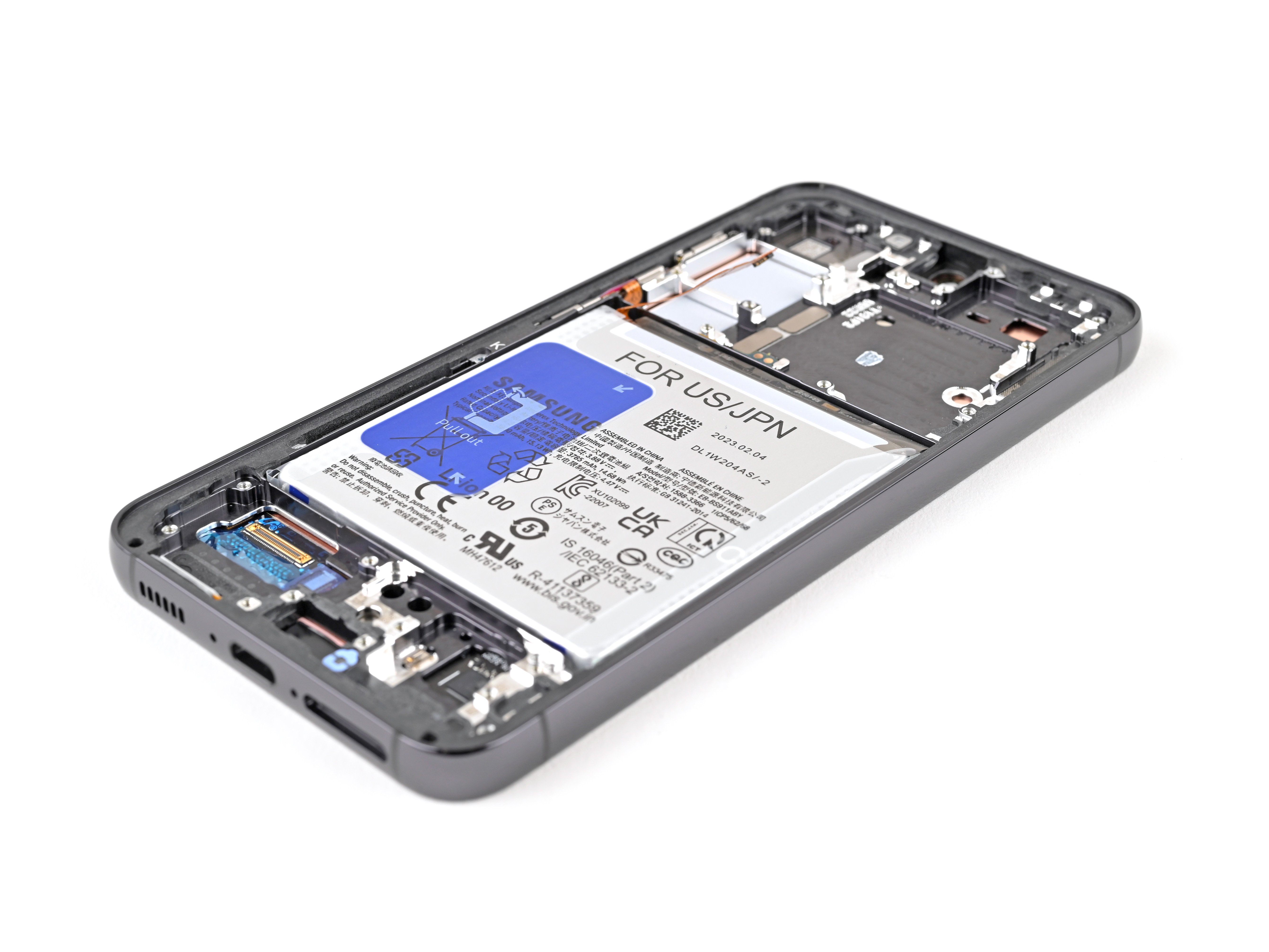
Get ready to swap out the motherboard in your Samsung Galaxy S23! Heads-up: Keeping that water resistance after the repair depends on how well you reapply the back cover adhesive. Just a reminder, your device will lose its IP (Ingress Protection) rating. If you need help, you can always schedule a repair.
Step 1


Before you start, make sure your phone’s battery is below 25% charged. A fully charged lithium-ion battery can be a safety hazard, so it’s better to be safe than sorry. If your battery is swollen, take the necessary precautions to avoid any accidents. If you need help, you can always schedule a repair
– Alright, first things first – let’s disconnect any cables from your phone. You know, those cords that keep it juiced up? Time to give them a break.
– Now, hold on tight to the side key and the volume down button. Give them a good squeeze and then select “Power off.” See? Turning off your phone is a piece of cake!
Step 2

If you need some extra heat, a hairdryer, heat gun, or hot plate can be your new best friend. Just don’t get carried away – we don’t want to turn your phone into a crispy treat! The display and battery are a little sensitive to heat, so be gentle. If you need help, you can always schedule a repair.
– Alright, time to get this party started! Let’s warm up that back cover with a hot iOpener. Hold it on the right edge for about two minutes. That’ll loosen up the glue holding it on. You got this!
Tools Used


Step 3


Having trouble getting that gap started? Try applying a bit more heat to loosen up the adhesive. Just be sure to follow the iOpener instructions so you don’t overdo it. If you need help, you can always schedule a repair
– First things first, grab a suction handle and stick it on the back cover, aiming close to the center of the right edge. You got this!
– Now, give that suction handle a confident pull with steady strength to create a little gap between the cover and the frame. Keep it smooth!
– Time to take action! Slide an opening pick into that gap you just made and let’s keep going.
Tools Used


Step 5

– Time to warm things up! Apply a heated iOpener to the bottom edge of the back cover for two minutes. This will help loosen the adhesive holding the cover in place. If you need help, you can always schedule a repair.
Tools Used
Step 6


– Let’s get that bottom right corner loose! Insert your opening pick and give it a little wiggle.
– Now, swing that pick around the corner, like you’re giving it a high five. This will help separate the adhesive holding things together.
Step 7


– Gently glide your trusty opening pick to the bottom left corner to break that adhesive seal.
– Keep the pick snugly in the bottom left corner to stop the adhesive from sealing up again.
Step 8

– Let’s heat things up! Apply a heated iOpener to the left edge of the back cover for two minutes. If you need help, you can always schedule a repair
Tools Used
Step 9


– Alright, let’s get that phone open! Grab your opening pick and slide it around the bottom left corner. You’ll feel the adhesive loosen up – like a little dance party for your phone’s case!
Step 10


– Let’s pop that back cover off! Insert a third opening pick at the bottom left corner.
– Now, slide your pick towards the top left corner to loosen that adhesive. Smooth sailing, right?
– Hold that pick in the top left corner to make sure the adhesive doesn’t stick back together. We’re almost there!
Step 11

– Let’s get started by heating up an iOpener and applying it to the top edge of the back cover for about two minutes. This will help loosen things up and make the repair process smoother. If you need help, you can always schedule a repair
Tools Used
Step 12


– Let’s get that top left corner open! Insert a fourth opening pick there, and then give it a little spin to loosen up the adhesive. You got this!
Step 13


– Let’s get this show on the road! Slide your trusty opening pick up to the top right corner to loosen the adhesive.
– Keep that pick in place up there, like a party favor. We don’t want that adhesive sticking back together, do we?
Step 14


Hey, don’t get too close to those rear cameras with your pick! Give those lenses some space – they’re delicate, and we don’t want to damage them. If you need help, you can always schedule a repair.
Hey there! Looks like we’ve got a little bit of adhesive hanging around under the flash.
You should see the opening pick peeking through the flash cutout. Keep going, you’re doing great!
– Let’s get this party started! Line up the tip of your trusty opening pick with the flash cutout. We’re going to give this phone a little wiggle room.
– Slide the opening pick under the top of the back cover, and you’ll feel it catch. You’ve got this, it’s like a dance! Keep sliding that pick toward the bottom. You’ll feel that adhesive let go.
– Keep sliding the pick down, and soon that back cover will be ready to party. If you’re having trouble, remember you can always schedule a repair. We’ve got your back!
Step 15


If your cover is still clinging to the frame like it’s afraid of letting go, gently slide an opening pick around the edges until the cover finally decides to part ways.
Now’s a great time to power on your phone and check all its functions before sealing everything back up. Just remember to turn it off completely before diving back into the repair!
– Grab and remove the back cover, but don’t worry if it’s a little tricky, you’re in good company!
– During reassembly, remove any adhesive chunks with a pair of tweezers or your fingers. If you’re having trouble, apply some heat and isopropyl alcohol (90% or greater) for a smooth removal.
– Looking for some custom adhesive solutions? No worries, check out our helpful guides schedule a repair for some tips!
– If you’re using double-sided tape instead, we’ve got your back with more handy guides schedule a repair.
Tools Used


Step 16


– Grab your trusty spudger and gently use its tip to lift and disconnect the wireless charging coil press connector from the motherboard. Easy peasy!
– When it’s time to reconnect those press connectors, just line them up like a pro and press down on one side until you hear that satisfying click. Then, do the same on the other side. Just a friendly reminder: avoid pressing down in the middle. If you happen to misalign it, the pins might bend and that’s a one-way ticket to permanent damage city!
Tools Used

Step 17


– Grab your trusty Phillips screwdriver and get ready to tackle those thirteen 3.5 mm-long screws that hold the wireless charging coil and the loudspeaker in place:
– Start by unscrewing the six screws that secure the wireless charging coil.
– Next up, take on the seven screws that are keeping the loudspeaker snug.


Step 19


– Give that loudspeaker a gentle nudge with your fingers to free it from the frame.
– Pop off the wireless charging coil and loudspeaker from the frame.
– When putting it back together, press around the edges of the loudspeaker to snap it back in place.
Step 20


– Now it’s time to carefully disconnect the battery press connector – use the point of your trusty spudger to gently pry it up and release it. If you need help, you can always schedule a repair
Tools Used
Step 21


– Now, take your trusty spudger and give that earpiece speaker press connector a gentle nudge to disconnect it. You’ve got this!
Tools Used
Step 22


– Grab your trusty Phillips screwdriver and get ready to unscrew those five 3.5 mm long screws that are holding the earpiece speaker in place. You’ve got this!
Step 23


Hey, be careful where you put that spudger! You don’t want to accidentally bump any delicate parts, right? Just stick to the plan and you’ll be good to go. If you need help, you can always schedule a repair
– Let’s get this earpiece speaker out! Slide the flat end of your spudger between the bottom of the speaker and the sliver shield on the motherboard.
– Now, give that spudger a little twist to unclip the speaker from the frame. Then, gently remove it.
– When you put it back together, remember to slide the top end of the earpiece speaker into the frame first. Then, press down and clip it back in. You’ve got this!
Tools Used
Step 24


– Now it’s time to get those cables disconnected. Use your trusty spudger to carefully pry up and release the primary and secondary interconnect cable press connectors from the daughterboard. If you need help, you can always schedule a repair
Tools Used
Step 25


– Go ahead and give the primary and secondary interconnect cable connectors on the motherboard some love – just like you did with the last step!
Step 26


– Unplug those interconnect cables like a pro!
Step 27

Handle with care! Those delicate surface-mounted components around this connector are just waiting to pop off if you pry at the wrong edges. Take it easy and make sure you’re working in a safe zone.
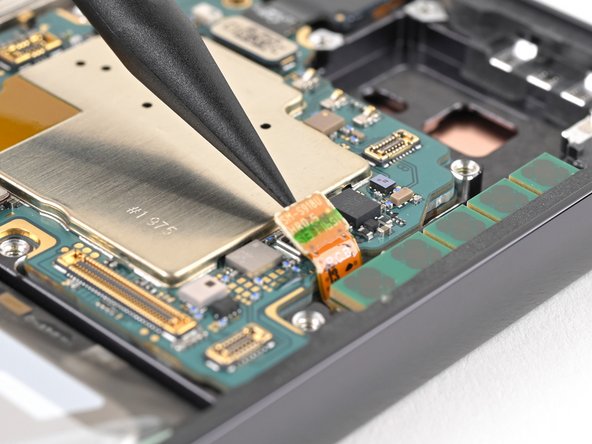
– Time to give that antenna connector a little nudge! Carefully slip the tip of your spudger between the left edge of the antenna connector and the sliver shield on the motherboard.
– Now, gently pry up the antenna connector to disconnect it. If you’re having trouble, don’t worry! You can always schedule a repair with us!
Tools Used
Step 28

– Alright, time to get those cables unhooked! Grab your spudger and gently pry up the display and 5G mmWave cable press connectors from the motherboard. You got this!
Tools Used
Step 29


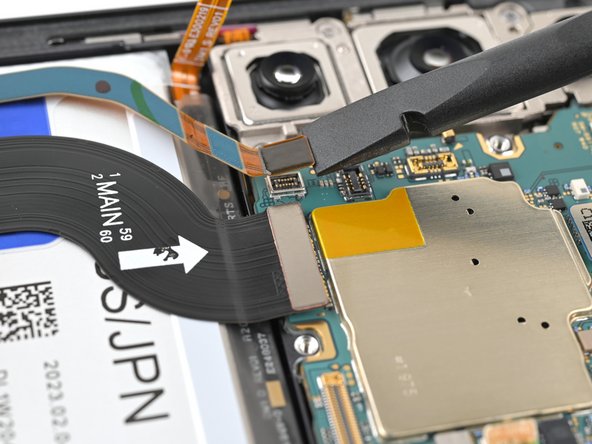
– Grab your trusty spudger and gently pry up the front camera press connector. It’s like giving the camera a little high five to say goodbye!
Tools Used
Step 30


– Alright, time to unleash your inner tech wizard! Grab your trusty Phillips screwdriver and give those two 3.5 mm screws holding down the motherboard a little love tap. They’ll be outta there in a jiffy! If you need help, you can always schedule a repair.
Step 31


– Let’s get that motherboard out! Slide the flat end of your spudger between the top edge of the motherboard and the frame, right near the earpiece speaker cutout.
– Time to twist and lift! Twist the spudger to give the motherboard a little lift, and then you can gently pull it out of the frame until you can get a good grip.
– Now you can remove the motherboard, nice and easy!
– Remember, when you’re putting everything back together, make sure all those cables are out of the way before you pop that motherboard back into its home. You don’t want to get those wires in a tangle! If you need help, you can always schedule a repair.
Tools Used
Step 32


Time to tackle those cameras! They’re nestled together like puzzle pieces, so start at the top and gently pull them out one by one. You’ve got this! If you need help, you can always schedule a repair.
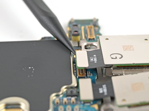
– Flip that motherboard over and get ready to meet the rear camera press connectors! They’re just waiting for a little nudge.
– Grab your spudger (that trusty tool!) and gently pry up the ultrawide camera press connector. It’s like a little dance, just a little push and pull, and you’ll be disconnecting in no time.
Tools Used
Step 33


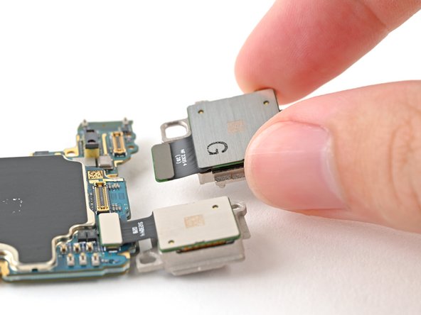
– Let’s free that ultrawide camera! It’s held in place by metal pegs connecting it to the motherboard and main camera.
– Keeping a firm grip on the motherboard, carefully lift the ultrawide camera up and out of its peg holes. You’ve got this!
Step 34

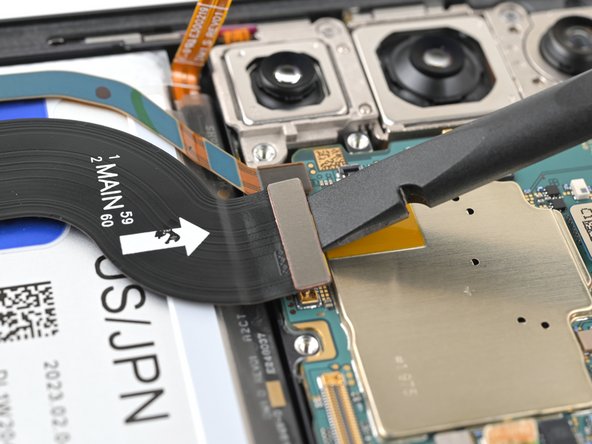
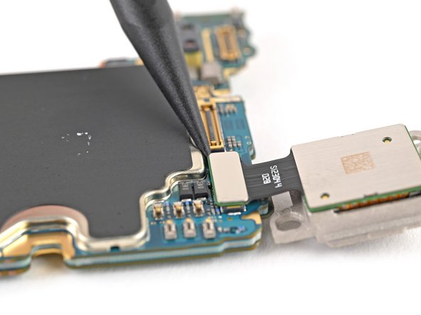
– Time to get started – use the point of a spudger to carefully pry up and disconnect the main camera press connector. Take your time, it’s easier than you think!
– Now, gently lift the main camera off the motherboard and remove it. You’re making great progress! If you need help, you can always schedule a repair
Tools Used
Step 35


– Let’s get that telephoto camera out! Use the pointy end of your trusty spudger to gently pry up the connector. It’s like you’re giving it a little high five.
– Now, lift the camera off the motherboard like you’re giving it a friendly wave goodbye. It’s ready to be replaced!
– When you’re putting things back together, make sure you pop the cameras back in the right order (Telephoto → Main → Ultrawide). You’ve got this! If you need help, you can always schedule a repair.
Tools Used