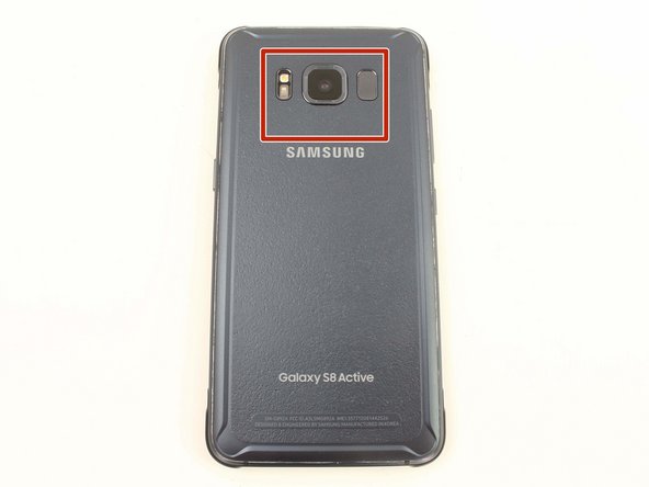
DIY Samsung Galaxy S8 Active Motherboard Replacement Guide
Duration: 45 minutes
Steps: 19 Steps
Hey there! Looks like we’ve got a little hiccup here. No worries, we’ll tackle this together step by step. If you need help, you can always schedule a repair to get things back on track. Let’s get started!
Get ready to embark on an exciting adventure as you replace or remove the motherboard in your Samsung Galaxy S8 Active with this fun-filled guide! Don’t forget to apply some fresh replacement adhesive to make your back cover stick like never before. Oh, and remember to charge your device below 25% before starting your journey to avoid any fiery explosions. If you need help, you can always schedule a repair!
Step 1


– Pop in the SIM card ejector tool (or an unfolded paperclip) into the tiny hole on the left side of the phone’s top edge.
– Gently press to pop out the SIM tray.
– Take out the SIM card tray from the device.
– To put the SIM card tray back, align the SIM card with the gold contacts facing up and the notch on the bottom right. Slide the SIM card back in by gently pressing it into the tray slot.
Step 2


Popping off the back cover of the S8 Active? Heads up, this will mess with its waterproof mojo. Make sure you have some fresh adhesive ready to go before you start, or keep your phone away from any liquid after you put it back together if you skip replacing the adhesive. If you need help, you can always schedule a repair
– First things first, let’s tackle those four sneaky black 3mm screws hanging out on the edges of your device. Grab your trusty TR6 Torx Security Screwdriver and give them a twist to set the rubber bumpers free!
– Now, gently peel off those rubber bumpers from the top and bottom edges of your device. They’ve done their job, and it’s time for them to take a break!
Tools Used

Step 3

Hey there! When using a heat gun, hair dryer, or hot plate, just remember the metal frame can get pretty toasty, so treat it gently.
Make sure not to go overboard with the heat – too much can harm the OLED display, battery, and other insides. Just give it about a minute to loosen up the stickiness.
To warm up those edges, you can go for an iFixit iOpener, a trusty hair dryer, or even a hot plate. Whatever gets the job done!
– Get a heat gun and gently warm up the edges of the back to make the adhesive holding the back cover to the frame nice and relaxed.
Tools Used

Step 4


– Get ready to be a phone repair magician! First, slide in the trusty Jimmy tool under the back cover’s edge.
– Once the Jimmy tool is snug under the cover’s edge, glamorously insert an opening pick into the seam to keep things together in case the Jimmy tool gets a little too jazzy or decides to take a break.
– Now, it’s time for the delicate dance around the top section of your device. Take it slow, show those cables some love – especially the ones for the fingerprint sensor and camera. And remember, no prying too hard at the top to protect that precious fingerprint sensor!
– Let’s groove to the next step – slide that fabulous Jimmy tool down the device’s sides, gently separating the adhesive like a pro.
Tools Used

Step 5

The fingerprint sensor cable hooks up at the top of your phone near the front-facing camera. Be a champ and ease off the back cover gently to avoid any cable drama. If you need help, you can always schedule a repair.
– Grab the opening pick and glide it smoothly through any remaining adhesive.
– Gently open the back cover so you can catch a glimpse of the fingerprint sensor flex cable connector.
Step 6


– Gently and carefully flip the cover over, placing it on top of the rest of the device.
– Using the flat end of a spudger, delicately disconnect the fingerprint flex cable.
– Take off the back cover with ease.
– When putting things back together, remember to align the fingerprint sensor cable by tilting the back cover. With a gentle touch, secure the cable in place over its socket using the flat end of a spudger.
Tools Used

Step 7


– Grab your trusty Phillips #00 screwdriver and pop out eleven 3.5 mm screws.
– Now, whip out that Phillips #00 screwdriver again and unscrew those two 2mm screws.
Tools Used

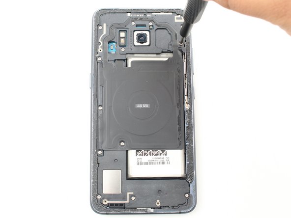
Step 8


– To begin, gently remove the NFC antenna and charging coil assembly using the trusty flat end of a spudger.
Tools Used

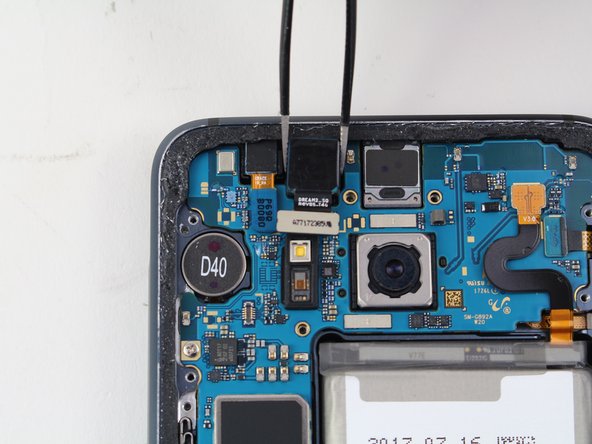
Step 10


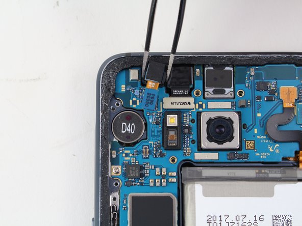
– Using the flat end of a spudger, carefully disconnect the iris scanner flex cable from the motherboard.
– With a gentle touch, grab your tweezers and lift the iris scanner out of its cozy little slot.

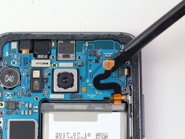
Step 11


– Pop off the front-facing camera flex cable from the motherboard using the flat end of your trusty spudger.
– Grab your tweezers and gently lift that camera out of its snug little slot.
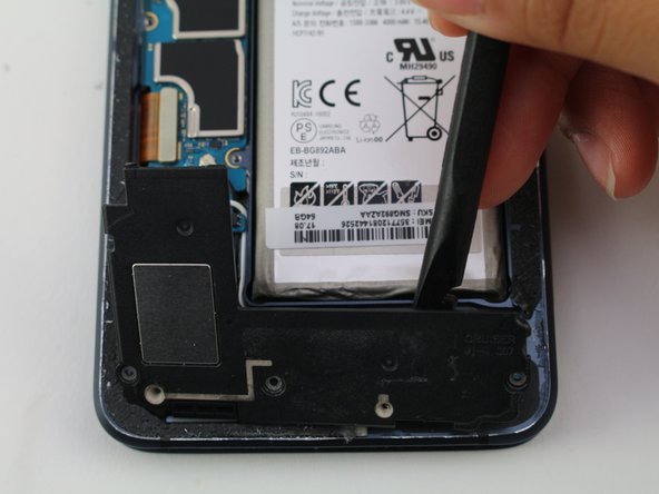
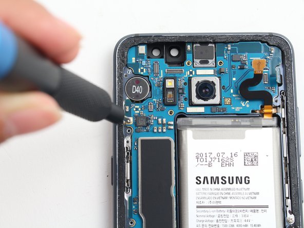
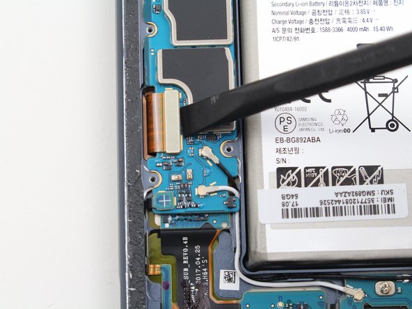
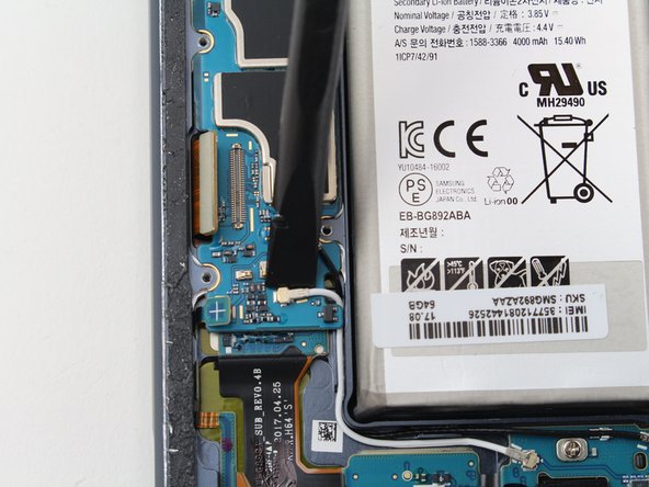
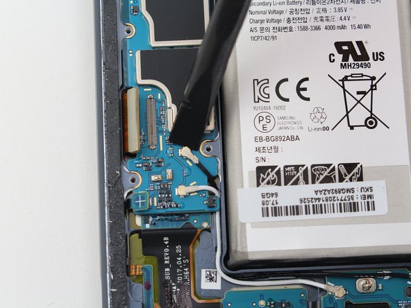
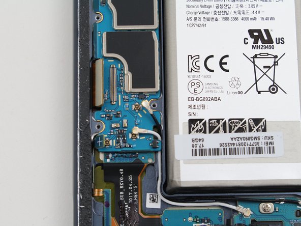
Step 12


– To kick things off, gently disconnect the battery flex cable using the flat end of a spudger.
Tools Used
Step 13

– Grab your trusty Phillips #00 screwdriver and unscrew that one 3.5 mm screw. You’re doing great!
Tools Used
Step 14


– Gently unhook the Volume Up, Volume Down, and Bixby button flex cable with the flat end of a spudger. If you need help, you can always schedule a repair
Tools Used
Step 15

– Gently detach the display flex cable using the flat edge of a spudger. You’re doing great!
Tools Used
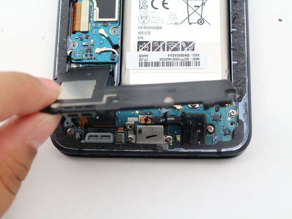
Step 16


– Easily detach the charging port flex cable with the handy flat end of a spudger.
Tools Used

Step 18

– Time to give those cables a break! The motherboard likes to chill on top of the daughterboard, with a flex cable connecting them. Say ‘see ya later’ to that cable bringing them together by gently using the flat end of a spudger. Let’s keep the party going!
Tools Used
Step 19


– Gently slide the flat end of your spudger along the top edge of the motherboard. You’ve got this!
– Carefully lift and remove the motherboard. It’s like a little surprise party, but for your device!
Tools Used