DIY Xbox One Kinect Colour Camera Replacement Guide
Duration: 45 minutes
Steps: 10 Steps
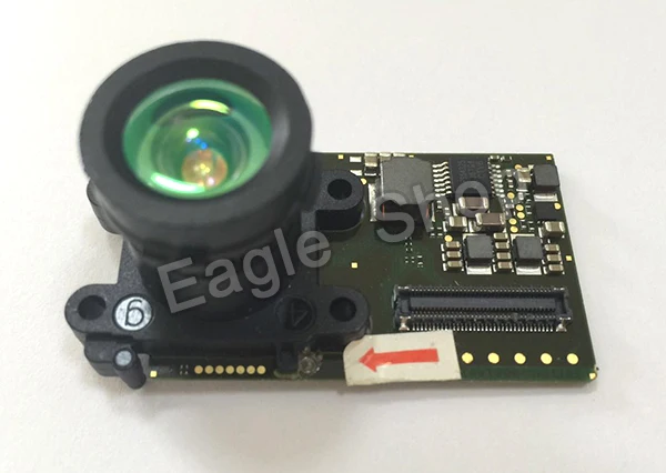
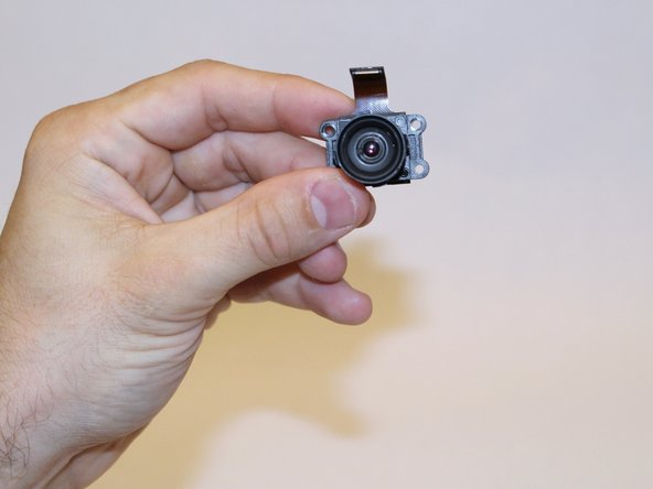
The color camera captures visual data and is securely mounted on the heat sink inside the Kinect.
Step 1

– Peel off that sticker on the bottom of your device like it’s a cozy little blanket.
– Next up, grab your trusty T10 screwdriver and unscrew the four 3.1×23.5 mm screws hidden under that sticker.
– While you’re at it, don’t forget to take out the four 3.1×7.5 mm screws lurking beneath the sticker as well. Remember, sizes and locations are crucial, so keep those in mind!
Step 2


– First things first, let’s get that back panel off so we can dive in! Just gently pry it away.
– Next up, it’s time to tackle those black panels flanking the Kinect. Remove them, and give a nod to the 3.1×7.5mm T10 screws hiding beneath. You’ve got this!
Step 3


– Let’s get this party started! Give those outer case sides a firm thumbs-up. It’s like a high five for the internal assembly – it’ll pop right out.
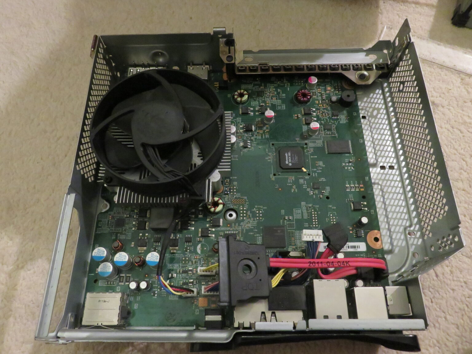
– Now, grab your trusty spudger and gently lift that internal assembly. Think of it as giving it a little nudge to get going.
– And there you have it! You’ve successfully separated the case and now you can check out the inner workings – heat sink, microphone, and LED sensor, oh my!
Tools Used

Step 4

– Time to get to work! First, take out those eight 2.9×7.6 mm T9 screws sitting cozy at the back of the internal case.
– Now, gently lift the internal metal case away from the plastic shell that’s giving the heat sink assembly a nice hug. You’re doing great!
Step 5


– Let’s give that ribbon cable between the sensor driver board and the motherboard a little break – disconnect it!
– Next up, give that 3.0×7.5 mm T9 screw holding the sensor driver board to the heat sink a little twist to the left – and out it comes!
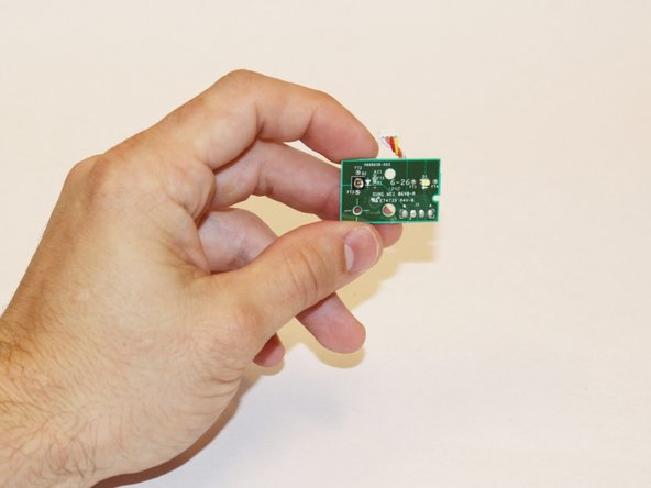
– Alright, that infrared sensor board for the Kinect is ready to come out – let’s give it a gentle lift.
Step 6


– Gently wiggle out the ribbon cable that connects to the microphone using your trusty tweezers.
– Unscrew those four 3.1×7.7 mm T9 screws that are holding the microphone snugly against the heat sink assembly.
– Time to say goodbye to the stand—just remove it!
Step 7
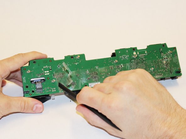

– Let’s kick things off by unscrewing those eight 3.0×7.6 mm T9 screws from the motherboard. You’ve got this!
– Now, gently peel away the plastic film from the motherboard using your trusty spudger. Take your time, it’s like unwrapping a present!
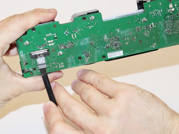
– Next up, carefully detach the ribbon cable that connects to the color camera with the spudger. You’re making great progress!
Tools Used
Step 8


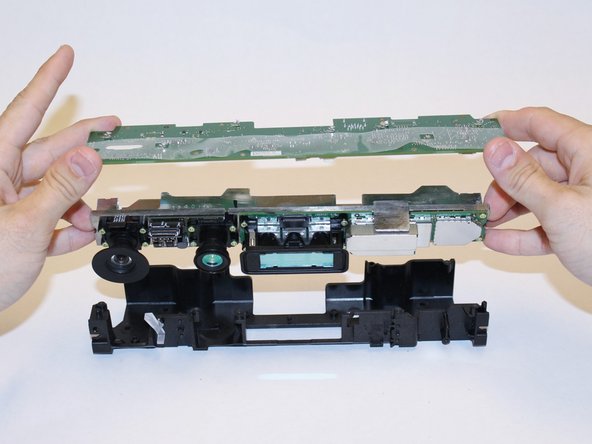
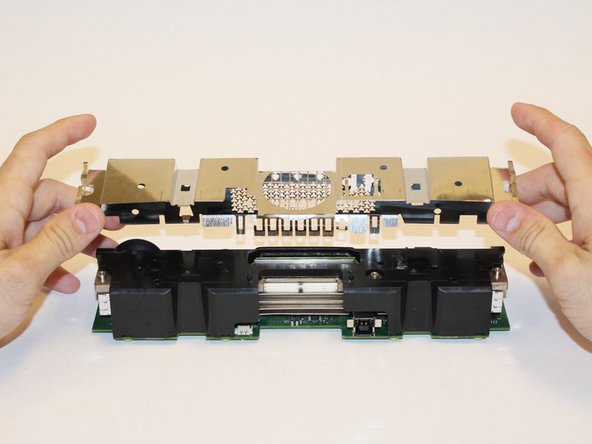
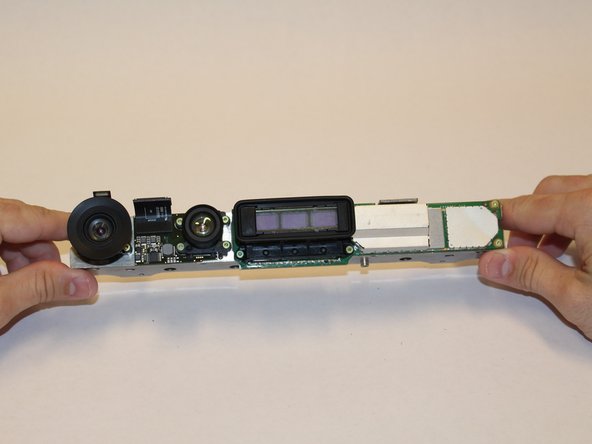
– Alright, let’s give this motherboard a little lift! Gently remove the motherboard and heat sink assembly from the plastic shell. Once you’ve done that, you’ll be able to get to the components attached to the heat sink.
Step 9
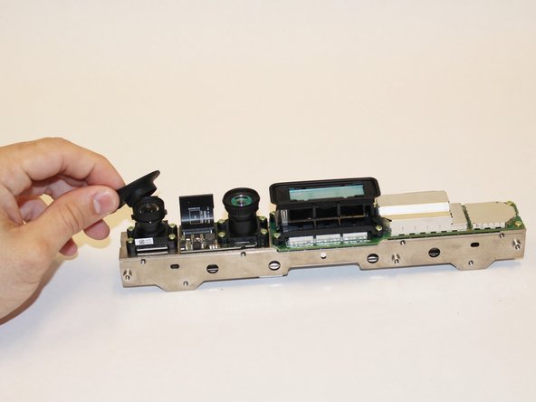

– Alright, let’s get this party started! First things first, take off the Colour Camera’s lens cap. You know, just to make things a little less crowded in there.
Step 10

– Now it’s time to put everything back together! Just retrace your steps and follow these instructions in reverse. You’ve got this!
– If you hit a snag and need a hand, feel free to schedule a repair.
–
Tools Used
Success!