Fairphone 1 Display Assembly Replacement
Duration: 45 minutes
Steps: 28 Steps
Get ready to breathe new life into your Fairphone by replacing the display assembly, complete with a brand new LCD screen, front glass, and digitizer. Follow this step-by-step guide to learn how to do it yourself. If you need help along the way, don’t worry, you can always schedule a repair.
Step 1


Notice a small dent on the side of your phone, near the bottom of the back cover? Don’t worry, we’ve got you covered!
– With that little gap you just made, use your fingernail to gently pop off the bottom part of the back cover.
Step 2


– Gently slide the back cover down and carefully take it off the phone. Easy does it!
Step 3


There’s a tiny dent right below the battery on the back of the phone. Nothing to worry about, just a little bump!
– Gently slide your fingernail into the little gap and give the battery a nudge toward the top of the phone.
– Now, carefully pull the battery out, away from the phone. You’re almost there!
Step 4

– Pop that battery out of your Fairphone and set it aside—let’s give your phone a fresh start!
Step 5


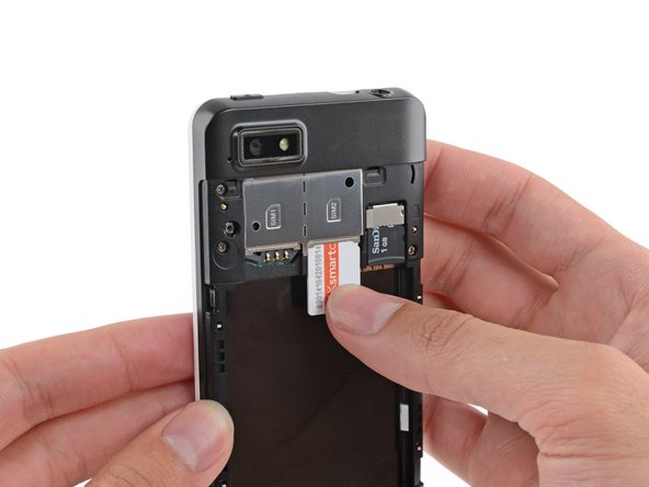
Take out all SIM cards before you dive in—your phone will thank you later!
If you’ve got a second SIM card, go ahead and give this step another spin.
– Gently slide the SIM card straight down and out of its tray using your finger – easy does it!
– Now, carefully remove the SIM card from your Fairphone. You’re making great progress!
Step 6

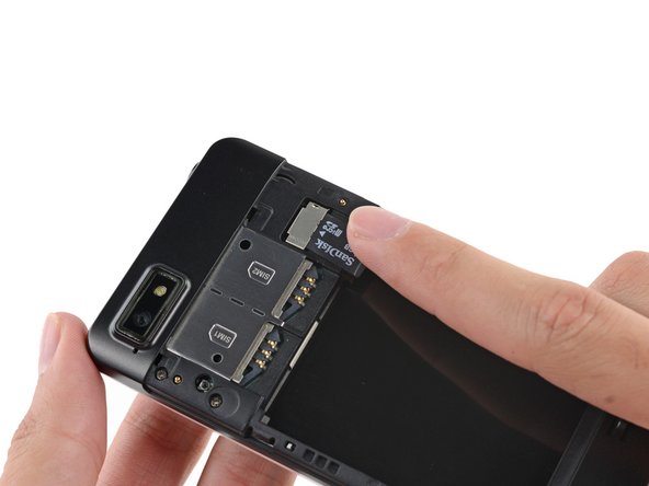
– Got a microSD card? Gently slide it out of its slot using your finger. Nice and easy!
– Pop out the microSD card from your phone. It’s as simple as that!
Step 7

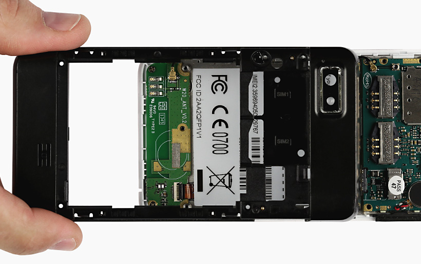
– Take out the five 3.9 mm Phillips #000 screws that are holding the midframe and display assembly together.
Step 8


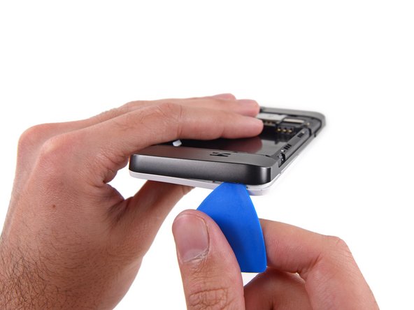
The midframe is held in place by a bunch of tiny plastic clips that snap onto the display assembly.
– Grab an opening pick and gently work your way around the midframe, carefully separating it from the display assembly. Take your time, no rush!
– Start right below the volume rocker and slowly move down towards the bottom, making sure to release the plastic clips along the way. Keep it steady, you’re doing great!
Step 9

– Gently work your way around the corner to separate the midframe from the display assembly without rushing it.
Step 10

Once you’ve made it around that last corner, the midframe should come loose from the bottom and sides.
Step 11


Keep those opening picks safe! Avoid prying close to the power switch, USB port, or headphone jack to prevent bending or damage.
– Slide the opening pick gently along the top seam to get things started.
Step 12

– Now it’s time to get a little more aggressive – carefully separate any remaining clips and gently pry the midframe away from the phone. You’re making great progress!
Step 13


When putting everything back together, make sure those buttons are facing the right direction. The rubber backings need to snugly fit into their designated channels in the assembly, so take your time and get it just right.
– Grab your tweezers and gently lift out the volume rocker and power buttons from the display assembly.
Tools Used

Step 14

Be careful not to pull the whole socket off the board – just disconnect the connector from its socket. It’s like a gentle tug, not a yank!
– Grab your trusty spudger and use the flat end to gently disconnect the antenna cable connector. Easy does it – you’ve got this!
Tools Used

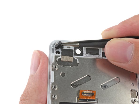
Step 15

– Time to get a little handy! Use tweezers to carefully remove the adhesive foam tape from the top of the digitizer cable ZIF socket. Take your time and be gentle, we’ve got this!
Tools Used


Step 17

– Unscrew the three 2.5 mm Phillips #000 screws holding the motherboard to the display. Keep those tiny screws somewhere safe—they love to disappear!
Step 18


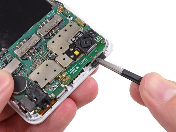
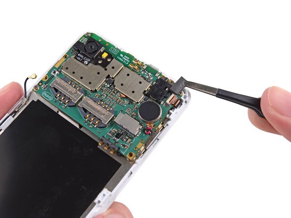
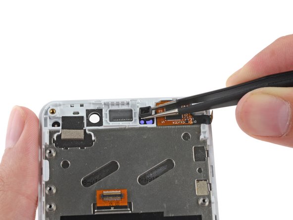
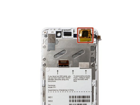
Hold up—don’t yank out the motherboard just yet! It’s still hanging on by the display data cable.
The rear-facing camera might be stuck to the display assembly, so try carefully prying it and the motherboard up together – it’s a delicate step, but you’ve got this!
– Carefully lift the top part of the motherboard just enough to reveal the display data cable underneath. A gentle nudge is all it takes!
Step 19

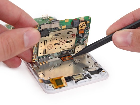
– Grab a spudger and gently use the tip to disconnect the display data cable from the back of the motherboard. It’s like giving it a little break—just a tiny nudge and you’re good to go!
Tools Used
Step 20

– Gently detach the motherboard from the display assembly. Take your time here, making sure everything is loose and ready to come apart.
Step 21

Be gentle when prying the connector—focus on the connector itself, not the socket!
– Gently pry up the antenna cable connector using the flat end of your spudger to disconnect it.
Tools Used
Step 22


– Grab your spudger and gently pop open the little tab on the daughterboard data cable’s ZIF connector. It’s easier than finding matching socks.
– Now, take your tweezers and carefully slide the daughterboard data cable out of its socket. Nice and easy—no tug-of-war needed!
Step 23

– Let’s give the Wi-Fi daughterboard a break and take out the screws holding it to the display assembly:
– Pop out the two 2.5 mm Phillips #000 screws.
– Don’t forget that sneaky 1.6 mm Phillips #000 screw hiding in there too.
Step 24


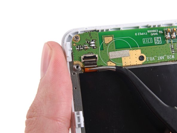
The Wi-Fi antenna daughterboard is gently stuck to the front assembly with light adhesive—nothing too clingy, but you’ll want to lift it with care.
– Gently use tweezers to lift the board and carefully remove it from the phone.
Tools Used
Step 25
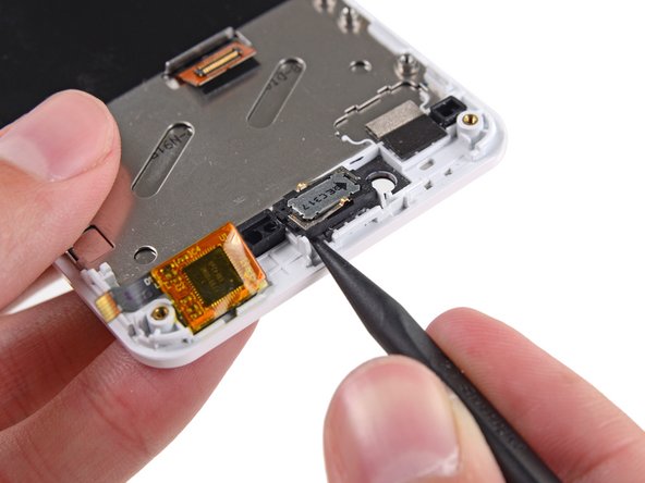

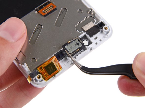
The earpiece speaker is gently secured to the back of the display assembly with a bit of adhesive. A little wiggle and it should come off without a fuss.
– Grab the tip of your spudger and gently work your way around the speaker to lift it off the display assembly.
– Once it’s loose, carefully remove the speaker.
Tools Used
Step 26


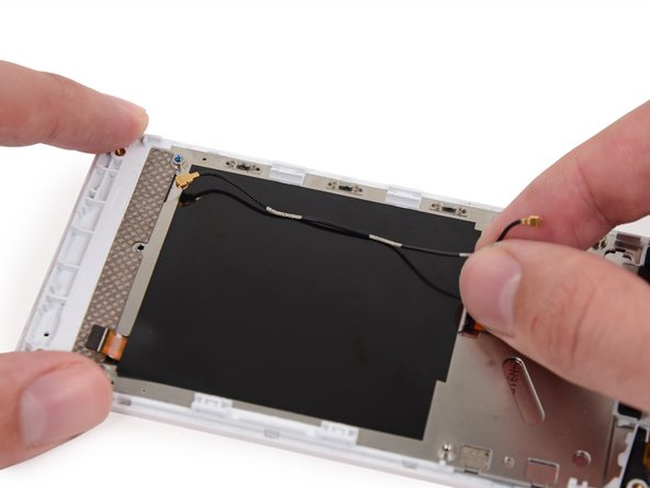
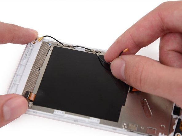
– Gently unplug the antenna interconnect cable from the display assembly. Take your time—no rush!
– Notice the three shiny sections of this cable? They slide right into the grounding clips along the side of the display. Give them a look so you remember how they fit when you put things back together.
Step 27

– First, carefully remove the rubber guide from the recess near the front-facing camera hole. Don’t worry, this little guy is easy to handle.
– Now, be sure to hang onto that rubber stopper – you’ll want to transfer it to your new display. Think of it as giving your device a fresh new face, with all the original parts intact.
Step 28

– Put your device back together by simply reversing these steps—easy as that!
– If you get stuck or want a pro to handle it, you can always schedule a repair.
Success!