Fairphone 1 RF Cable Replacement
Duration: 45 minutes
Steps: 26 Steps
Get ready to breathe new life into your Fairphone by replacing the RF Cable. Follow this step-by-step guide to learn how to do it yourself. If you need help along the way, don’t worry, you can always schedule a repair.
Step 1


Check out the tiny notch on the side of your phone near the bottom of the back cover—it’s your ticket to popping it open!
– Use the indentation to your advantage and carefully pry the bottom part of the back cover away from the phone using your fingernail. If it doesn’t budge, don’t worry, it’s supposed to be a bit tricky – just be gentle and patient.
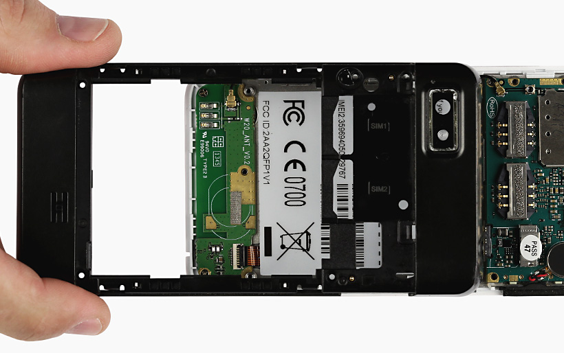
Step 2


– Gently slide the back cover down and carefully lift it off the phone.
Step 3


Look for a tiny dip on the back of the phone just beneath the battery.
– Slip your fingernail into the little groove and nudge the battery upward toward the top of the phone.
– Gently pull the battery away from the phone to free it.
Step 4

– Pop out the battery from your Fairphone—easy does it!
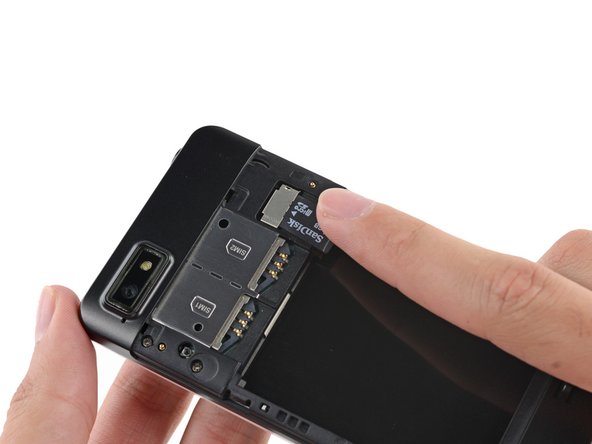
Step 5


Don’t forget to pop out all SIM cards before diving into your phone repair adventure!
Got a second SIM card? Just repeat the process and you’ll be good to go!
– Gently slide the SIM card straight out of its tray using your finger.
– Take the SIM card out of your Fairphone and set it aside.
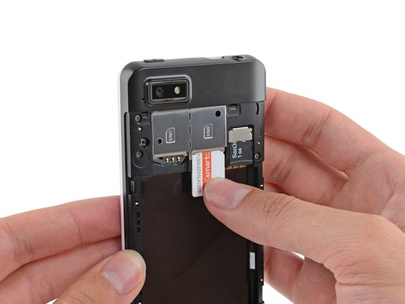
Step 6

– Got a microSD card chilling in your phone? Use your finger and slide it straight out of the slot—no tools needed.
– Now just take the microSD card out and set it aside for safekeeping.
Step 7

– Unscrew the five 3.9 mm Phillips #000 screws that hold the midframe to the display assembly—time to loosen things up!
Step 8


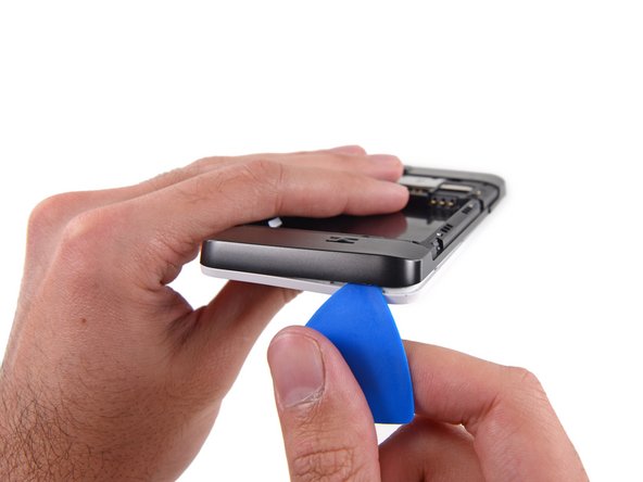
The midframe is held onto the display assembly with several tiny plastic clips.
– Grab your opening pick and gently wedge it between the midframe and display assembly.
– Kick things off just under the volume buttons and slide your way down to the bottom, popping those side clips free as you go.
Step 9

– Swing around the corner with care, loosening the midframe from the display assembly—smooth moves here keep everything happy.
Step 10

Once you’ve rounded the next corner, the midframe should pop free along the bottom and sides—looking good!
Step 11


Keep those opening picks safe and sound—avoid prying near the power switch, USB port, or headphone jack to prevent any bending or damage.
– Now it’s time to get this repair started! Run the opening pick along the top seam and gently pry it open.
Step 12

– Carefully detach any remaining clips and gently remove the midframe from the phone. It’s like giving your phone a little stretch – be patient and take it slow.
Step 13


When putting everything back together, double-check that your buttons are facing the right direction. Those rubber backings need to snugly fit into their designated channels in the assembly, so make sure they’re lined up properly.
– Grab your tweezers and gently pop out the volume rocker and power buttons from the display assembly. Easy does it!
Tools Used

Step 14

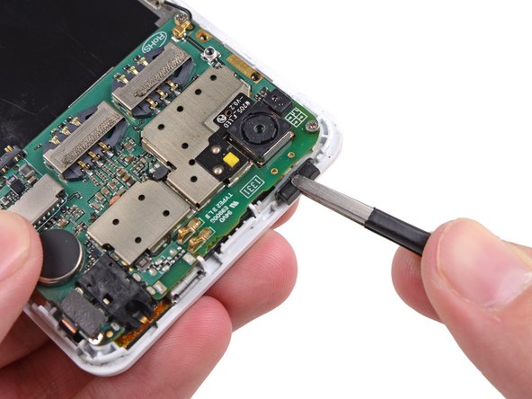
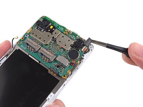
Be careful when disconnecting the connector – just pull it out of its socket, don’t try to remove the whole socket from the board!
– Gently use the flat end of a spudger to disconnect the antenna cable connector. Take your time, no rush!
Tools Used

Step 15

– Time to get up close and personal with that digitizer cable ZIF socket! Use your trusty tweezers to carefully remove the adhesive foam tape from the top – it’s like a little sticker, but be gentle so you don’t damage anything.
Tools Used


Step 17

– Take out the three 2.5 mm Phillips #000 screws holding the motherboard in place on the display assembly.
Step 18


Hold off on removing the motherboard just yet! It’s still hanging out with the display assembly, connected by that display data cable. Patience is key here!
The rear-facing camera might be stuck to the display assembly. Gently work on prying both the camera and motherboard together to free them.
– Carefully lift the top part of the motherboard just enough to reveal the display data cable underneath.
Step 19

– Grab your spudger and gently pop the display data cable off the back of the motherboard. Easy does it!
Tools Used
Step 20

– Gently lift out the motherboard from the display assembly—slow and steady wins the race!
Step 21

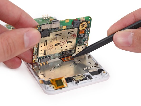
When you’re prying, make sure you’re lifting the connector itself, not the socket it’s attached to.
– Gently use the flat end of your spudger to unplug the antenna cable connector—smooth moves here!
Tools Used
Step 22


– Time to get started! Use the tip of a spudger to carefully flip open the tab on the daughterboard data cable ZIF connector – it’s like opening a little door.
– Next, use tweezers to gently pull the daughterboard data cable away from its socket. Take your time and be patient, you’ve got this!
Step 23

– Let’s get started by removing the screws that hold the Wi-Fi daughterboard in place:
– You’ll need to take out two 2.5 mm Phillips #000 screws
– And don’t forget the one 1.6 mm Phillips #000 screw
Step 24


The Wi-Fi antenna daughterboard is gently stuck to the front assembly with a light adhesive, so take your time peeling it off carefully.
– Time to get this board out! Use your trusty tweezers to carefully pry it up and remove it from your phone. Take your time, and it’ll be out in no time!
Tools Used
Step 25
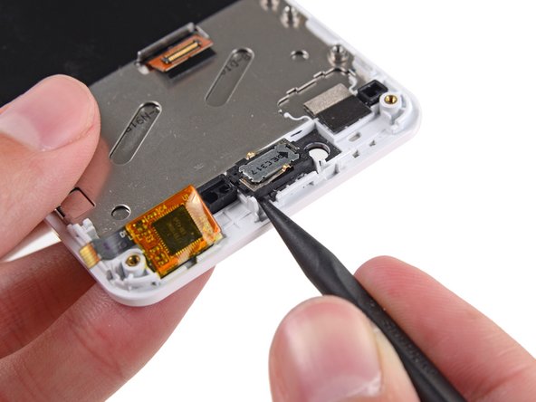

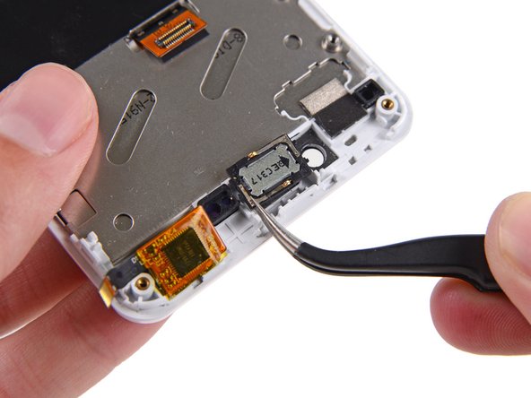
The earpiece speaker hangs out on the back of the display with just a bit of gentle adhesive keeping it company.
– Gently lift the speaker out of the display assembly using the tip of a spudger—take your time, no need to rush.
– Once it’s loose, go ahead and remove the speaker.
Tools Used
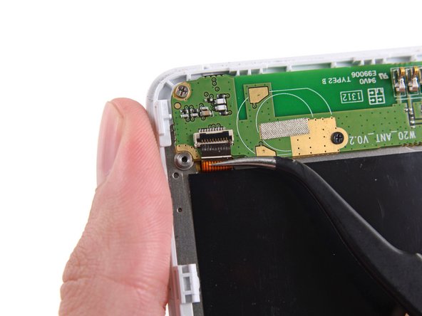
Step 26

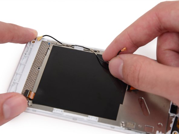
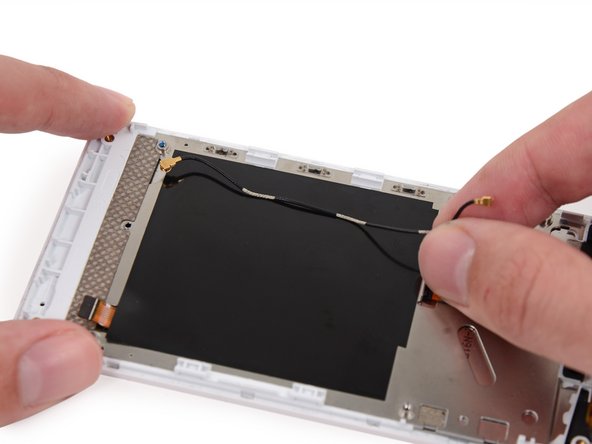
– Gently unplug the antenna interconnect cable from the display assembly.
– Notice the three cable sections with shiny metal bits? Those slide right into the grounding clips along the display assembly’s side. Easy does it!
Success!