Google Pixel 4a 5G Vibrator Motor Replacement
Duration: 45 minutes
Steps: 40 Steps
This repair guide is brought to you by the team at Salvation Repair. Please note, it’s not officially endorsed by anyone else. For more details about our repair guides, check them out here.
The Pixel 4a 5G’s display panel is delicate, so handle it with care. You wouldn’t want to accidentally crack it!
Ready to swap out the vibrator motor on your Pixel 4a 5G? This guide will walk you through it. Just a heads up: the display panel on the Pixel 4a 5G is on the delicate side, so be extra careful when handling it. If you’re reusing the screen, make sure to follow the opening procedure closely. If you need help, you can always schedule a repair.
Step 1


– Grab a SIM eject tool, a tiny screwdriver bit, or a straightened paper clip and gently poke it into the little hole on the SIM tray.
– Give it a firm but friendly press right into the hole to pop the SIM card tray out.
– Carefully pull out the SIM card tray and set it aside.
Step 2


It’s time to gently lift the screen off the phone. But before you dive in, take a moment to review the important notes below to ensure you’re ready for the next steps.
– Take a moment to check out the two seams along the edge of your phone:
– Before diving in, make sure you’re familiar with these areas on the screen:
– Screen seam: This is the line where the screen meets the rest of the phone. It’s your go-to spot for prying, so no worries—just be gentle.
– Frame seam: This is where the plastic frame connects with the back cover, held in place by screws. Whatever you do, don’t pry here.
– Screen flex cable: Don’t push the opening pick too deep—stay within the instructed depth to avoid damaging the cable.
– Adhesive perimeter: Be cautious here! Prying beyond this narrow zone or without the right angle could risk damaging the OLED panel.
Step 3
You can use a hair dryer, heat gun, or hot plate, just make sure not to overdo it! Too much heat can be a bummer for your phone’s display and internal battery, which don’t handle heat like a champ.
– Apply some heat to the right edge of the display with a heated iOpener for about one minute. This helps to soften the adhesive, making the next steps a whole lot easier.
Tools Used

Step 4


If your screen is shattered to smithereens, slap on a layer of clear packing tape to give that suction cup something to grip. No tape? No problem—strong tape can do the job just as well. And if you’re feeling adventurous, a dab of superglue can secure the suction cup right onto the cracked glass. Just be careful not to glue your fingers!
– Stick a suction cup near the right edge of the screen—get it as close as you can!
– Give the suction cup a firm, steady pull to pop things open.
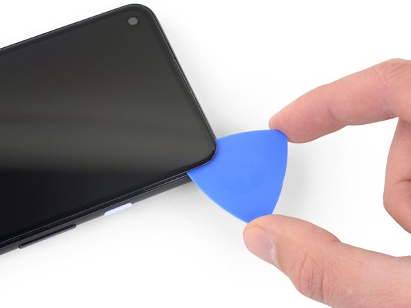
– Slip the tip of an opening pick into the screen gap, going no more than 1 mm deep.
Step 5


If you feel the pick bumping against something hard, stop! You’re probably pressing too close to the OLED panel’s edge. Try tilting the pick at a different angle and give it another shot.
This step shows you how to carefully slip in your pick without risking damage to the OLED panel. Make sure to do this before you start slicing through the adhesive.
– Time to get your pick in position! With the pick about 1 mm into the gap, gently tilt it upwards to get a nice steep angle going.
– Carefully push the pick into the gap, about a quarter inch or 6 mm in – that’s the sweet spot. It should slip right under the OLED panel, and you’re making progress!
Step 6


Keep that pick steady and don’t slide it in deeper than 1/4 inch (6 mm)—those flex cables are delicate and deserve your TLC!
– Gently slide the pick along the right edge of the screen to slice through the adhesive. Take it slow and steady!
– Once you reach the bottom-right corner, leave the pick in place to keep that adhesive from sealing back up. Nice job!
Step 7


Up at the top edge of the screen, there’s a mesh guarding the earpiece speaker—kind of like a tiny superhero cape for sound quality. If you don’t have a replacement, be extra careful not to lose or damage this little guy.
The screen adhesive isn’t exactly clinging for dear life, so no need to blast it with heat right away. But if slicing through it feels like an uphill battle, give the stubborn spots a one-minute warm-up session and try again.
– Slip another opening pick into the right edge of the phone where a gap has already started to form—this angle helps keep the OLED panel safe and sound.
– Carefully slide the pick along the top edge to slice through the adhesive.
– Keep that pick wedged in place along the top to stop the adhesive from snapping back together.
Step 8


If you’re having trouble slicing through the screen, give that tricky spot a quick blast of heat for about a minute and give it another go. It should make things a lot smoother!
– Slide an opening pick into the top edge of your phone where the gap is already grooving—easy does it, we want that OLED panel safe and sound!
– Work the pick around the top-left corner near the camera window—slice and dice (without the mess).
– Keep that pick snug along the left edge to hold your progress and stop the adhesive from making a comeback.
Step 9


Heads up! You’re working close to the screen flex cable and digitizer—handle with care! Precision is key, so take it slow and stay sharp.
If the screen is being stubborn to slice, warm up the tricky spot for about a minute and give it another go.
– Gently slide the opening pick along the left edge of your phone to slice through the adhesive like a pro.
Step 10


Heads up! You’re slicing really close to the screen’s flex cable and digitizer, so take your time and steady those hands.
If you’re having a tough time slicing through the screen, no worries! Just apply some heat to the stubborn spot for about a minute, then give it another shot. It should make things a lot smoother.
– Glide the opening pick smoothly around the bottom-left corner and across the base of the display, slicing through the remaining adhesive like a pro.
Step 11


Hold your horses on that screen removal!
– Now that you’ve made your way around the edge of the phone, gently lift up the right side of the screen—think of it like opening a book. Just a little peek, no rush!
– Grab your opening pick and carefully slice through any leftover adhesive. Take your time; it’ll all come apart smoothly.
Step 12


Handle that attached ribbon cable with care – we don’t want it feeling any pressure!
– Gently lift from the top edge and swing the screen over the bottom edge until it can rest glass-side down. Just like a graceful dance move, but for your tech!
Step 13


– Gently coax off the tape that’s keeping your screen connector snug using your trusty fingernail or a pair of tweezers. Take your time – this part’s important!
– If the tape looks good, feel free to use it again when putting everything back together. If it’s seen better days, just swap it out for some Kapton tape and you’re all set!
Tools Used

Step 14


Heads up! The plastic cover might suddenly pop up and take a little leap.
– Slide the spudger’s tip into the gap holding the screen flex cable’s plastic cover.
– Gently lift the plastic cover straight up until it pops free.
– Take off the plastic cover and set it aside.
Tools Used

Step 15


– Grab your spudger and gently use the tip to lift and disconnect the screen flex cable. Take your time, no rush!
– When it’s time to reconnect those press connectors, make sure you align them carefully. Start by pressing one side down until you hear that satisfying click, then do the same for the other side. Avoid pressing the middle. If things aren’t lining up just right, the pins can bend, and that could cause some serious damage. So, keep it steady!
Tools Used
Step 16


When your device boots up after putting everything back together, the screen will go through a quick calibration dance. Just let it do its thing—don’t tap the screen during this step! Interfering could mess up the touch calibration and cause some frustrating touch issues later on.
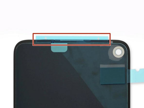
Check out the third photo to help you place those adhesives just right!
– Start by gently removing the screen.
– Ready to install your shiny new screen? Let’s do this!
– First things first—check if your replacement screen comes with the speaker mesh and the top edge adhesive already on it.
– If it does, awesome! You can skip the top edge adhesive part.
– If it doesn’t, peel off the larger clear liner from the top edge adhesive and stick it onto the screen (not on the frame). Just make sure that the larger cutout aligns perfectly with the speaker mesh.
Step 17

Keep an eye on every single screw during this repair—each one has a special spot it wants to return to, so don’t let them wander off!
– Grab your trusty T3 Torx driver and unscrew the nine 4.4mm screws holding the back cover to the midframe. Easy does it—keep them all in a safe spot, you’ll need them again soon!
Step 18


– Grab your trusty opening pick and gently slide it into the tiny gap between the midframe and the back cover, just above where the SIM card slot is hanging out.
– Now, make your way down the right edge of your phone with that pick, giving a little nudge to all those plastic clips holding the back cover in place. They’ll pop right off!
Step 19


– Keep gliding that opening pick along the top, left, and bottom edges of your phone until all those little plastic tabs holding the back cover to the midframe pop free. You’re doing great!
Step 20


Hold up! Don’t rush to remove the back cover just yet – it’s still connected by two ribbon cables. Take your time, and remember, patience is key.
– Flip your phone over so the back cover is facing up—give it a moment, it’s about to shine.
– Gently swing the back cover upward like you’re revealing a masterpiece. No rush, let it flow.
– Lean the cover against something sturdy—a cardboard box, soda can, or whatever’s nearby. Keep it chill, but secure.
Step 21


– Grab your trusty T3 Torx screwdriver and let’s dive in! Start by unscrewing the seven screws that are holding the motherboard bracket in place:
– You’ll need to tackle four screws that are 4.0 mm long.
– And don’t forget about the three screws that are 2.1 mm long.
Tools Used

Step 22


– Take off the motherboard bracket to get things moving.
Step 23


– Gently use the tip of your spudger to unplug the battery cable from the motherboard. Take your time, it’s a simple step, but crucial!
Tools Used
Step 24

– Gently use the spudger’s tip to lift and disconnect the fingerprint sensor cable. Take it slow and steady—no rush here!
Tools Used
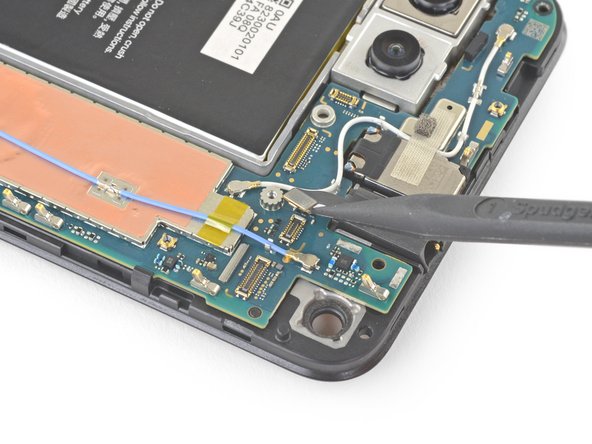
Step 25

– Take the spudger and gently nudge it under the front sensor array cable to pop it up and disconnect it. Easy peasy!
Tools Used
Step 26


– Pop off the back cover—yep, it’s time to get under the hood!
Step 27


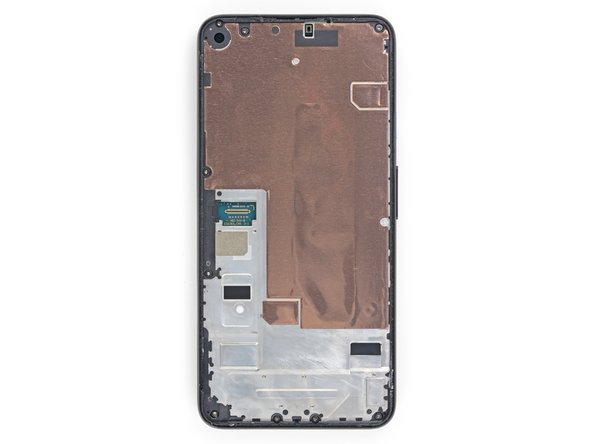
Be gentle with the copper foil; it’s as delicate as it is thin and can get punctured easily.
– Gently grab the tape with your fingers or a trusty pair of tweezers, and lift it right off that copper foil like a pro.
Tools Used
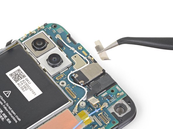
Step 28

– Use the flat end of a spudger to disconnect the front-facing camera from the motherboard.
– Remove the front-facing camera.
Tools Used
Step 29

– Grab your T3 Torx driver and carefully take out those two screws, which are 4.2 mm long, from the loudspeaker assembly. You’ve got this!
Step 30

Take care not to damage the white membranes on either side of the loudspeaker if you plan to reuse it. A little caution goes a long way!
– Slide the spudger’s tip gently under the loudspeaker assembly like you’re giving it a little nudge.
– Carefully flip the loudspeaker assembly so it’s chilling softly on top of the battery.
Tools Used
Step 31

Use your tweezers to grab the metal connector of the antenna cable— avoid the plastic cable. Keep it cool and steady!
– Grab your trusty tweezers and carefully unhook the antenna cable from the loudspeaker assembly—like a high-stakes game of Operation, but without the buzzer. Keep it steady and precise!
Tools Used
Step 32


Handle with care—those white membranes flanking the loudspeaker are delicate! If you’re planning to reuse it, avoid puncturing them like a pro.
– Gently lift the loudspeaker assembly away from the adhesive—it’s sticking around, but you’ve got this!
– Take out the loudspeaker assembly and set it aside—you’re making progress!
Step 33

– Gently use your fingers or grab a pair of tweezers to lift the antenna cable out from under the tape that’s keeping it cozy.
Tools Used
Step 34

– Carefully pry the loudspeaker cable away from the motherboard using the tip of your trusty spudger.
Tools Used
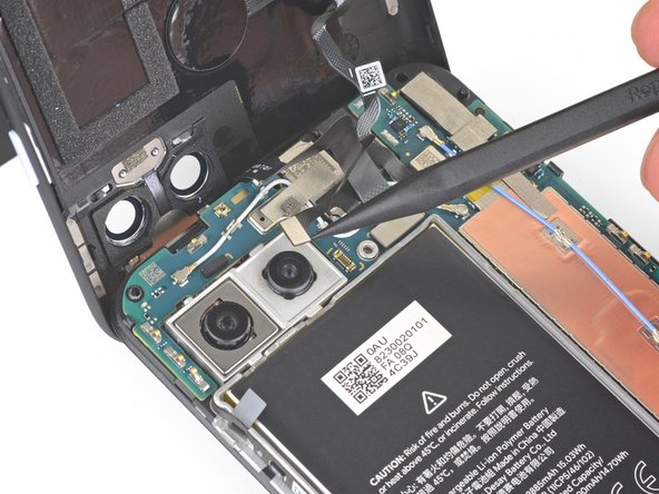
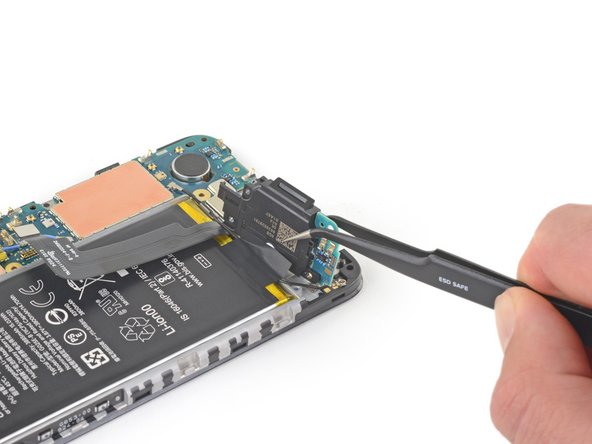
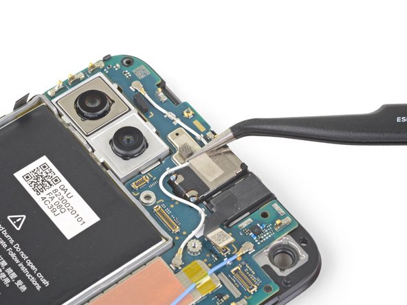
Step 35

– Gently wiggle the spudger’s tip to disconnect the headphone jack cable from the motherboard. You’ve got this!
Tools Used
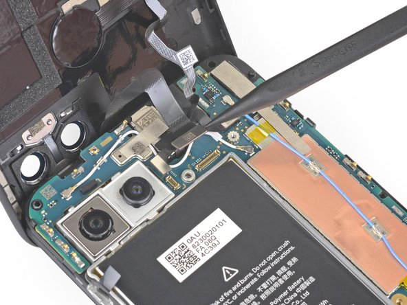
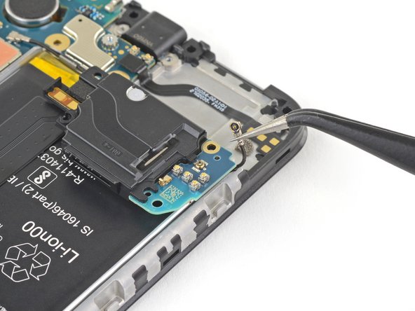
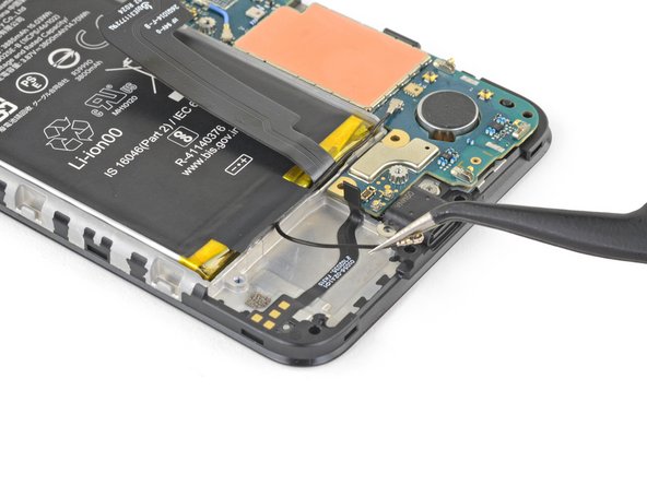
Step 36

– Grab your trusty tweezers and gently peel away the tape that’s holding the earpiece speaker snugly over the antenna flex cable. You’re doing great!
Tools Used
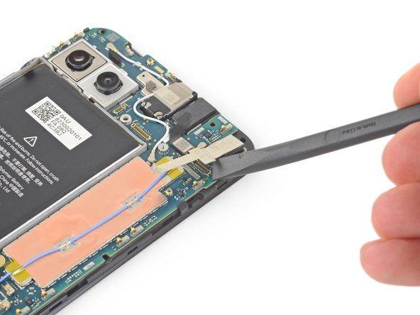
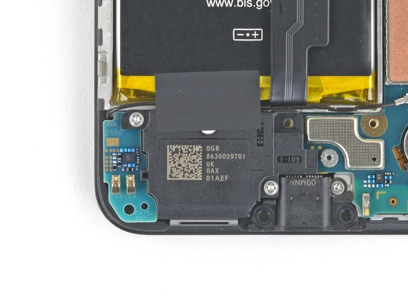
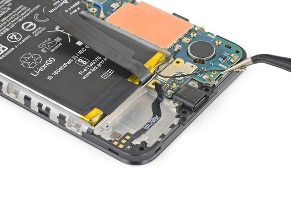
Step 37

– Grab your T3 Torx screwdriver and twist out the 2.1 mm screw holding the charging port in place. Easy does it!
Tools Used
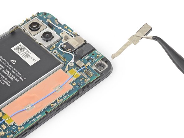
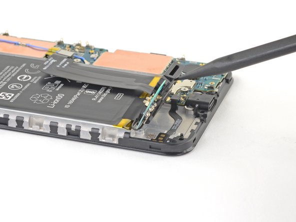
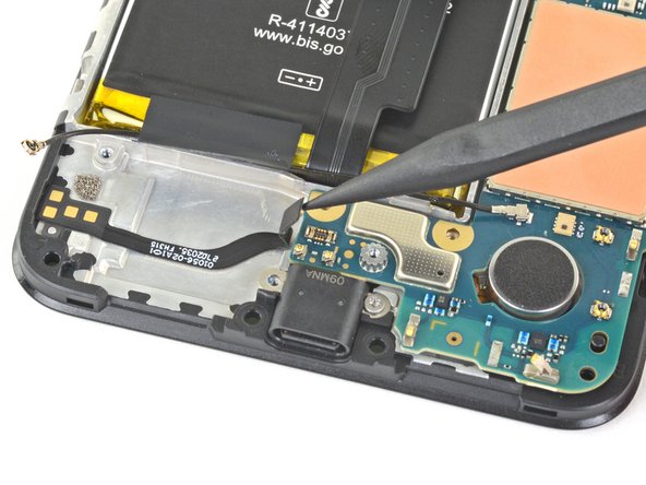
Step 38

Plastic clips are holding the motherboard snugly against the midframe, so give them a little wiggle to free it up.
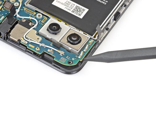
– Gently slide the tip of a spudger into the little gap between the motherboard and the midframe, right by the front-facing cameras, and nudge it to pop that first clip loose.
Tools Used
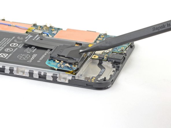
Step 39
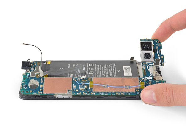
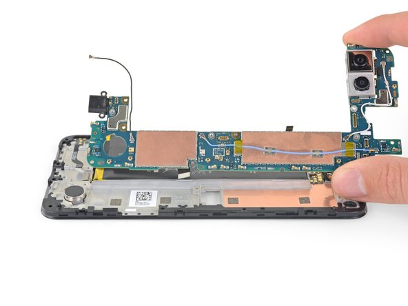

This will loosen the remaining clips.
– Gently take hold of the motherboard with your fingers and flip it open like a book.
– Carefully lift the motherboard straight up to free it from its spot.
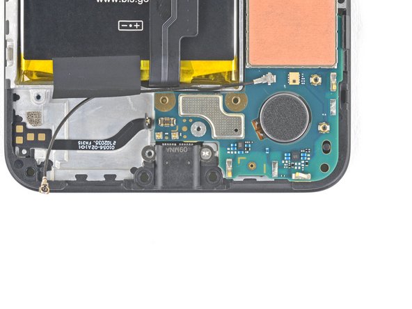
Step 40
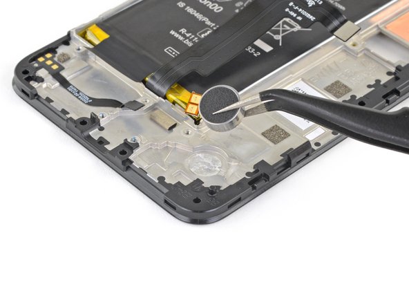

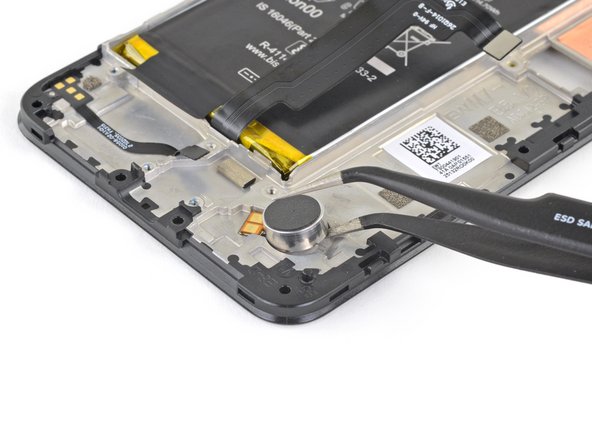
If the adhesive is a little too clingy, add a few drops of 90% isopropyl alcohol around the base of the vibrator motor. Wait about a minute to let the adhesive loosen up, and then give it another go!
The vibration motor is held in place with some gentle adhesive. Nothing too strong, but it may need a little encouragement to come free.
– To put your device back together, just work through the steps above in reverse—easy-peasy!
– Recycle your old tech responsibly at an R2 or e-Stewards certified recycler to keep our planet happy.
– Having trouble? Give some basic troubleshooting a shot, or reach out for help from our Answers community.
– If you’re still stuck, you can always schedule a repair and we’ll get you sorted!
Tools Used
Success!