Google Pixel 7a Wide Camera Replacement Guide
Duration: 45 minutes
Steps: 54 Steps
Heads up, this repair guide is a total blast created by the awesome Salvation Repair team! If you need a hand, check out our step-by-step guide or if it’s still too tricky, remember you can always schedule a repair!
Hey there, ready to tackle a wide camera replacement on your Pixel 7a? This guide will walk you through it! If your wide camera isn’t focusing or stabilizing properly, or if it’s been physically damaged (ouch!), it’s time to swap it out. Heads up: If you’ve got the Verizon model (G0DZQ) with the 5G mmWave antenna, some photos might differ, but the steps are the same. Got a swollen battery? Take care! You’ll need some fresh adhesive to complete this repair. And remember, any repair can mess with your phone’s water resistance, so make sure you reapply that adhesive like a pro.
Step 1


– Alright, let’s get started! First things first, give your phone a little break and unplug all the cables. Then, power it down completely. You got this!
Step 2


– Grab your trusty SIM eject tool, a bit, or even a straightened paper clip—whatever suits your fancy.
– Gently insert your chosen tool into the SIM card tray hole and give it a little push to pop that tray out.
– Now, carefully remove the SIM card tray and celebrate your small victory!
Step 3

Be careful not to overheat your phone – just warm it up until it’s slightly hot to the touch. Too much heat can harm the screen, rear cover, or battery, so let’s keep things gentle.
Another fun option is to grab a hair dryer, heat gun, or hot plate to give the rear cover a gentle warm-up.
– Let’s get this repair started! Apply some heat to the bottom edge of the rear cover using a heated iOpener for about three minutes.
Tools Used


Step 4


The next three steps will show you how to use the Anti-Clamp, a tool we made to help make this opening procedure easier. If you aren’t using the Anti-Clamp, just skip down three steps for a different method.
If you want to learn more about the Anti-Clamp, check out this guide.
– Give that blue handle a gentle tug backward to release the Anti-Clamp’s arms like a pro!
– Now, slide those arms right over the bottom edge of your phone, placing one suction cup on the back cover and the other on the screen. It’s like a little dance!
– Squeeze those cups together and watch as they create a snug suction. You’ve got this!
Step 5


– Gently pull the blue handle forward to give those arms a nice, secure lock.
– Now, give that handle a full clockwise turn (that’s 360 degrees of awesomeness!) or until you see those suction cups stretching out like they’re ready for a workout.
– As those cups stretch, keep an eye on their alignment. If they start to wiggle out of line, just pop off the Anti-Clamp and stick on some tape to help those cups stay put.
Step 6

While the iOpener does a great job of warming up the rear cover, it might cool off while you’re getting the Anti-Clamp ready. If you need a little extra time, just give that rear cover a quick reheat!
If the adhesive isn’t budging, give the handle a gentle clockwise twist for a quarter turn and hang tight for another minute. If the rear cover cools down again, feel free to add some more heat with a hair dryer or heat gun.
– Prop your phone on something stable so it stays level while between the Anti-Clamp’s arms.
– Hang tight for about a minute or until the adhesive lets go, creating a gap along the bottom edge of the phone.
– Slide an opening pick into the gap between the rear cover and the frame.
– Using the pull-tabs, detach the suction cups from the phone and set the Anti-Clamp aside.
Tools Used
Step 7


If you’ve already popped in an opening pick with the Anti-Clamp, feel free to breeze past this step!
– Alright, let’s get this show on the road! First, grab a sturdy suction handle and place it right smack dab in the middle of the bottom edge of that rear cover. Now, with a friendly smile and a mighty heave-ho, tug on that handle with some serious sap and voila – you’ll see a gap forming between the rear cover and its frame. Huzzah! Next, it’s time to introduce our trusty opening pick: slide it gently into the gap you’ve created. Time to bid farewell to the suction handle, my friend. And there you have it – you’re making great progress! If you need help, you can always schedule a repair.
Tools Used


Step 9


Now it’s time to get that rear cover off – just remember to keep those opening picks angled upward as you slice through, and you’ll be done in no time!
– Give that opening pick a little angle, so the tip’s pointing away from the frame, you know, like it’s saying ‘bye, Felicia’ to the phone’s case.
– Now slide that pick down to the bottom left corner of the back cover – we’re going for a smooth move here.
– Leave that pick right there, holding the fort to stop the adhesive from getting all buddy-buddy again.
Step 10


– Pop another opening pick into the bottom left corner.
– Sweep that pick to the bottom right corner of the back cover to break up the adhesive along the bottom edge.
– Keep this pick there to stop the adhesive from sticking back together.
Step 11

Or hey, if you’re feeling a bit adventurous, grab a hair dryer, a heat gun, or even a hot plate to gently warm up that rear cover. Just keep an eye on it—no one wants an overheated phone.
– Let’s give that right edge of the rear cover a warm hug from our friendly iOpener for two minutes. It’s like a relaxing spa day for your device!
Tools Used
Step 12


Don’t go crazy with that pick! Just a gentle 5mm along the right edge. You don’t want to mess with the wireless charging coil, trust us.
To help you out, try measuring 5 mm from the tip of your pick and marking it with a permanent marker. That way, you’ll have a handy visual guide to work with.
– Let’s get this party started! Insert a third opening pick in the bottom right corner of the rear cover.
– Now, slide your pick up the right edge of the rear cover to loosen that adhesive. Stop when you reach the camera bar. You’re doing great!
– Leave that pick right there to keep that adhesive from getting all cozy again.
Step 13

You can also grab a hair dryer, heat gun, or hot plate to gently warm up the rear cover. Just keep an eye on it—nobody likes a phone that’s too hot to handle!
– Time to get this repair started! Apply a heated iOpener to the left edge of the rear cover for about two minutes to loosen things up.
Tools Used
Step 14


Be careful not to push your pick in deeper than 3 mm along the left edge, or you might accidentally give the wireless charging coil and rear cover foam pad a rough time!
For a handy visual aid, measure about 3 mm from the tip and give your pick a nice little mark with a permanent marker. You’ve got this!
– Now it’s time to add a fourth opening pick to the bottom left corner of the rear cover – just slide it right in.
– Gently push your pick up the left edge of the rear cover to loosen the adhesive, stopping when you hit the camera bar.
– Leave this pick in place to keep the adhesive from resealing – you’re making great progress!
Step 15

To loosen things up, try warming the rear cover with a hair dryer, heat gun, or hot plate. Just be careful not to overheat your phone – we want to fix it, not fry it! If you’re feeling stuck, remember that Salvation Repair is here to help.
– Get your heat on! Apply a heated iOpener to the top edge of the rear cover for two minutes. This’ll loosen things up and make it easier to get in there.
Tools Used
Step 16


There’s a sturdy strip of adhesive hugging the antenna housing, just waiting for your expert touch.
If that pick isn’t sliding in easily, no worries! Try starting with the tiny gap near the camera bar from your last move.
– Wedge a fifth opening pick into the top left corner of the rear cover, between 8mm and 10mm (0.3–0.4in) deep. Aim for just over halfway between the tip of the pick and the logo.
– Slide your pick halfway across the top edge to loosen the antenna bracket adhesive. Stop when you reach the middle of the top edge.
Step 17


Keep your pick to a max of 3 mm deep to steer clear of any mishaps with the antenna housing’s graphite tape. We want to keep things safe and sound!
– Gently pull your opening pick out to about 3 mm deep. You’ve got this!
– Now, glide that pick to the top right corner and neatly slice through the remaining adhesive along the top edge.
Step 18


– Give that top edge pick a little roll so its flat edge is tucked under the rear cover. You got this!
– Roll those picks on each side of the camera bar so their flat edges are snug under that camera bar. Nice work!
Step 19


Be gentle when handling the rear cover – you don’t want to bend it. Just pry enough to loosen the adhesive near the camera bar. If it’s being stubborn, try rocking the rear cover from side to side to help loosen things up.
There’s a long strip of adhesive holding the rear cover in place just under the camera bar.
– Time to get this repair started! Use your trusty opening picks to carefully pry the top edge of the rear cover away from the frame, starting under the camera bar.
– Gently pry back and forth until the camera bar starts to loosen – you’re making great progress!
Step 20


– Gently glide those opening picks from the camera bar along the edges of the rear cover to break free any stubborn adhesive that might have reattached itself.
Step 21


– Let’s kick things off by taking off the rear cover. It’s like peeling back the layers of an onion, only less tear-jerking!
– Now, as we get ready to put everything back together:
– Here’s a pro tip: Before sealing your device back up, why not give it a quick power-up? Make sure everything is running smoothly! Once you’re done admiring your handiwork, power it back down to continue the reassembly.
– Follow this guide to apply some fresh adhesive and get that rear cover snugly back in place. You’ll be impressed with your craftsmanship!
Step 22


Be gentle when heating the flash – just warm it up so it’s comfortable to the touch. Remember, the battery and surrounding parts are heat-sensitive, so let’s keep things cool.
If you’re feeling adventurous, grab a hair dryer or a heat gun to gently warm up that flash. A little bit of heat can work wonders!
– Warm up your iOpener and give that flash unit a cozy minute of heat! This will help loosen the adhesive that’s holding it onto the logic board cover.
Tools Used
Step 23


Handle with care to avoid snagging or tearing the delicate flash cable.
– Wiggle your pick under the right side of the flash to loosen the adhesive holding it to the cover. Easy peasy!
Step 24


– If the copper tape decided to take a little vacation with the flash, grab some tweezers or use your fingers to gently clear away that pesky black foam residue from the logic board cover.
Tools Used

Step 25


Watch out for that battery! Your tool is great, but we want to keep the battery intact during this step. You’re doing awesome!
Time to get rid of that old copper tape! If it’s still stuck to the logic board cover and you’ve got a shiny new replacement, now’s the perfect time to remove the old one.
– Give the underside of the flash a cozy minute with a warmed iOpener to get things toasty.
– Keep a steady grip on the neck of the flash cable while you gently use tweezers to peel away the copper tape from the flash unit. You’ve got this!
Step 26


– Grab your trusty 3IP Torx Plus driver and get ready to tackle those thirteen 4.3 mm screws holding the logic board cover in place. You’re doing great!
– Now, switch to the 1IP Torx Plus driver to unscrew that sneaky little 1.5 mm screw on the right edge of the cover. Almost there!
Your Pixel 7a is using some fancy Torx Plus screws, but don’t worry, regular Torx drivers can still do the trick! If you’ve got a standard Torx kit, grab your trusty T2 bit for the 1IP Torx Plus screws and your T3 bit for the 3IP Torx Plus screws. Keep that pressure nice and steady, down, down, down! You don’t want to go stripping those screws, now do you?
Step 27


– Slide an opening pick into the bottom right corner of the logic board cover, sliding it gently against the frame.
– Gently pry upwards to release the clip that holds the cover in place.
Step 28


– Gently lift the top edge of the logic board cover and carefully guide the flash unit through its designated cutout.
– When putting everything back together, make sure to guide the flash through its cutout as you lower the logic board into position.
Step 29


– Gently take out the wireless charging assembly, making sure to handle it with care like it’s a precious gem!
Step 30

– Grab your trusty 1IP Torx Plus driver and carefully unscrew that 1.5 mm screw holding the connector cover in place.
– With a gentle touch, use tweezers or your fingers to lift off the cover. You’ve got this!
– When it’s time to put everything back together, make sure to tuck the upper left corner of the cover under the hook on the logic board before securing it with the screw.
Tools Used
Step 31

The Verizon model (G0DZQ) Pixel 7a comes with a nifty extra cable and connector specifically for the 5G mmWave antenna. Don’t worry though, for everything else, the repair steps are pretty much the same for both phone types. If you need help, you can always schedule a repair.
Step 32


To reconnect a press connector, line it up over the socket and give it a gentle push on one side until it clicks, then do the same on the other. It might take a couple tries to get it lined up just right.
– Time to get started! Insert the flat end of a spudger under the top edge of the battery press connector, making sure it’s securely in place.
– Now, gently pry straight up to disconnect the battery press connector – you’re making great progress!
Tools Used

Step 33

– Grab your trusty 3IP Torx Plus driver and let’s tackle that tricky 4.3 mm screw holding the earpiece speaker snugly against the frame. You’ve got this!
Step 34


– Gently lift the bottom edge of the earpiece speaker upwards. You’re getting closer!
– Carefully pull the speaker down towards the bottom of the phone – this will help the red gasket pop free from its snug little spot in the frame.
– Now, it’s time to remove the speaker completely. Almost done!
Step 35

– Time to show those screws who’s boss! Use your 3IP Torx Plus driver to loosen the two 4.3 mm screws holding the antenna housing to the frame.
– When you put it back together, keep a firm grip on the housing as you tighten those screws.
Step 36


– Slide an opening pick into the top left corner where the antenna housing meets the frame—just a little nudge will do!
– Gently pry upwards to free those pesky clips holding the housing tight. You’ve got this!
– When putting everything back together, make sure to keep that graphite film out of the way so the housing can slide right in.
Step 37


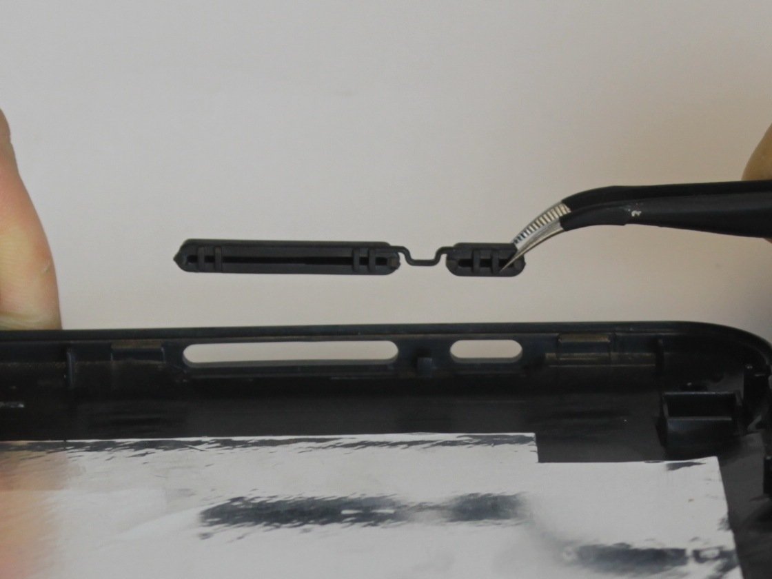
– Gently lift the bottom leg of the antenna housing and carefully wiggle the top edge free from the frame.
– Now, go ahead and remove the housing!


Step 39

If you’re feeling crafty, a hair dryer or heat gun can work wonders to loosen that adhesive. Just warm up the tape until it feels cozy to the touch!
– Give the front-facing camera a warm hug with a heated iOpener for about a minute. This will help loosen that pesky copper tape adhesive, making your repair journey smoother!
Tools Used
Step 40


Watch those rear camera lenses like a hawk! They’re sensitive little things, so let’s keep our fingers off them.
If the tape seems to be playing hard to get, grab a sharp tool like angled tweezers and gently nudge the edge of the tape until there’s a little space for a pick to slide underneath. Just take your time and you’ll get there!
– Gently slide the tip of your trusty opening pick beneath the shiny copper tape near the front-facing camera.
– Carefully lift that tape away from the logic board like you’re unwrapping a gift!
Tools Used
Step 41


Watch out for that front-facing camera lens! Keep your tool clear so it stays safe and sound.
If the pick can’t slip under that pesky cable, why not give it a warm woosh with a hair dryer? This’ll make the adhesive all mushy and easy-peasy for your pick to slide right under! Gotta make it fun, right? 😉
– Gently slide the tip of your trusty opening pick right between the front-facing camera cable and the frame—think of it as giving it a little nudge.
– Now, glide your pick under that cable just like you’re spreading butter on toast, carefully separating it from the adhesive that’s holding it tight to the frame.
Tools Used
Step 42

Watch out for those shiny rear camera lenses – they’re delicate little things!
The connector we’re looking at here handles some pretty important jobs – it’s in charge of your power button, volume buttons, flash unit, and upper microphone.
– Gently use the tip of a spudger or your trusty fingernail to lift up and disconnect the press connector located just above the battery. You’ve got this!
Tools Used
Step 43

– Slide your opening pick between the top right edge of the logic board and the frame. Give it a little wiggle to make it happy.
– Now, gently pry up to free the logic board from its cozy little recess.
– Slide your pick into the gap near the white antenna cable and give the top left edge of the logic board a little lift. You got this!
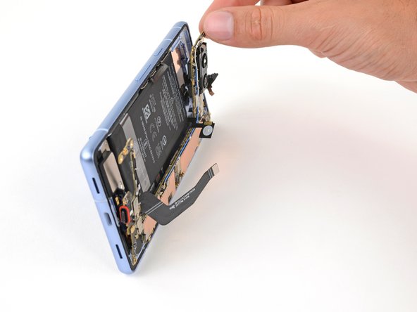
Step 44


Be gentle with that logic board – it’s super delicate, so try not to bend it as you work it free from the frame.
Not so fast! Don’t completely remove the logic board just yet, it’s still hooked up to the frame by the screen cable.
Keep an eye on that flash, front-facing camera, and press connector—they don’t want to get stuck under the frame!
– Gently raise the top edge of the logic board from its snug home in the frame.
– With a little finesse, slide the top edge of the logic board to the right, so those nifty cutouts glide over the vibration motor and any pesky protrusions in the frame.
– As you shimmy it out, make sure to guide the charging port free from its cozy little recess.
– When it’s time to reassemble, give that logic board a little nudge toward the bottom of the frame, and press the charging port down until its bottom edge lines up perfectly with the frame’s protrusion.
Step 45

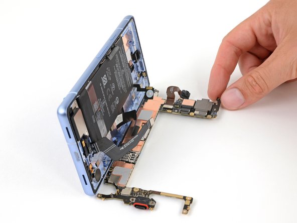
Watch out! The logic board might decide to do its own thing and slip out of place during this step. Keep it secure, but be gentle—no squeezing those delicate camera lenses or connectors!
Steer clear of the thermal pads hiding on the bottom of the logic board. They’re a bit touchy, so just let them be.
If you’re lacking a suction handle, no worries! Just lean your phone against something solid, like a hefty box or a thick book. You’ve got this!
– Grab your trusty suction handle and give that left side of the screen a gentle kiss, with the handle facing down like it’s going for a victory lap!
– Now, let’s get this phone standing tall and proud like the champion it is!
– Time to give that logic board a friendly nudge, tilting it down like it’s wave surfing on a summer day. Lay it flat, move any cables to the side, and watch as everything falls into place.
Tools Used
Step 46


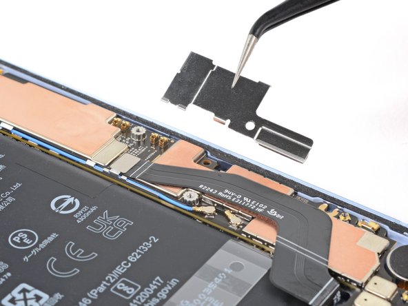
– Grab your trusty 3IP Torx Plus driver and carefully remove the 2mm screw that’s holding the screen connector cover in place.
– Now it’s time to take off the cover – easy does it!
– When you’re putting everything back together, make sure to hook the bottom edge of the cover into its slot on the logic board before screwing it back in.
Step 47


– Grab that trusty spudger and gently pry up to disconnect the screen press connector. You’re doing great!
– Now, reconnecting that sneaky cable can be a bit tricky since it’s got some serious tension. If it gives you a hard time, just hold the cable’s neck steady with some tweezers and align it perfectly over the socket before giving it a firm press to secure it. You’ve got this!


Step 49

Try not to touch the sensor with your fingers or tools, folks!
– If the front sensor rubber gasket decided to stick around on the frame or got a bit out of whack, gently take it off and put it aside for now.
– When it’s time to put everything back together, just pop the gasket over the front sensor on the logic board, making sure the smaller cutout is facing up. You’ve got this!
Step 50

– As you get ready to piece everything back together, here’s the scoop:
– If you’re using your old logic board and the thermal pad looks a bit worse for wear, no worries! Just peel off that old pad, give the surface a good clean, and pop on a shiny new thermal pad.
– If you’ve got a brand new logic board that’s come pad-less, now’s the time to stick on that fresh thermal pad. You got this!
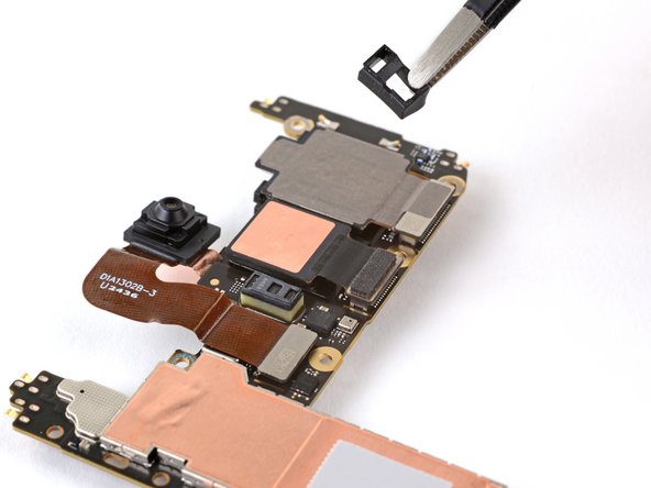
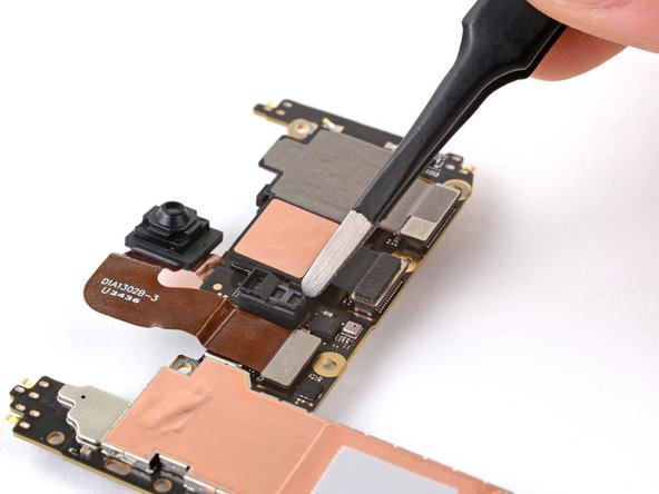
Step 51

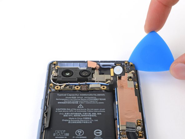
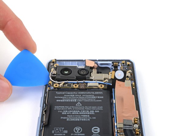
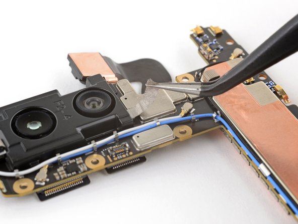
– Grab your trusty spudger and gently slide the flat end in there to lift up and disconnect both rear camera press connectors from the logic board. You got this!
Tools Used
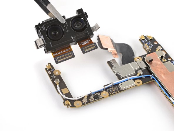
Step 52

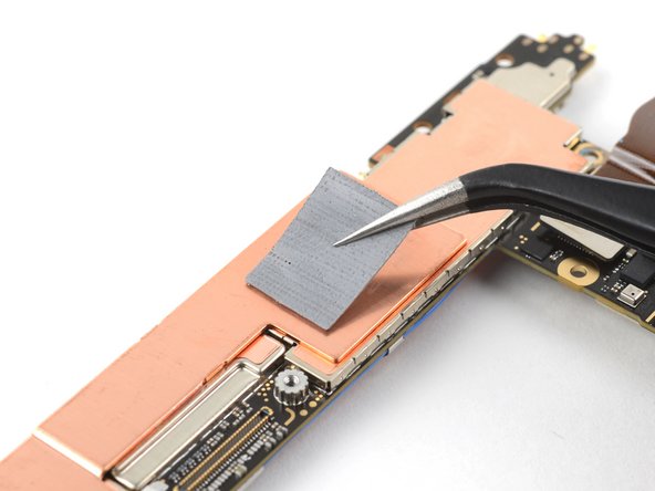
Before you start, give your work surface a quick once-over. If it’s dirty or uneven, grab a towel or a lint-free cloth and use it as a protective layer for the logic board. This will help keep it safe and scratch-free.
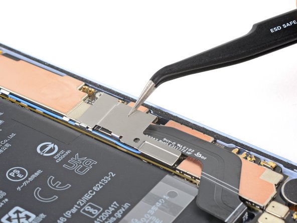
– Turn the logic board around.
– Grab your tweezers and gently lift the silver conductive fabric connecting the rear camera bracket to the logic board.
Tools Used
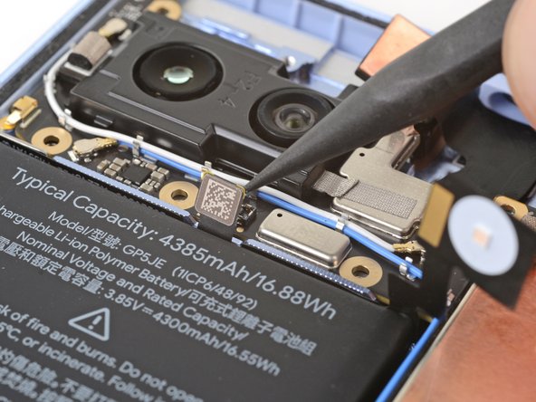
Step 53

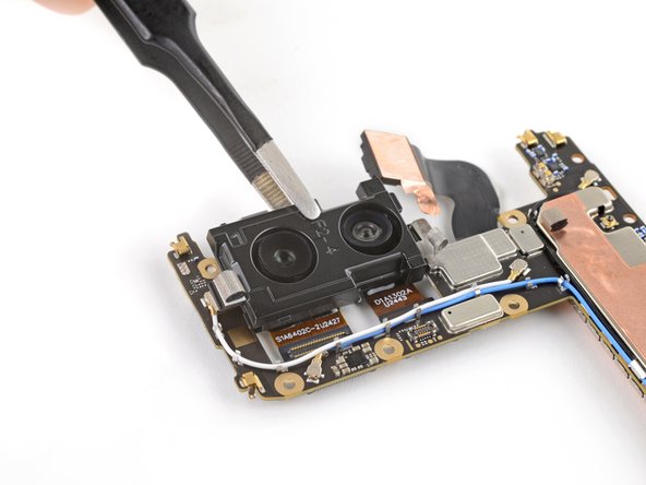
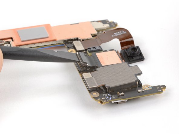
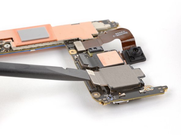
– Time to give that rear camera assembly the boot! Carefully remove it, but be gentle with the camera lenses – those are delicate little things.
– Now, get ready for a little assembly line action! When you’re putting everything back together, make sure the assembly is angled downward so the press connectors slide under the logic board, and the tab on the left of the bracket is above the logic board. You got this!
Step 54

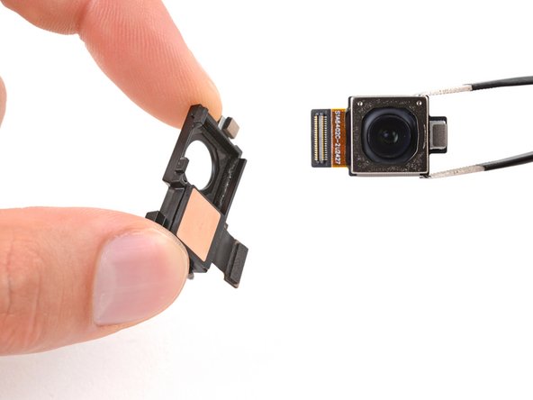
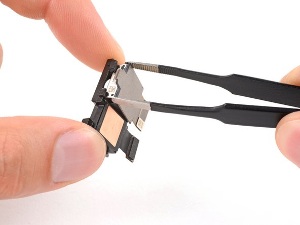
The wide camera is stuck to the rear camera bracket, so let’s get it unstuck.
– Now that you’ve conquered this repair, put your device back together by reversing the steps you just took. Easy peasy, right?
– Want to give your tech a checkup? You can run a diagnostics test using the built-in Pixel Diagnostic tool, but don’t worry if it seems a bit technical – you’ve got this!
– Recycle your old parts responsibly at an R2 or e-Stewards certified recycler. It’s good for the planet, and makes you a super awesome tech hero!
– Things not going as smoothly as you hoped? Don’t sweat it! Try a little troubleshooting, or ask for a helping hand from our Answers community. We’re here to cheer you on!
– Didn’t finish the guide? No worries, you can always come back to it later!
–
Tools Used
Success!