Google Pixel Fold Base Vibrator Replacement
Duration: 45 minutes
Steps: 63 Steps
This repair guide hasn’t been endorsed, but it’s super helpful and accurate. Learn more about our repair guides and process at Salvation Repair.
This handy guide is here to help you swap out the base vibrator in your Pixel Fold! While this guide was put together by the awesome team at Salvation Repair, it’s not officially linked to any big names. Ready to get your repair on? Let’s dive in! If you need help, you can always schedule a repair.
Step 1

Make sure your battery dips below 25% before diving into this repair adventure. A battery that’s still charged might throw a fiery tantrum if it gets hurt!
– Power down your phone completely and unplug any cables before diving in.
Step 2

You can try using a hair dryer, heat gun, or hot plate to warm things up, but heads up—too much heat might mess with the screen or battery. So, take it easy and keep it chill while heating!
– Place your phone on a clean, flat surface with the back glass facing up. Make sure there’s plenty of space to work around it.
– Warm up an iOpener and gently press it against the bottom edge of the back glass for about two minutes. This will help loosen things up a bit for the next steps.
Tools Used

Step 3


The next few steps introduce the Anti-Clamp, a nifty tool we created to simplify the opening process. If you’re not using the Anti-Clamp, just skip ahead three steps for a different method.
Want to know exactly how to use the Anti-Clamp? Check out this guide for all the details.
Make sure the suction cup on the inner screen isn’t touching the bezel, or it won’t stick as well.
If the surface of your phone feels too slick for the Anti-Clamp to grip, try using tape for extra traction. And if the glass is cracked, packing tape can help the suction cups stick better.
– Gently pull the blue handle back to free the Anti-Clamp’s arms.
– Completely unfold your phone and slide the Anti-Clamp arms over the left edge of the back glass, just below the logo.
– Place the suction cups close to the bottom edge of your phone—one on the front and one on the back.
– Press the cups together to create a solid suction on the area you want to work on.
Step 4


– Set your phone on something sturdy like a box or a stack of books so it stays steady between the Anti-Clamp’s arms.
– Slide the blue handle forward to lock those arms in place.
– Turn the handle clockwise a full 360 degrees or until you see the suction cups start to stretch.
– Keep an eye on the suction cups—if they start to slip out of sync, pop them off and realign the arms before continuing.
Step 5

Take it easy! Only twist a quarter turn at a time, and chill for a minute between each turn. Let the Anti-Clamp and a little patience do their magic!
If the Anti-Clamp isn’t creating enough space, no worries—just add a bit more heat to the area and give the handle a quick quarter-turn to get things moving.
– Gently slide an opening pick into the tiny gap beneath the back glass.
– Feel free to breeze past the next step.
Step 6


Got a back glass that’s seen better days? Slap on some clear packing tape—it can help the suction cup stick like a champ! If you’ve got some super strong tape lying around, that could be your MVP instead. And if all else fails, get creative and use a little superglue to stick that suction cup to the busted glass.
Phones can play hard-to-get, especially older ones! If you’re hitting a roadblock, crank up the heat around the edges (carefully!) and give it another go.
– Stick a suction cup on the back glass, aiming for the center of the bottom edge.
– Give that suction cup a solid pull to open up a little gap between the back glass and the frame.
– Slide an opening pick into that gap you’ve created.
Step 7


Keep the opening pick no deeper than 3.5 mm when sliding through the back glass adhesive—going deeper might poke around where you don’t want to and cause some internal mischief.
– Gently wiggle the opening pick side to side along the bottom edge to loosen that sticky adhesive.
– Keep the pick snug in the bottom left corner before moving on to the next step.
Step 8

– Warm up your trusty iOpener and place it on the left edge of the back glass for about two minutes to get things moving. You’ve got this!
Tools Used
Step 9


– Swing that opening pick around the bottom left corner like you’re cutting through butter to loosen up the adhesive.
Step 10


– Place an opening pick at the bottom left corner—like a pro!
– Slide it smoothly toward the top left corner to break free the adhesive.
– Leave the pick in place at the top left corner so it can keep the separation steady while you move forward.
Step 11

– Place a warm iOpener on the top edge of the back glass and let it work its magic for two minutes.
Tools Used
Step 12


– Swing that opening pick around the top left corner like a pro to ease the adhesive apart.
Step 13


– Pop in a third opening pick at the top left corner, and get ready to make some magic happen!
– Gently glide that pick toward the top right corner to break the adhesive seal. You’re doing great!
Step 14

– Heat up an iOpener and gently press it against the right edge of the back glass for about two minutes. Let the warmth do its magic to loosen things up before moving forward.
Tools Used
Step 15


That sharp corner is a bit delicate! Use lots of heat and be super gentle as you work around it. Patience is key here—slow and steady wins the race!
– Hold your pick nice and flat against the back glass, like you’re sneaking it under the door.
– Gently twist the pick around the top right corner to loosen up that stubborn adhesive.
Step 16


– Place a fourth opening pick in the top right corner, making sure it’s snug but not too tight.
– Gently slide the pick down toward the bottom right corner to start separating the adhesive. Take it slow and steady!
Step 17


This corner is delicate and not a fan of rough handling! Warm it up generously and go easy—you want finesse, not force.
– Get your pick ready and angle it super flat against that back glass – you’re about to get cozy with some adhesive
– Gently rotate your trusty pick around the bottom right corner – time to start separating that stickiness and making some progress
Step 18


Hold up! Don’t go yanking off that back glass just yet—it’s still hanging on by a cable. Let’s be gentle here!
By now, the back glass should be fully freed from the frame. But if it’s still putting up a fight around the edges, grab an opening pick and gently persuade any lingering adhesive to let go.
– Gently flip the left edge of the back glass up and over to meet the right edge of the phone—like a secret handshake between old friends.
– Rest the back glass to the right side of the phone for now. It’s taking a quick breather before we move on to the next step!
Step 19

As you dive into this repair adventure, remember to keep an eye on those little screws! They love to play hide and seek, so make sure they return to their cozy spots when you’re done.
The Pixel Fold may be rocking Torx Plus screws, but don’t sweat it—standard Torx bits are totally on board too! Just grab the same size or one size up (T3 or T4 Torx bits paired with those 3IP Torx Plus screws), and give it a steady push downwards to keep everything intact and avoid any stripping mishaps.
– Grab your Torx Plus 3IP driver and unscrew those two 2.8 mm-long screws holding the middle bracket tight.
Step 20


– Grab your tweezers or just your fingers, and gently tug the middle bracket toward the left side of the phone to pop its clip free.
– Take out the middle bracket.
– When putting it back, slide the middle bracket clip under its slot in the frame first, then line up the screw holes before tightening.
Tools Used

Step 21


Alright, let’s get those connectors back in action! Start by gently aligning one side and pressing down until you hear that satisfying click. Then, give the other side a little love tap too. Just a heads up—avoid pressing in the middle! If things get a bit wonky and the connector misaligns, those precious pins can bend and that’s not a good look. Keep it neat to avoid any permanent damage!
– Grab your trusty spudger and gently wedge the tip under the back glass cable—it’s time to pop it loose from the motherboard. Stay steady, take your time, and let the tool do the work!
Tools Used

Step 22

– Take off the back glass carefully. It might need a little finesse, but with the right touch, it’ll come off smoothly.
Step 23


No custom adhesive strips? No worries—grab some double-sided tape like Tesa Tape and stick that back glass to the frame like a pro.
– When you’re piecing everything back together:
– Grab some trusty tweezers and pluck away those stubborn chunks of adhesive hanging around the edges of your back glass—it’s time to evict them!
– Repeat the process for any leftover adhesive hanging out on the frame. No freeloaders allowed!
– Bust out some high-proof isopropyl alcohol (at least 90%) and a lint-free cloth to wipe away every last trace of sticky residue. Clean glass, clean conscience.
– Check out this guide for placing custom-cut adhesive strips to get your back glass looking fresh and secure.
Tools Used
Step 24


Handle the graphite sheet with care—it’s delicate! Take it easy while peeling it off, especially if you’re planning to reuse it.
The graphite sheet is gently stuck onto the logic board, so take it easy when handling it.
– Start by gently peeling the bottom of the graphite sheet upwards, working your way toward the top of the phone, until the bottom bracket is revealed.
– To keep the graphite sheet out of the way, you can either use your hands or lightly stick some tape on it. Just make sure it stays clear while you work.
– When you’re putting everything back together:
– If you’ve removed the entire graphite sheet, be sure to follow the guide to put it back in place.
– Don’t have pre-cut adhesive strips for the antenna? No problem—just use some double-sided tape (Tesa Tape works great!) to secure the graphite sheet to the logic board.
Step 25


– Grab some tweezers or use a clean fingernail to gently pop off the black screw cover hiding the top screw on the bottom bracket.
Tools Used
Step 26

– Grab your trusty Torx Plus 3IP driver and carefully unscrew the five 3.1 mm screws holding down the bottom bracket. You’ve got this!
Step 27


– Grab some tweezers (or your trusty fingers) and gently pull the bottom bracket toward the edge of the phone. Give it a little nudge to release the clip.
– Now, carefully remove the bottom bracket and set it aside.
– When you’re putting things back together, don’t forget to slide the bottom bracket clip back under its slot on the logic board before lining up the screw holes. Everything needs to fall into place, like a puzzle!
Tools Used
Step 28


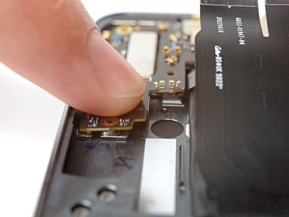
Alright, here’s the deal—your phone’s got two batteries, one for each half, and they both need to be unplugged. Time to work your magic!
– Grab the tip of your trusty spudger and gently lift up to disconnect that pesky base battery cable press connector.
Tools Used
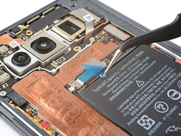
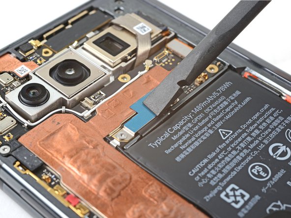
Step 29


– Carefully peel away the grey conductive tape from the bottom interconnect cable—slow and steady wins the race!
Step 30


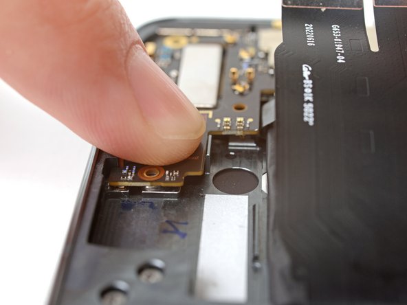
Make sure to unplug both cables so the battery connector doesn’t accidentally make a surprise visit to the logic board.
– Grab a spudger and gently pry up to disconnect the flip battery and the bottom interconnect press connectors. You’ve got this!
Tools Used
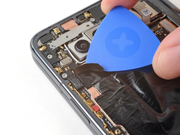
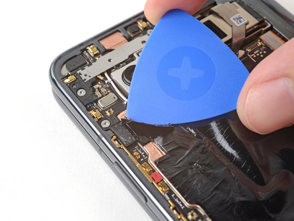
Step 31


– As you put everything back together, the next two steps will show you how to swap in that flip battery and the bottom interconnect cable’s conductive tape.
– Carefully peel the new conductive tape from its backing and stick the adhesive side onto the bottom interconnect connector, ensuring it connects across the logic board like a pro!


Step 33

– Gently slide an opening pick beneath the top edge of the graphite sheet to free up that thermal insulator adhesive. You’re on the right track!
Step 34


– Gently peel away the graphite sheet from the logic board to free up any stubborn adhesive that’s still hanging on.
– Carefully take out the graphite sheet.
Step 35

– Got some leftover adhesive? Grab your tweezers and gently peel it off the logic board. It’s like giving your device a little spa treatment—nice and easy.
Tools Used
Step 36


Pry carefully with your spudger—don’t risk damaging that battery by being too aggressive,
– Slide the flat end of a spudger between the battery and the bottom speaker—time to work some magic.
– Give the spudger a gentle twist to loosen up that adhesive holding the bottom speaker in place.
– Lift out the bottom speaker like a pro and set it aside.
– When you’re putting everything back together, check if your adhesive is still tacky and usable. If it’s not, follow this guide to replace it.
– Out of custom adhesive strips? No worries! Grab some trusty double-sided tape, like Tesa Tape, and secure the speaker snugly back onto the frame.
Tools Used
Step 37


Alright, tech wizard, take it slow here! Those tiny surface-mounted components on the logic board? They’re basically the VIPs of your device, and they do NOT appreciate rough treatment. Keep your tools away from the logic board—no prying allowed!
– Time to get a little more personal with your device! Use the pointy end of a spudger to gently pry up and disconnect the fingerprint sensor press connector. You got this!
Tools Used
Step 38


– Carefully lift off the tape that’s securing the top interconnect cable—like unveiling a secret connection!
Step 39

– As you get ready to put everything back together, here’s how to swap out that conductive tape:
– Start by peeling the new conductive tape from its backing, and stick the adhesive side onto the press connector, ensuring it connects nicely with the logic board.
– Grab a spudger or simply use your fingers to press down the conductive tape, making sure it sticks well.
– Now, take some tweezers or your fingers to gently pull on the tab and reveal the tape.
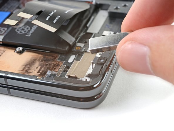
Step 40

– Let’s get started by removing the two screws that hold the top interconnect cable in place. Grab your trusty Torx Plus 3IP driver and get to work!
– You’ll find one 2.8 mm-long screw waiting for you – remove it with care.
– And don’t forget the second screw, which is 2.5 mm long. Out it comes!
Step 41


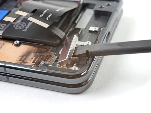
The metal bracket holding the connector is actually a part of the press connector itself. So, let’s keep that bracket where it is and not try to take it off!
– Gently use the tip of a spudger to lift and disconnect the top interconnect cable press connector. Take your time, it’s like giving the connector a little hug before sending it on its way.
Tools Used
Step 42


Handle this step with care to avoid accidentally damaging the tiny components on the logic board. Remember, no prying on the logic board!
– Gently pry up and unplug the inner screen press connector using the flat end of your trusty spudger.
– Carefully swing the inner screen cable up 90° and tuck it over the right edge of the phone before moving on.
Tools Used
Step 43

– Grab your trusty Torx Plus 3IP driver and unscrew the two 2.8mm-long screws holding the middle bracket in place.
Step 44


– Slide the top bracket gently toward the left edge of the phone to pop its clips free.
– Lift off the top bracket.
– When putting it back, tuck the top bracket clips under their slots in the frame first, then line up the screw holes before securing.
Step 45

The 5G mmWave antenna is lightly stuck to the frame. It’s not going to put up a huge fight, but be gentle when peeling it off to avoid any issues.
– Gently slide the tip of a spudger between the frame and the right edge of the 5G mmWave antenna.
– Carefully pry upwards to break the adhesive seal.
– When putting everything back together, if your adhesive is still holding strong, feel free to reuse it! If not, check out this guide to swap in some fresh adhesive.
– No custom adhesive strips? No problem! Just grab some double-sided tape, like Tesa Tape, to keep that antenna snug against the frame.
Tools Used
Step 46


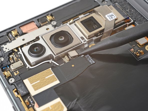
Keep that spudger right where it needs to be—no wandering! Stray too far, and those tiny surface-mounted components on the logic board might not appreciate the surprise.
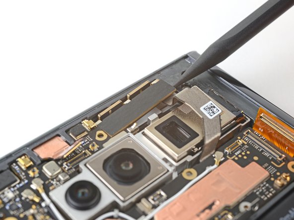
– Slide the tip of your spudger under the bottom-right corner of the front camera press connector, like a pro.
– Gently pop it up to disconnect the front camera press connector—nice and easy!
Tools Used
Step 47

The front camera is firmly attached to the frame, so you’ll need to ease it out with some care.
A hair dryer or heat gun can help loosen the adhesive, but keep it moving—don’t overheat the phone or hold the heat in one spot for too long.
– Warm up an iOpener and give the front camera some TLC—press it down for a solid two minutes.
Tools Used
Step 48


Be gentle with those press connector pins; a little pinch could bend them out of shape!
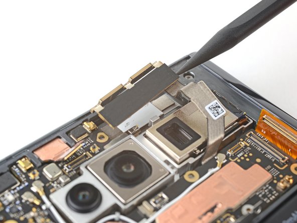
– Grab those tweezers and get a hold of the front camera by its connector—stay close to the camera body for maximum grip.
– Lift straight up with confidence to break free the adhesive and remove the front camera—no need to wrestle with it!
– When putting things back together, check if your adhesive still has some sticky magic left. If yes, reuse it. If not, follow this guide to swap it out.
– No custom adhesive strips? No biggie! Just use some trusty double-sided tape, like Tesa Tape, to stick the front camera securely to the frame.
Tools Used
Step 49


– Grab your trusty Torx Plus 3IP driver and let’s tackle those screws holding the logic board in place:
– First up, there’s a 2.8 mm-long screw hanging out near the top left corner, just waiting for you to remove it.
– Then, don’t forget the 2.5 mm-long screw chilling near the bottom right corner. It’s your last little buddy to unscrew!
Step 50


Avoid bending the cables too sharply; you don’t want to end up with a permanent crease in them.
– Grab some tape that won’t fight back—like painter’s tape—and gently secure these three cables so they stay put while you work your magic:
– Fingerprint sensor cable
– Top interconnect cable
– Inner screen cable
Tools Used

Step 51


– Slide the flat end of your trusty spudger right under the top edge of the logic board, close to where the front camera hangs out.
– Gently pry upwards to pop the logic board free from its top alignment peg—smooth moves only!
Tools Used
Step 52


Take your time with this step—seriously! The logic board is delicate, and the frame has all these little cutouts you’ve got to navigate. Be gentle, go slow, and if it feels stuck, don’t force it.
As you tackle this step, you might notice a little resistance from the white logic board bracket. Just lift gently until it pops out of its cozy spot in the frame.
You may also feel a bit of tugging from the thermal paste that’s sticking the logic board to the frame. You’re doing great—keep at it!
– Grab the top part of the logic board with your fingers.
– Gently lift the logic board upward while sliding it a bit toward the right side of the phone to pop loose the bottom clip.
– Once that clip is free, lift the board straight up to free it from the lower alignment peg.
– Pull the logic board out carefully.
Step 53


Time to give that logic board some love! Grab the flat end of a spudger and spread the new thermal paste evenly—think of it like buttering toast, but way more important. Aim to match the original spread for optimal heat dissipation.
– Time to clean up that thermal paste during reassembly—no shortcuts here!
– Make sure to follow this guide to get that thermal paste re-applied like a pro.
– Grab the flat end of a spudger and scrape off the old thermal paste from the bottom of the logic board—precision is key!
– Wipe away any leftover residue using isopropyl alcohol (>90%) with a coffee filter or a lint-free cloth. No gunk left behind!
– Repeat the cleaning process for the thermal paste on the frame—because a thorough clean means top-notch performance!
Tools Used
Step 54

– Alright, let’s get that logic board back in place! The next four steps will guide you through it—no sweat.
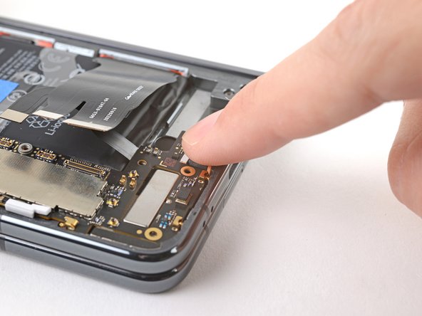
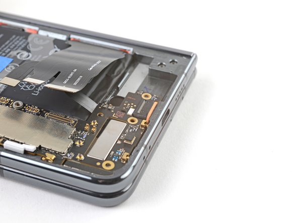
– Ease the USB-C port into its cutout in the frame at a slight angle, like a smooth landing.
– Give it a gentle press with your finger to settle it in—make sure the orange rubber gasket sits snug and level, not twisted or pinched.
– Line up the bottom of the logic board with its lower alignment peg and pop it into place, engaging those spring connectors like a pro.
Step 55

– Gently nudge the logic board toward the bottom edge of the phone while pressing it into its lower metal clip. A little finesse goes a long way—get it snug without forcing it!
Step 56


– Give that white logic board bracket a firm press so it tucks neatly under the lip along the frame’s edge—like sliding a puzzle piece into place!
Step 57


Double-check that all cables are neatly resting above the logic board before snapping it back into place. If you haven’t taped them down yet, now’s the time—this little move keeps you from accidentally trapping any wires as you go!
– Hold down the white logic board bracket while sliding the logic board toward the left edge of the phone.
– Align the logic board with the top peg to make sure it’s in the right spot.
– Give it a firm press to lock the logic board into place.
Step 58

– Alright, time to free that graphite sheet! If it’s taped down, go ahead and peel that tape off—liberate the sheet and let it breathe.
– Grab your trusty spudger and get surgical—gently pry up and disconnect the ultra wideband antenna press connector. Precision is key here, so take your time!
Tools Used
Step 59


The ultra wideband antenna is gently stuck to the graphite sheet.
– Gently slide an opening pick beneath the antenna to loosen its sticky bond.
Step 60


– Gently lift the ultra wideband antenna and take it out.
– When putting things back together, if the adhesive is still tacky and holding strong, you’re good to reuse it. If not, here’s the plan for swapping it out.
– No custom adhesive strips on hand? No worries! Grab some double-sided tape, like Tesa Tape, to stick the antenna back onto the logic board.
Step 61

A hair dryer, heat gun, or hot plate can help loosen adhesive, but too much heat is a recipe for disaster—think fried displays and unhappy batteries. So, go easy and keep it cool!
– Give your iOpener a warm-up and then place it on the base vibrator for a cozy two minutes.
Tools Used
Step 62

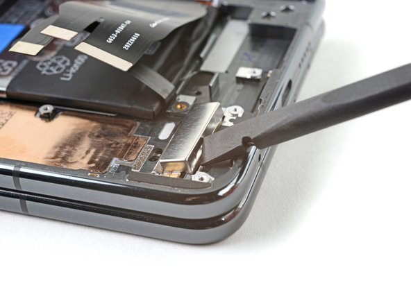
– Slide the flat end of a spudger between the vibrator’s base and the frame.
– Give the spudger a little twist to open up a gap.
– Wiggle the flat end of the spudger into that gap—steady does it!
Tools Used
Step 63

– Recycle your e-waste responsibly by taking it to an R2 or e-Stewards certified recycler.
– Match your new part with the original one carefully—you might need to move over some bits or peel off adhesive backings before installing.
– Put everything back together by working through these steps in reverse order.
– Want to check if everything’s working right? Run a diagnostics test using the built-in Pixel Diagnostic tool.
– If things didn’t go as expected, try some basic troubleshooting, or if you’re stuck, you can always schedule a repair.
–
Success!
