Hitron CODA Teardown
Duration: 45 minutes
Steps: 15 Steps
Product Number: 1504300014V0
Step 1

– Start by gently peeling off those rubber covers. They’re stuck on with a bit of weak glue, so they’re pretty easy to pop off. Just a heads up – the two at the back have screws hiding underneath.
– Grab a screwdriver and unscrew those screws to move on to the next step.
Step 2


– Plastic tabs are chilling all around where the top and bottom of your case meet.
– I found the easiest move is to start prying along the sides of the back—go slow and steady.
– Keep working your way around until the case pops apart and the top half swings up and forward like a champ.
Step 3

– Ethernet switch: Check out the Realtek RTL8363SC family—datasheet 1, datasheet 2, and the programming guide are your go-tos for all the details.
– Ethernet magnetics: Bothhand/Pulse Electronics LG2P109RN datasheet—because every connection deserves a good vibe.
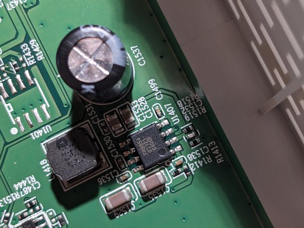
– Step-down converters (2x): The Fitipower FR9854 datasheet has your back for these power moves.
– Serial NOR SPI flash (16Mb): Macronix MX25U1633FM2I datasheet and flash dump—don’t let your data get lost in the shuffle.
– eMMC: Phison PS8211-0 details 1, details 2, details 3—triple the info, triple the confidence.
– LED driver: Give your lights some love with the Rohm BD2651MWV sibling datasheet 1.
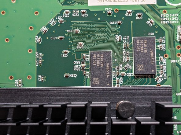
– DRAM (2x 2Gb): Samsung K4B2G1646F-BYMA datasheet and product page—memory matters, and these links tell you why.
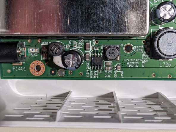
Step 4

Go easy—pulling too hard could pop the processor right off.
– Give the ends of the heatsink legs a gentle squeeze with your pliers, then pull them back through the holes in the circuit board.
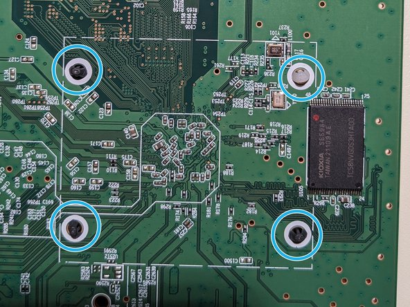
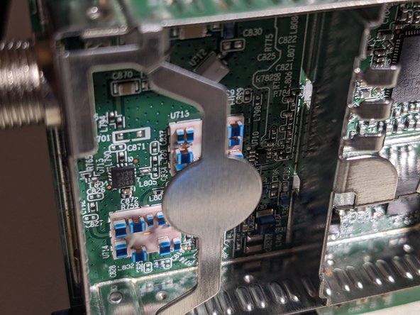
Step 5
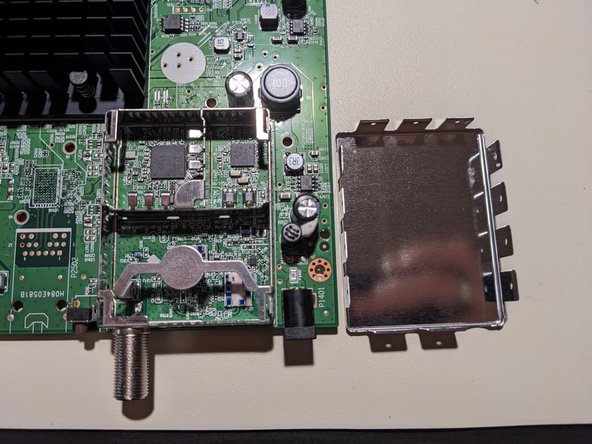

– Gently pop up the little tabs all around the shield’s edge.
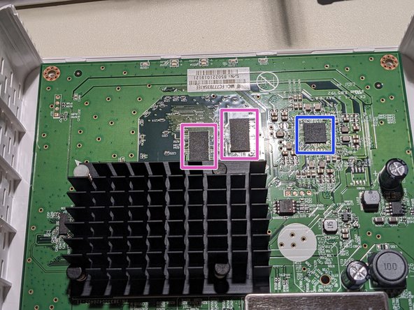
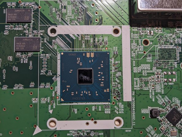
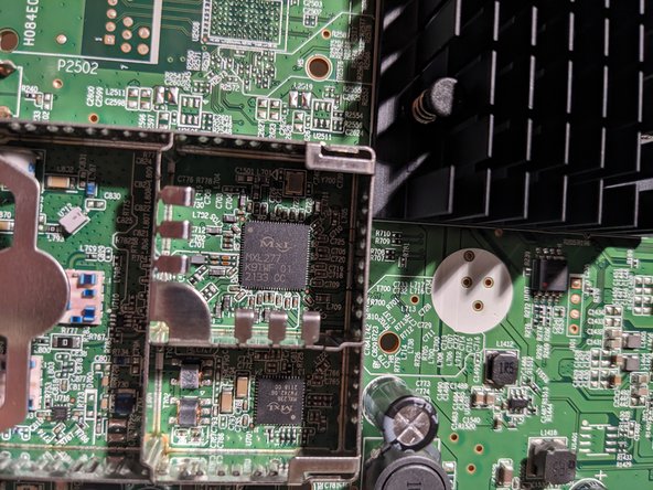
Step 6

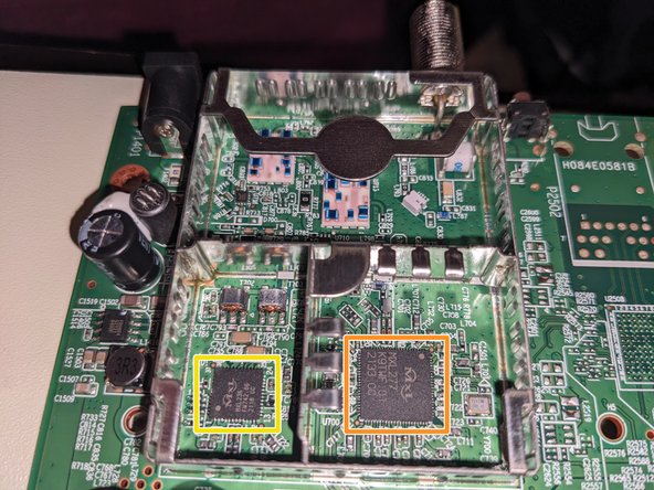
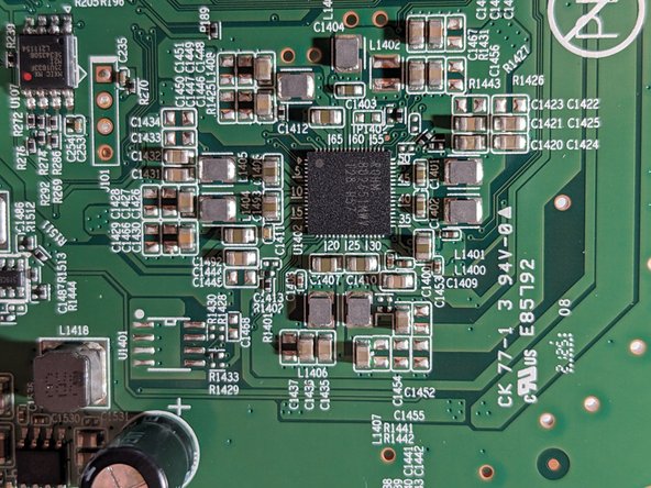
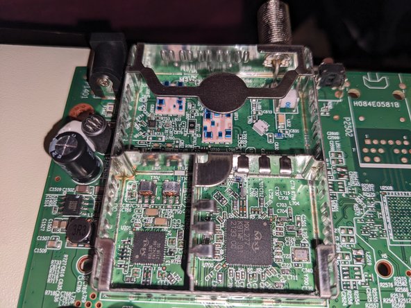
– Main chip: Intel FHCE2703 SR3SA (Puma 7) – check out its specs for more details
– DOCSIS cable tuner: MaxLinear MxL277 – get the scoop on the product page
– DOCSIS upstream amplifier: MaxLinear MxL236 – see what it can do on the product page
Step 7

– Grab your screwdriver and unscrew those pesky screws.
– Carefully lift the PCB away from the case, and you’re on your way!
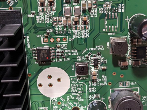
Step 8

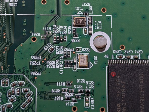
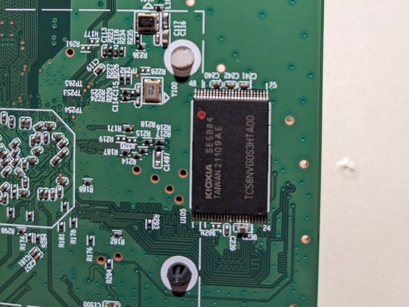
– Serial NAND EEPROM (1Gb): Check out the Kioxia TC58NVG0S3HTA00 datasheet for all the juicy details.
– Got a debug header? It’s there to give you access to the factory firmware bootlog, so make sure to check it if you’re troubleshooting.
– Once your modem’s plugged into the cable network, your ISP will automatically update the firmware to a version optimized for their network. This update follows the DOCSIS spec, specifically the ‘SwUpgradeFilename’ option in the config file. Cool, right? Get the full scoop if you need more info.
– Here’s the thing: after my modem upgraded to the Xfinity firmware, it stopped sharing the bootlog through the UART debug header (yep, even with a logic analyzer attached or not—just to confirm). So, that might be something you need to watch for.
– Pro tip: The debug headers usually have a silkscreen arrow pointing to one of the pins. The pin on the opposite side, the farthest from the arrow, is the ground pin. Easy to spot, right?
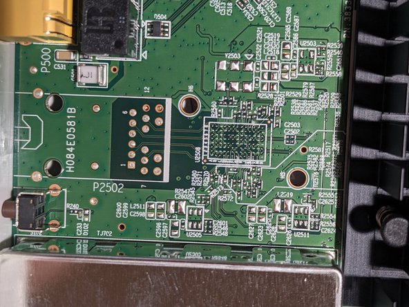
Step 9

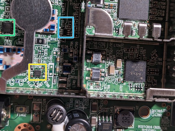
– Product number 383300420402-11
– Unpopulated connector H084E0581B
– Various test points (labeled ‘TPXXX’)
– 602 910
– V39 3601 2049
– U710
Step 10

– A little know-how goes a long way—let’s get your device back in shape!
Step 11

– Now it’s time to add some wisdom! Take a deep breath and get ready to make this repair smooth and easy. If you’re feeling uncertain, remember, it’s totally okay! You’ve got this. But hey, if things get tricky or you’d rather have a pro handle it, you can always schedule a repair.
Step 12

– Start by powering off your device and removing any protective cases or accessories. Gather your tools, including a pry tool and small screwdriver set. If you need help, you can always schedule a repair to get professional assistance.
– Carefully insert the pry tool between the device’s case and the screen or back cover. Gently work your way around the edges to loosen the clips—patience is key here. Remember, a little gentle pressure goes a long way.
– Once you’ve loosened the clips, lift the cover or screen slowly. Be cautious of any cables or components attached—disconnect them carefully if needed. If at any point you’re unsure, don’t hesitate to schedule a repair for expert help.
– With the cover removed, locate the component you wish to replace or repair. Follow the manufacturer’s instructions or repair guide step-by-step to ensure safe removal and installation.
– After completing the repair, reconnect any cables or components, then carefully snap the cover or screen back into place. Make sure all clips are secured evenly.
– Power on your device to test that everything is working correctly. If you encounter any issues, remember, professional repair services are just a click away.
Step 13

– Alright, let’s get started! Grab your tools and let’s jump in. Take a deep breath—this is going to be smoother than it looks. Keep it steady, and we’ll have this repair done before you know it!
Step 14

– Here’s a handy tip for you: Take your time, don’t rush. The key to success in this repair is precision and a steady hand. You got this!
– Step one: Let’s start by gently prying open the device. A little patience here goes a long way. Use a plastic tool to avoid any unnecessary scratches, and if it gets tricky, just breathe and take a moment. You can always schedule a repair if needed.
– Next, carefully disconnect the internal components. It might seem like a lot of wires, but just take it step by step. Don’t force anything. If you’re unsure at any point, you know where to find help.
– Now, you’re on the home stretch! Double-check all your connections before sealing everything back up. Everything should feel snug, but don’t overtighten. Confidence is key!
– Once everything’s back in place, give it a test run. Power it up and check that everything works as expected. If you notice something off, you might want to revisit the earlier steps—or again, schedule a repair.
Step 15

– Drop your knowledge bombs here!
Success!