Honda Miimo HRM300 2013 Teardown
Duration: 45 minutes
Steps: 27 Steps
Check out these quick and easy Honda Miimo HRM 300, 310, 500, and 520 cover and setup tips—no sweat necessary!
Need a hand with your HRM310 or HRM520? Here’s a step-by-step look at setup—let’s make it a breeze.
Blades feeling a little tired? This guide will walk you through a smooth swap on your HRM310 or HRM520.
And for those curious about bearings and wheels, we’ve got you covered with clear, relaxed instructions.
Let’s crack open the Honda Miimo HRM300 robot mower (Type: HRM300 – EAE MAWF 1003989, 2013) and see what makes it tick! We’re on the hunt for RTK GPS project potential—think OpenMower vibes. If you’re curious about covers, blades, or what’s hiding under the hood, check out the linked YouTube videos for hands-on tips and tricks. The info also covers the HRM 310, 500, and 520 models, so you’re in good company. If you ever get stuck, you can always schedule a repair.
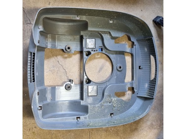
Step 1


– Flip the device over so it’s upside down.
– Gently bend those snappy white tabs to loosen up the cover.
Step 2


– Unplug that cable and give it some space!
– Unscrew those screws from the suspension and let’s get this party started!
Step 3

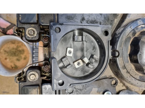
– No need to worry about removing this part, it’s all good where it is.
– I cleaned 1 out of 3 components – one step closer!
Step 4

– Here’s where you put your expertise to good use. A little patience goes a long way here, so take your time, follow the steps, and before you know it, you’ll be one step closer to having your device up and running like new.
Step 5

– Time to channel your inner tech whisperer. Let’s dive in, one step at a time, and get this device back in action!
Step 6


– Drop some knowledge on yourself right here.
Step 7


– Get ready to dive into this repair adventure! Follow these steps closely, and you’ll be back up and running in no time. Remember, every great repair starts with a little bit of patience and a sprinkle of humor. If you hit a tricky spot, don’t hesitate—if you need help, you can always schedule a repair.
Step 8


– Drop some knowledge here and get ready to dazzle with your repair skills.
Step 9

– Time to get your hands dirty (in the best way possible)! Make sure everything is powered off, because we don’t want any accidental surprises. Powering down is your first move to avoid trouble later on.
Step 10

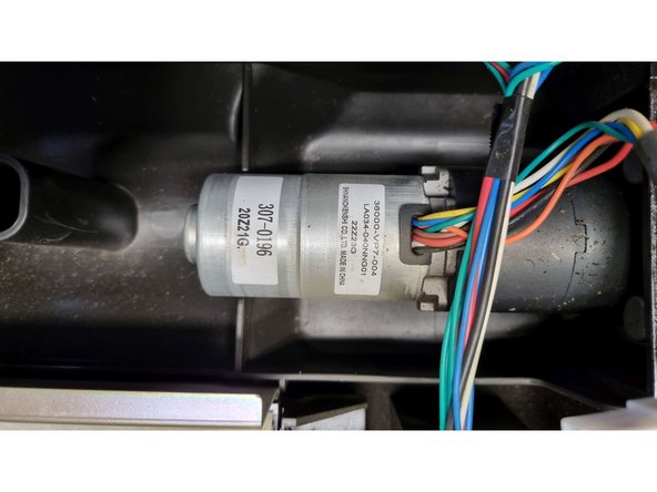
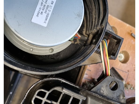
– Motor details: 36000VP7004, LA034-040NNG01, 8 wires, SHINANOKENSI.
– Couldn’t track down the datasheet, but SHINANOKENSI seems to go by Aspina Group these days. Check their site for any updates: https://www.aspina-group.com/en/contact/. Their catalog lists LA052-040 as a similar inner rotor brushless DC motor.
– This looks like a brushless DC motor setup—3 phase drive wires, 3 HAL feedback wires, one for power (vcc), and one for ground.
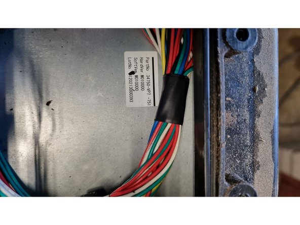
Step 11


– Four wires: red, black, white, and a slim blue one (for that extra flair).
– Battery specs: 1800mAh, 22.2V, and a punchy 40Wh.
– Power type: lithium ion—reliable and ready for action.
– Product details: Original Artikel Nr.: 31520-VP7-C10, swaps in for Artikel Nr.: 31520-VP7-751, compatible with HRM300 and HRM310.
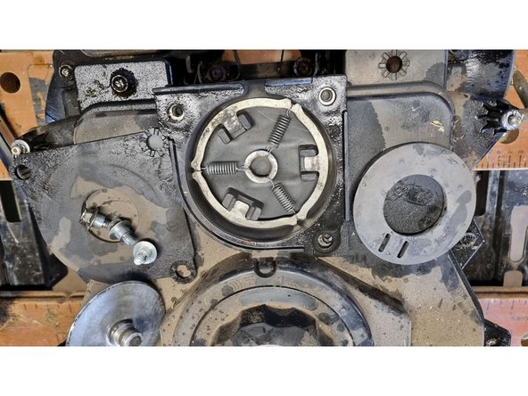
Step 12

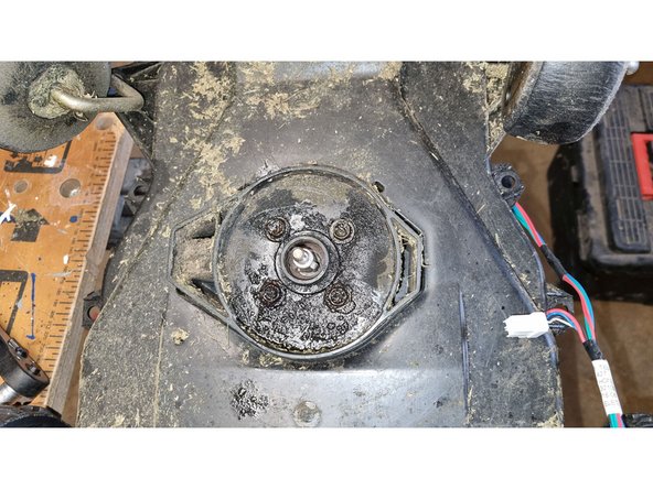
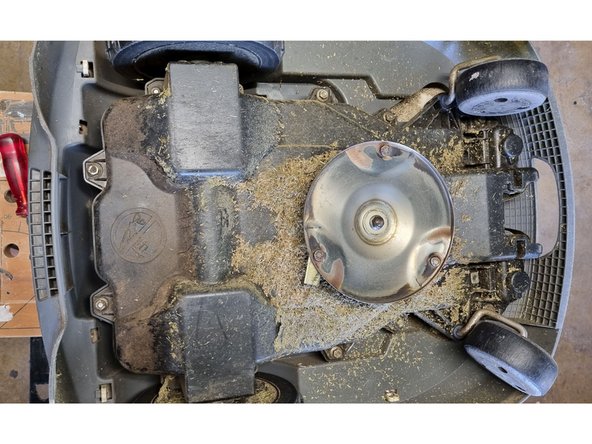
– Grab your 25mm wrench and use it to secure the shaft beneath the blade-holding disk. It’s a bit like giving the parts a solid handshake!
Step 13

– Time to put your repair hat on!
Step 14

– Drop some knowledge here!
Step 15
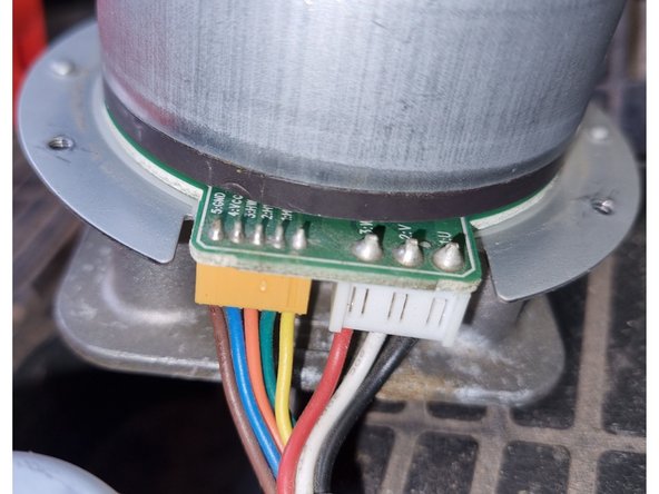

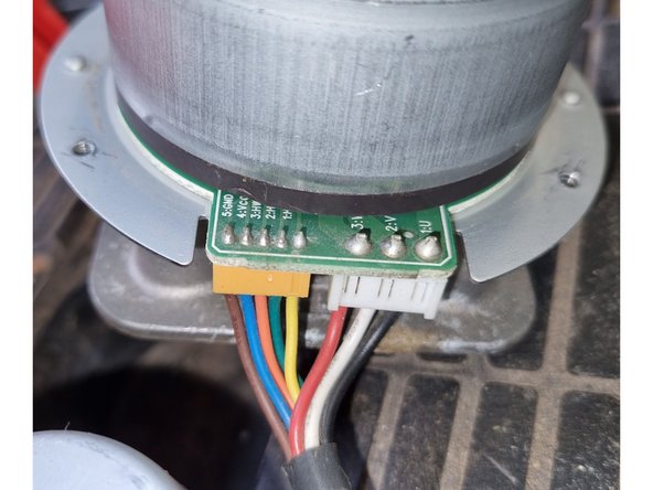
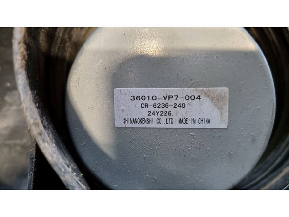
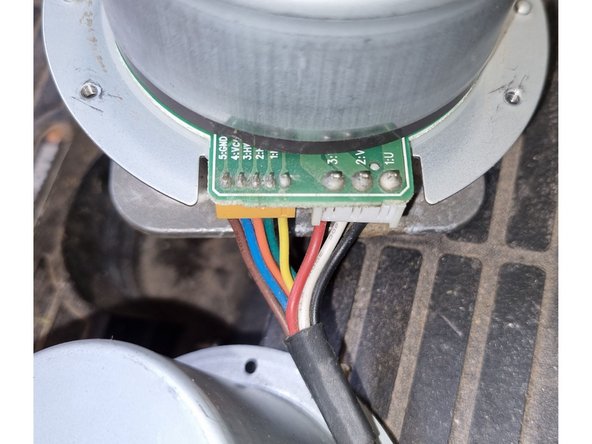
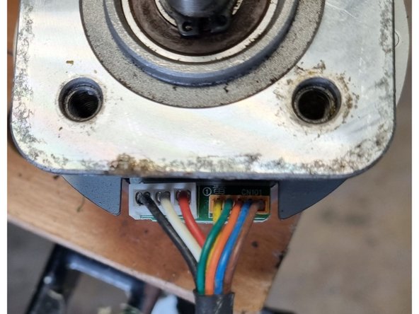
– Here’s the scoop: you’re working with about 8 wires, likely for a DC brushless motor—think of it as the motor’s secret handshake. Pin 1 maps to U, pin 2 to V, and pin 3 to W. On the other side, it’s labeled HU, HV, HW, VCC, and GND—think of these as the motor’s social security numbers. For detailed specs, check out the product page at this link. The marking ‘DR-6236-249’ from Shinanokenshi probably now belongs to Aspina Group—just like a name tag in the tech world. If you need help along the way, you can always schedule a repair.
Step 16

– Bring your A-game and let’s get this repair party started! Follow these steps and you’ll have your device back in tip-top shape in no time. If you run into any tricky spots, don’t sweat it—just remember, you can always schedule a repair to get some expert help.
Step 17

– Ready to give your device a fresh start? Let’s get started! First, power down your device completely to keep things safe. Then, carefully remove any screws or clips holding the back cover in place—think of it as opening the door to your device’s inner world. Gently pry open the cover, making sure not to use too much force. Inside, locate the component you need to replace or repair. Follow this step-by-step, making sure each part is handled with care. If you run into trouble or need a hand, you can always schedule a repair with Salvation Repair for expert assistance.
Step 18

– Alright, time to dive in and get your device back to its former glory! Just follow the steps below, take it slow, and don’t worry—you’ve got this! If something feels a little too tricky, feel free to schedule a repair, and we’ll take care of it for you. Otherwise, let’s keep moving forward!
Step 19

– Share your knowledge here with a sprinkle of fun!
Step 20

– Time to show that device who’s boss!
Step 21

– Share your repair wisdom here—any clever tips, tricks, or motivational words you’d want future fixers to know. Don’t be shy!
Step 22


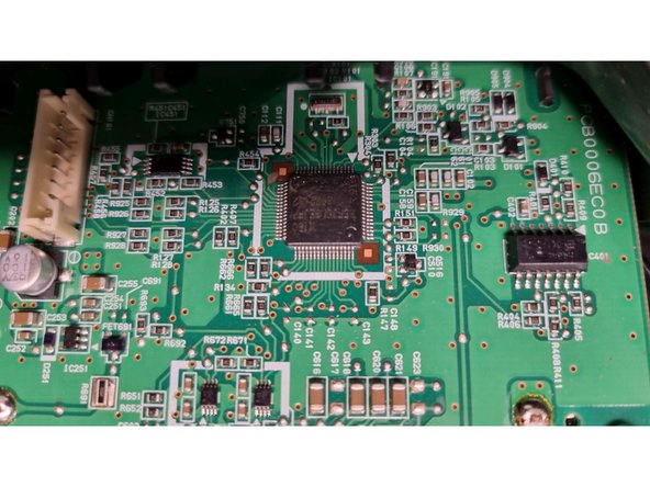
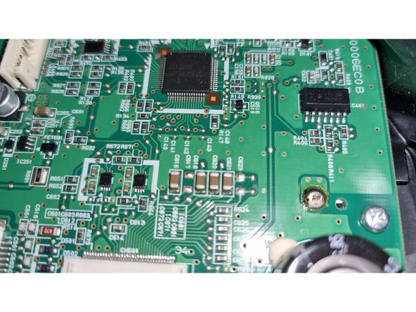
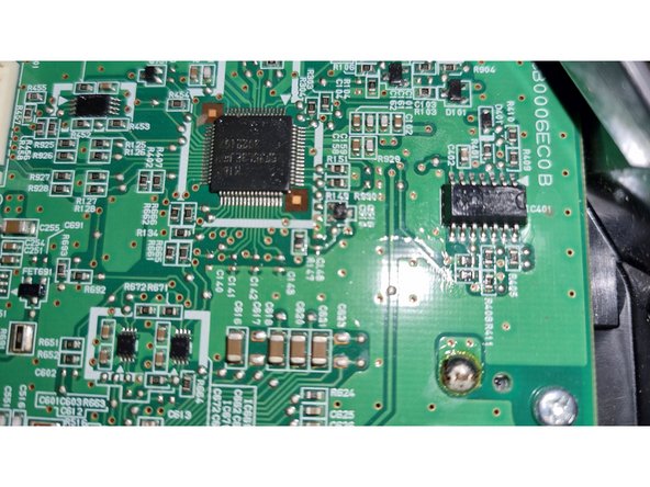
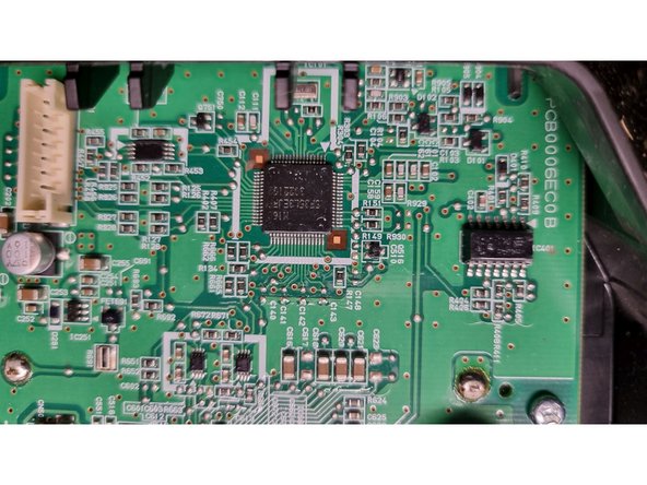
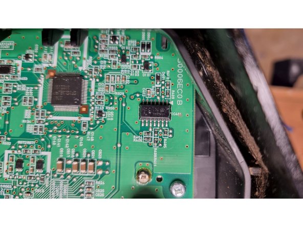
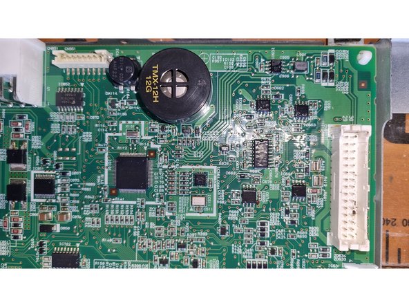
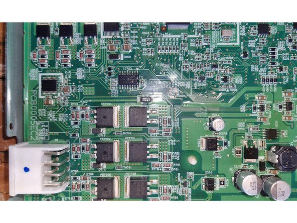
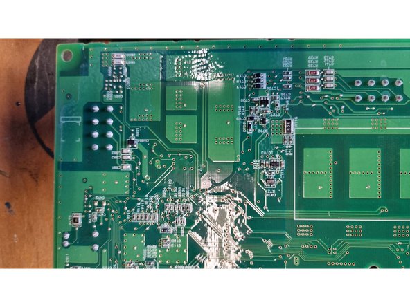
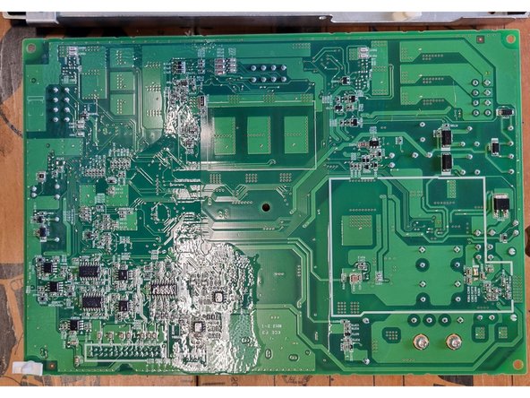
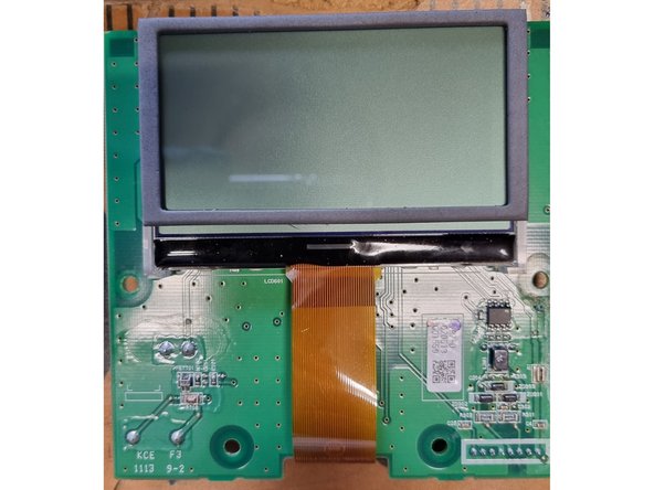
– Hold it up to the light and you’ll notice it has that dual-layer PCB look.
Step 23

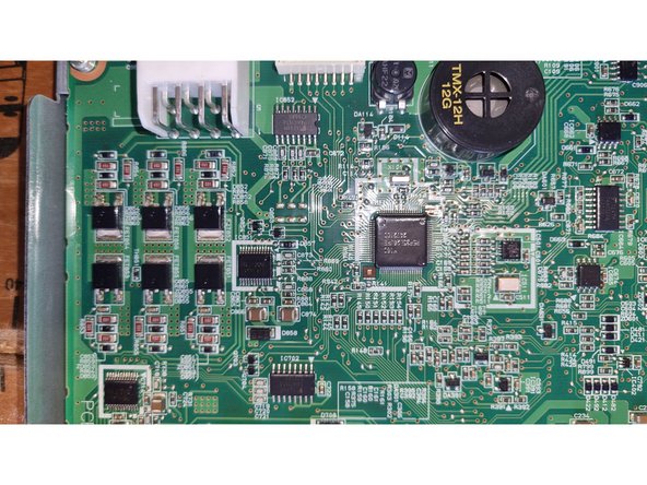
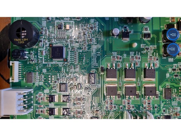
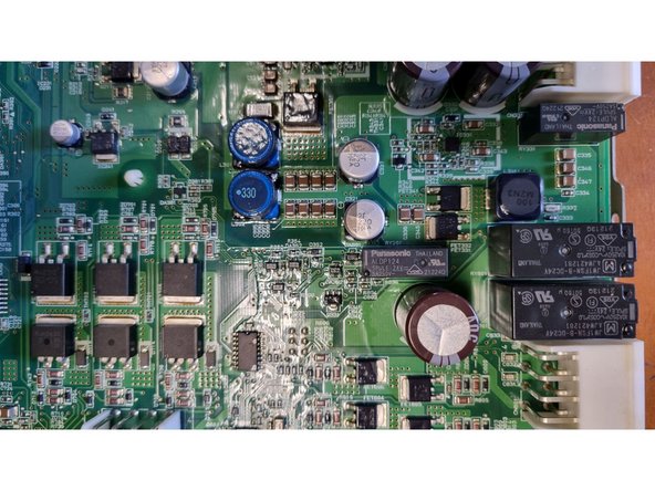
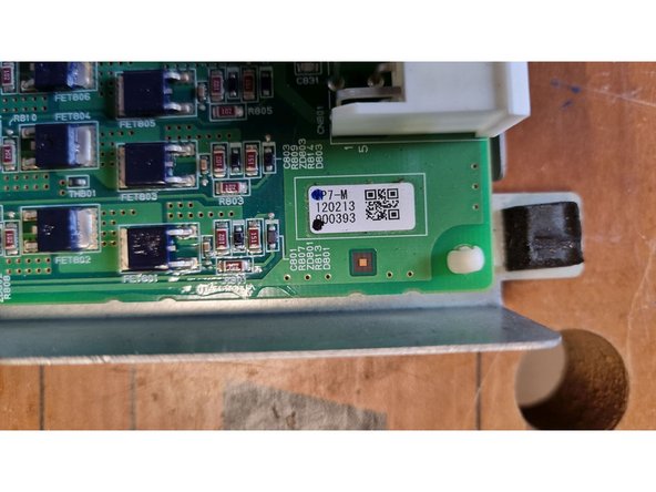
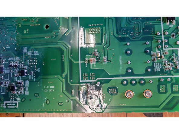
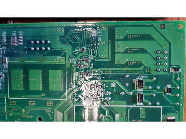
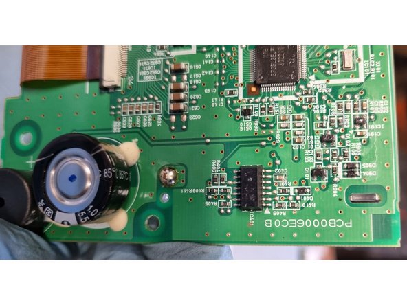
– silicon heat transfer to metal shield for probably the motor cutter driver
Step 24

– Here’s your repair wisdom: take a deep breath, trust your skills, and let’s get this device back in action!
Step 25

– Apply a water-resistant coating to keep things dry and extend the life of your device. It’s like giving your gadget an umbrella—just a little protection goes a long way!
Step 26

– Add a sprinkle of knowledge here!
Step 27

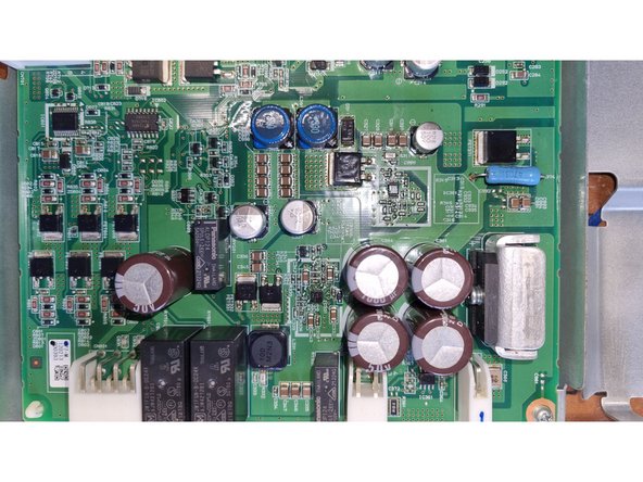
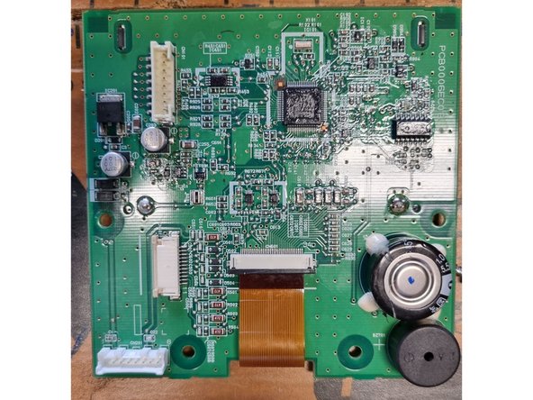
– Looks like you’re working with a 4-layer PCB—just a heads-up, there are a few extra layers tucked in there!
Success!