How to Apply Liquid Metal in a PlayStation 5 DIY Repair Guide
Duration: 45 minutes
Steps: 45 Steps
Hey there, tech warrior! Need a hand? No worries! If you need help, you can always schedule a repair. Let’s get to fixing that gadget!
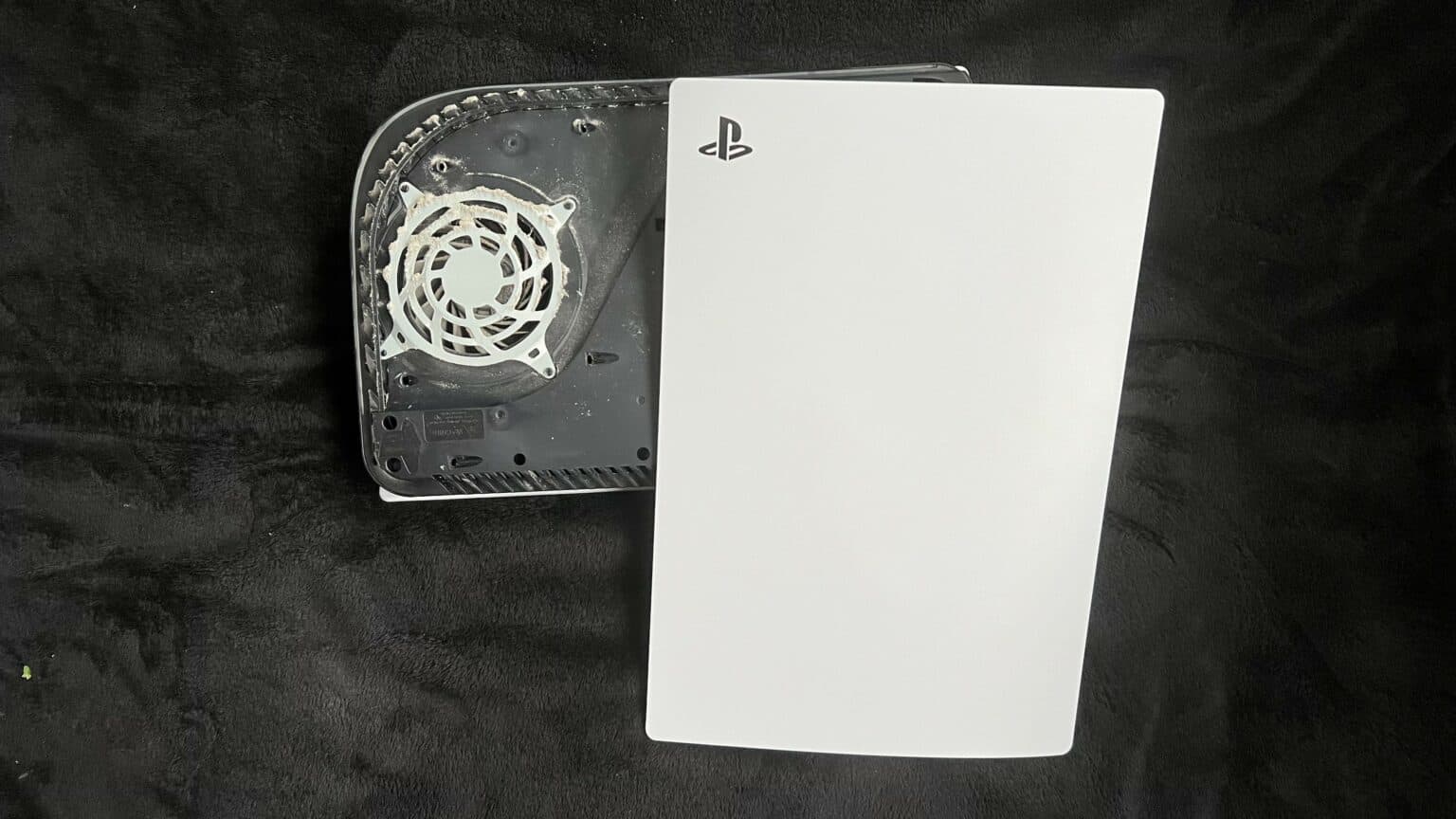
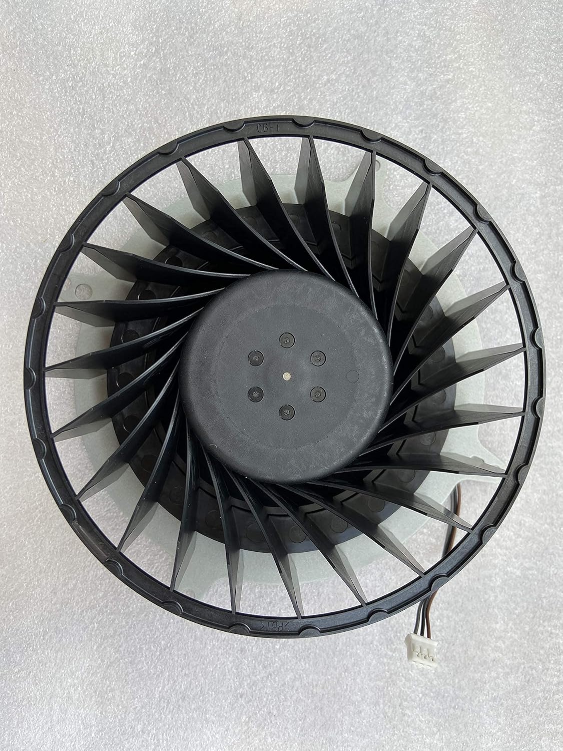
Get ready to amp up your PlayStation 5! This guide is your ticket to applying liquid metal like a pro. Whether you’re reviving existing liquid metal or starting fresh, your PS5’s APU is in for a treat. Say goodbye to the old-school thermal paste and hello to cutting-edge thermal interface material (TIM). If your liquid metal is showing signs of wear from standing upright too long, it’s time to show it some love. Watch out for that oxidized, cracked look—it’s a sure sign to roll up your sleeves and get cleaning. If things are just a bit lopsided, a smooth, even spread is all it takes to get back in the game. If your PS5 is feeling the heat, acting sluggish, or throwing a tantrum, it might be time for a liquid metal makeover. And remember, a cranky fan could also be to blame. When it’s time to give your fan a breather, follow this handy guide to keep things cool.
Step 1

Make sure you’re working on a nice, flat surface so your PlayStation stays put and doesn’t take a tumble!
Ready to make things right with your PlayStation 5? If it’s lounging horizontally, jump ahead to Step 6 and let’s get this party started!
– Got your PS5 standing tall? Flip it upside down so the stand is on top.
– Grab a coin or a flathead screwdriver and unscrew that 26.5 mm-long stand screw.
Tools Used

Step 2


– Lift straight up to remove the stand. Easy peasy!
Step 3


– Gently place the tiny screw into the cozy slot at the base of the stand.


Step 5


– Give the stand a friendly twist to the left to close the cubby. Need a hand? schedule a repair
Step 6


– Got your PlayStation 5 chillin’ horizontally? Gently lay it down with the charging port facing up, like it’s catching some rays on a sunny day.
– Next up, grab the stand and give it a little lift straight up to bid it farewell.
Step 7


– Turn your device upside down so the USB and ethernet ports are on your left side. Easy peasy!
– Gently lift the corner of the faceplate to pop it off the case. You’ve got this!
Step 8


– As you delicately lift up the corner, gently glide the faceplate downwards on the device.
– Bid farewell to the right faceplate as you remove it.


Step 10


– Gently lift the grille off the case to set it aside.
Step 11

As you work on this repair, keep a watchful eye on each screw. Put them back exactly where they came from, so your console stays happy and healthy. If you need help, you can always schedule a repair.
– Grab your trusty TR8 Torx security driver and let’s get to work! Start by unscrewing the four screws that are holding the fan shroud snugly to the case:
– Two of these screws are 23.3 mm long, ready to be popped out!
– One screw is a bit shorter at 11.4 mm long.
– And finally, there’s one screw that’s 31 mm long, waiting for its turn to be removed!


Step 13


Remember, gently pry only on the wire cover, not on the fan wires themselves. We’re on a mission to save your device, one careful step at a time! If you need assistance, you can always schedule a repair to keep things running smoothly. Happy repairing!
– Slide the flat end of your trusty spudger beneath the black wire cover, finding a cozy spot right above those fan wires.
– Give that wire cover a little nudge with the spudger and peel it up until you can snag it with your fingers.
Tools Used
Step 14


– Get ready to rock ‘n roll by peeling off the wire cover with your fingers!
Step 15


Always grip the connectors when unplugging cables; never tug on the wires themselves.
– Give that fan cable connector a gentle squeeze with your fingers on the edges, then lift it up to free it from the motherboard. You’re doing great!


Step 17

– Grab your trusty Phillips screwdriver and whip out that 17 mm-long SSD cover screw like a pro. You’ve got this!
Step 18


– Gently slide the fancy SSD cover up towards the top of your device. It’ll gracefully unclip itself from the case.
– Remove the SSD cover with a smile on your face.
Step 19


Remember to always pull cables by their connectors, not the wires—keep it classy!
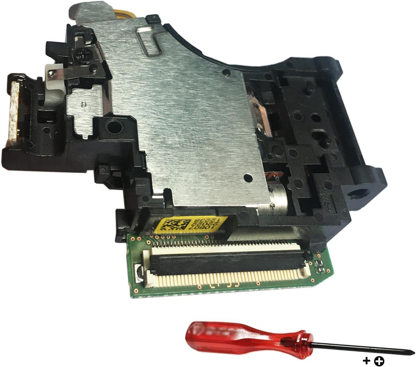
– Grip the edges of the optical drive cable connector with your fingers and give it a gentle tug upwards to detach it from the motherboard. You’re doing great!
Step 20


– Grab the edges of the optical drive cable connector with your fingers, and lift up to unplug it from the optical drive.
Step 21
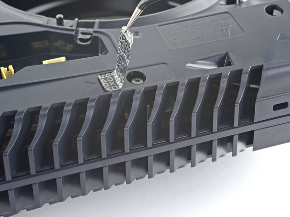

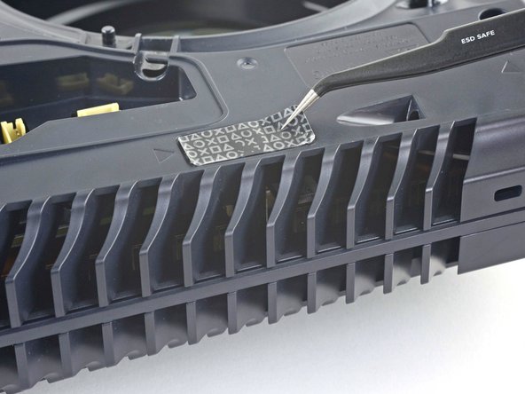
If your PlayStation 5 is still in its unopened glory, that sticker will be pure black. Once you peel it off, you’ll see the hidden pattern come to life.
Now, these are technically tamper-evident stickers, but no need to sweat it—Sony can’t legally void your warranty as long as you keep everything intact. Enjoy the journey!
– Grab a trusty pair of tweezers and gently peel away that tamper-evident sticker hiding the last screw of the case. You’ve got this!
Tools Used
Step 22

– Grab your trusty T8 Torx driver and let’s tackle those eleven screws holding the case together:
– Six screws that are 18.6 mm long – they’re like the little guys holding it all down.
– Two screws measuring 23.3 mm long – the middleweights, doing their part.
– Two beefier screws at 43.2 mm long – the heavy hitters in this repair.
– And don’t forget the lone hero, a 7.3 mm long screw, ready to save the day!
Step 23


– Lift the case up and away to remove it.
Step 24


Grab the pull tab, not the cable! If you need help, you can always schedule a repair.
– Grab your trusty spudger and gently press down on that metal locking tab for the optical drive connector. You’ve got this!
– With the tab nicely pressed down, take a pair of tweezers and give the blue pull tab a gentle tug straight out from the connector. This will disconnect that cable from the optical drive like a pro!


Step 26


– Grab your trusty spudger and use the flat end to gently press down on that shiny metal locking tab of the optical drive connector.
– Now that the tab is feeling the love, take a pair of tweezers and give that blue pull tab a nice, steady tug straight out from the connector to disconnect the cable from the motherboard. You’ve got this!
Step 27


– Grab a pair of tweezers and gently coax that blue pull tab in the opposite direction from the connector. This will help you free up the power and eject button ribbon cable. You’re doing great, keep it up!
Tools Used
Step 28


– Grab a pair of tweezers and gently pull the cool blue tab directly away from the connector to disconnect the LED ribbon cable.
Tools Used
Step 29


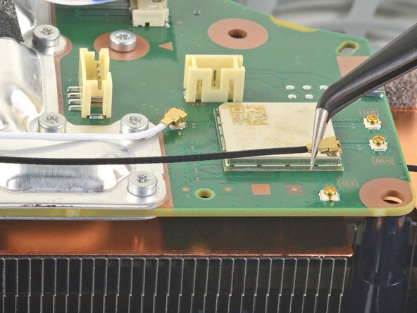
Some board versions might be missing these antenna wires. If you find your board doesn’t have these connectors, just breeze on past this step!
– Use tweezers to firmly grip the white Wi-Fi antenna wire at its metal base, close to the connector.
– Lift the connector straight up to disconnect it from the motherboard.
– Repeat this for the black Wi-Fi antenna wire.
Tools Used
Step 30


– Grab a pair of trusty tweezers and carefully hold on to the black or blue power supply antenna wire from its metal base, making sure to get as close to the connector as you can.
– Give that connector a gentle lift straight up to say goodbye to its connection with the motherboard.
– Repeat the same friendly disconnection dance with the white power supply antenna wire.
Tools Used


Step 32


– Follow the same procedure to lift off the four remaining stickers.
Step 33


– Grab a trusty pair of tweezers and gently lift that white sticker that’s keeping the LED ribbon cable cozy against the heat sink.
– Carefully slide the LED ribbon cable out from beneath the sticker—it’s time for it to breathe!
– Once you’re done, just press that white sticker back onto the heat sink so it can keep doing its thing for next time.
Tools Used
Step 34

– Alright, grab your trusty T8 Torx driver and get ready to say goodbye to forty-two pesky screws that are holding down the top shield plate!
– You’ll find forty-one screws that are 7.3 mm-long and one longer screw measuring at 43.2 mm.
Step 35


Make sure the replacement pads are the same thickness as the originals; otherwise, the foam around the APU might not seal up just right.
– Pop off the top shield plate from the motherboard to get it out of the way.
– When putting it back together, this is a great moment to swap out any thermal pads on the main board if needed. The pads might be stuck to both the top shield plate and the main board. If you need help, you can always schedule a repair.
Step 36


– Gently press down on the metal locking tab on the USB board cable’s connector—think of it as giving it a little hug.
– With that tab held down, grab your trusty spudger and place its flat end against the insulating foam pad on the ribbon cable. Now, pull it straight out from the connector to disconnect it. Easy-peasy!
Tools Used
Step 37

Keep your eyes peeled for that tiny spacer hiding under the screw. It’s a little sneaky!
When you’re tackling those screws, don’t go solo! Removing or installing one at a time could put your APU at risk. Instead, take a chill approach: alternate between the two screws, giving each a gentle half turn at a time. This way, you’ll keep that bracket snug without any drama!
– Grab your trusty Phillips screwdriver and let’s tackle that 11 mm-long SSD screw. It’s time to set it free!
– Next up, take that same Phillips screwdriver and go after those two 11.8 mm-long APU tension bracket screws. They won’t know what hit them!
– Lastly, switch it up with a TR8 Torx security screwdriver and remove the two remaining 7.3 mm-long main board screws. You’ve got this!
Tools Used

Step 38
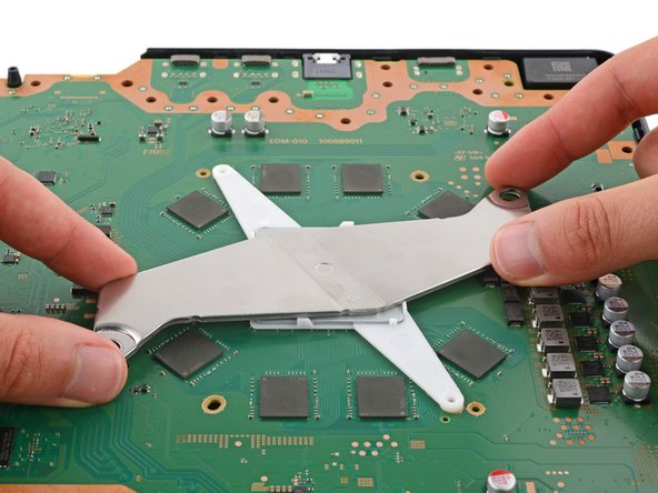
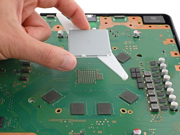
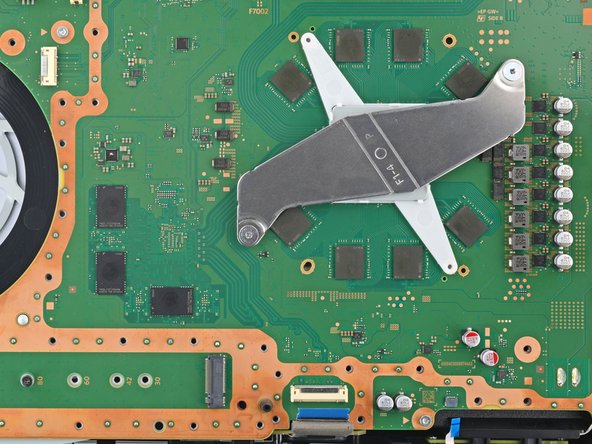
– Gently lift and take off both APU brackets from the board.
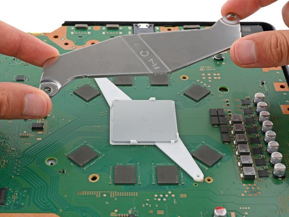
– Now, as you get ready to put things back together:
– Start with the bracket that has the plastic arms so the pegs fit nicely into their designated cutouts.
– Next up, place the metal bracket on top of the plastic one, making sure they’re at right angles and the screw holes match up perfectly.
Step 39
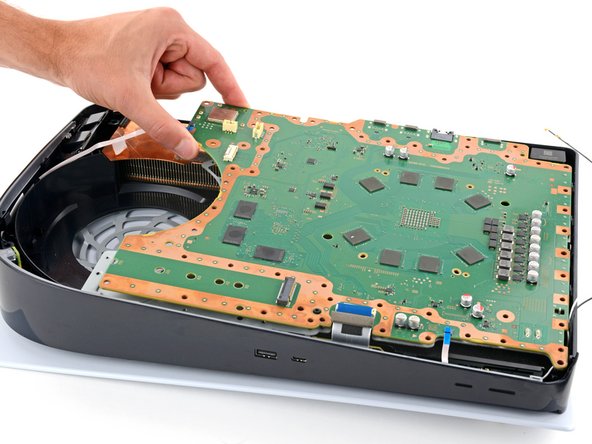

Hey there, just a heads-up – avoid yanking out the motherboard completely just yet! The little corner by the power button is still holding on tight with those sneaky metal prongs. We’ll set it free in the next step.
The small thermal pads that connect the main board to the metal shield plate below might make it tough to separate the board. If your PlayStation is older or those pads are stubborn, you might need to flex those muscles a bit! If you need help, you can always schedule a repair.
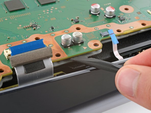
– Carefully lift the edge of the motherboard featuring the large cutout to start pulling it away from the bottom shield plate.
– With the board elevated, slide the flat end of a spudger between the board and the bottom shield plate, giving it a gentle twist to help them part ways. Continue this around the entire perimeter of the board.
Tools Used
Step 40


The power supply connects to the lower part of the main board assembly with some nifty metal prongs snugly fitting into the bottom left corner.
You should feel those prongs slide right out like they’re ready for a little break!
– Gently slide the flat end of a spudger between the board and the lower shield plate, right by those two parallel solder joints near the corner where the power button is chilling.
– Give the spudger a little twist to pop those two prongs under the board out of their cozy socket.
– When it’s time to put everything back together, press down on the corner of the board to snugly fit the prongs into the power supply—you’ll feel them click right into place!
Tools Used
Step 41


Be gentle with the board and avoid pressing it against your workspace; we want to keep those delicate components safe and sound!
– Gently detach the main board, give it a little flip, and lay it down on a tidy work surface with the APU peeking up at you.
– As you put everything back together:
– Ensure all cables connecting to the board are neatly tucked away so they don’t end up trapped below.
– Carefully turn the board over so the APU is now on the bottom, being cautious not to let any liquid metal escape.
– Keep the board nice and level as you lower it back into position.
Step 42

Don’t forget to put on those awesome gloves to shield your hands from the liquid metal.
Handling the liquid metal is a bit of a game—it’s slippery and spreads around. Grab some fresh cotton swabs and keep the alcohol coming as needed.
For the new liquid metal to do its magic, the surface needs to be spotless. If you need help, you can always schedule a repair.
– Got a disposable syringe lying around? Perfect! Use it to suck up any big puddles of liquid metal. Just don’t mix up your old and new liquid metal syringes.
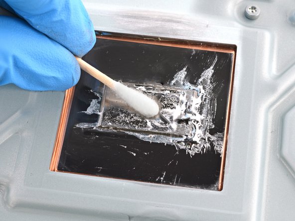
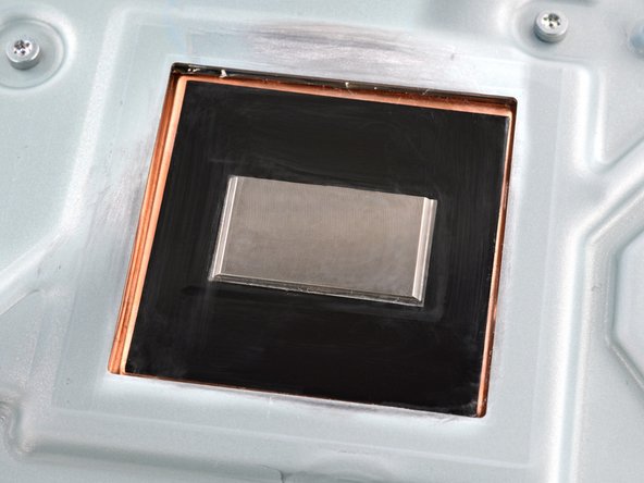
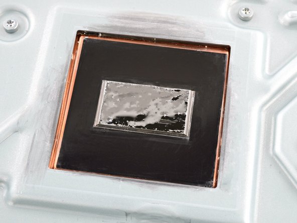
– Now, let’s tackle that heatsink: squeeze a few drops of super concentrated (over 90%) isopropyl alcohol onto a cotton swab. Gently wipe away all the liquid metal from the heatsink surface.
– Repeat this cleaning process to make sure all the liquid metal residue is gone.
– Give the heatsink some time to air dry completely.
Tools Used


Step 43


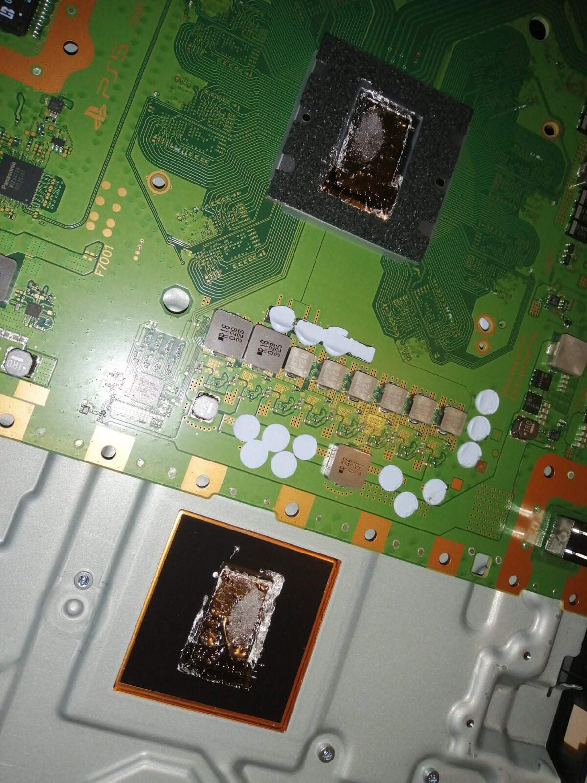
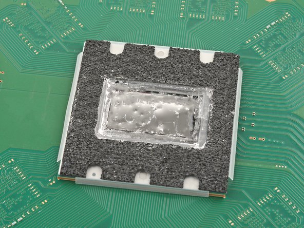
Keep that liquid metal away from the board! It’s like a misbehaving toddler—super conductive and prone to causing chaos. The foam barrier is your trusty sidekick, keeping everything neatly contained.
Double-check that your replacement pads match the original thickness. If they’re not on the same page, the foam around the APU might not seal up as it should. Let’s keep it snug!
Keep that foam barrier snug around the APU! It’s doing a great job protecting everything.
– Just like you did with the heatsink, take a moment to clean off all that old liquid metal and its pesky residue from the APU. It’s like spring cleaning for your device!
– Now’s a great time to swap out any thermal pads on the bottom of the main board if they’re looking worse for wear. Sometimes, those pads can be a bit clingy, so be gentle as you separate them from both the bottom shield plate and the main board.
Step 44

When your liquid metal syringe comes with multiple tips, go for the one with the tiny needle-like head.
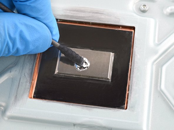
– Squeeze a tiny dab of liquid metal onto the heatsink (let’s skip the APU for now)—roughly the size of a small matchstick head will do the trick.
– Grab the spreader that came with your liquid metal or a fresh cotton swab, and gently press down to spread the liquid metal evenly across the entire surface. You’re doing great!
– If you spot any extra liquid metal hanging around, just use the syringe to suck it back up and keep things tidy.
Step 45

Your cotton swab from the previous task should still have some liquid metal residue on it.
The main board is now all set for reassembly.
– To give your APU some love, use the trusty cotton swab to spread a smooth layer of liquid metal across its surface. If you find your APU craving more metallic goodness, gently tap the swab on the heatsink to borrow some, or simply squeeze a tiny droplet from the syringe.