
How to Fix an iPhone 11 Pro That Won’t Turn On
Duration: 45 minutes
Steps: 12 Steps
Step 1


- Unscrew the two pentalobe screws at the bottom edge and gently lift the screen up.
- Once the screen is up, carefully remove the shielding covers, disconnect the battery, and take out the screen.
Step 2


This means the hefty current isn't playing nice with the other flex cables; the real troublemaker is on the motherboard! No worries, we've got this.
Since the circuit is multitasking and powering both the logic board and signal board, we’ll need to pop off the motherboard to sniff out the issue.
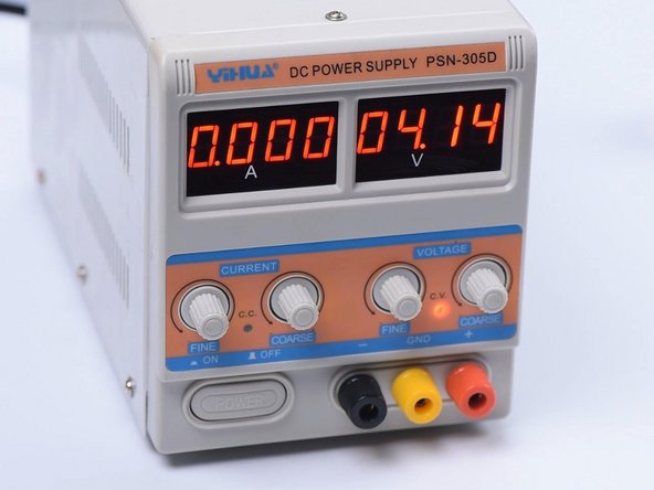
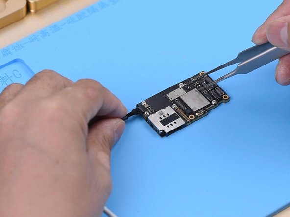
- Start by connecting the motherboard to the Power Cable. The ammeter is showing a hefty 3.1A current. That's a lot of juice!
- Next, detach the motherboard and reconnect it to the Power Cable. The ammeter is still reading a solid 3.1A current. Looks like the power's flowing just fine!
- Now, let's take a look at pin 1 on the J7010 of the battery connector in diode mode. The reading is 0, which tells us that the main power supply circuit is shorted to the ground. Time for a closer inspection!
Step 3

- Carefully peel off the foam from the motherboard.
- Next, warm up the back of the motherboard using a Hot Air Gun set to 240℃ to gently lift off the shielding paper.
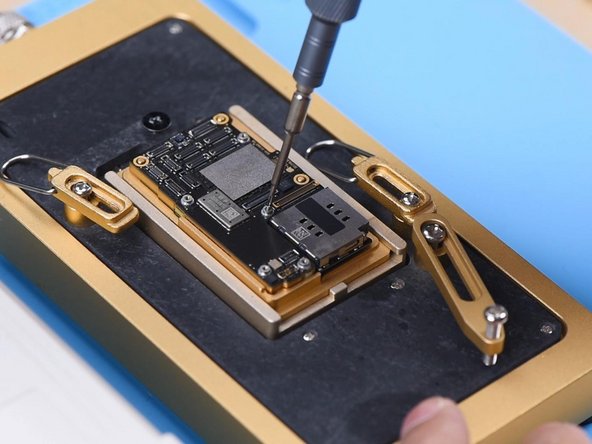
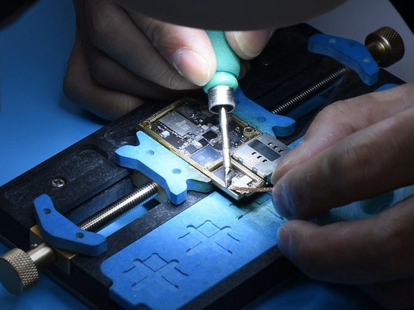
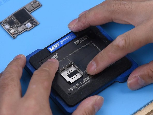
- Place the motherboard onto the Heating Platform. To make prying the logic board easier after separation, screw in a screw on the logic board.
Step 4


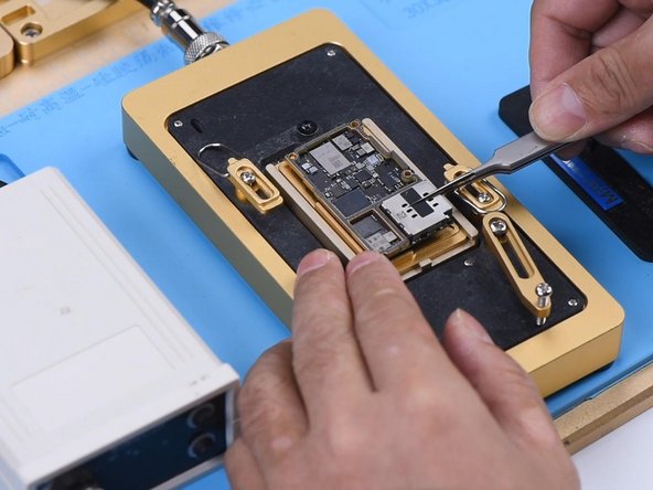
- Set the heating platform to 185℃ and let it warm up. Give it a few moments, it'll be ready to go in no time.
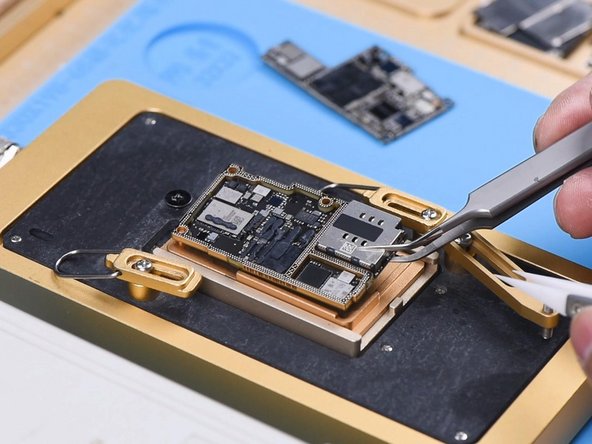
- Once the temperature hits 185℃, it's time to clamp the screw and carefully remove the logic board. After that, gently remove the signal board.
Step 5


- Test pin 286 on the signal board in diode mode. If you get a 0, it means the signal board's main power supply is grounded – something's shorted out.
- Now, check pin 286 on the logic board. A reading of 363 means everything's running smoothly with the logic board. Nice and normal.
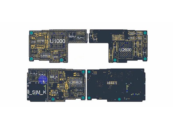
- Open up the bitmap. You’ll see a bunch of components tied to the main power supply circuit. It's a busy little area in there.
Step 6
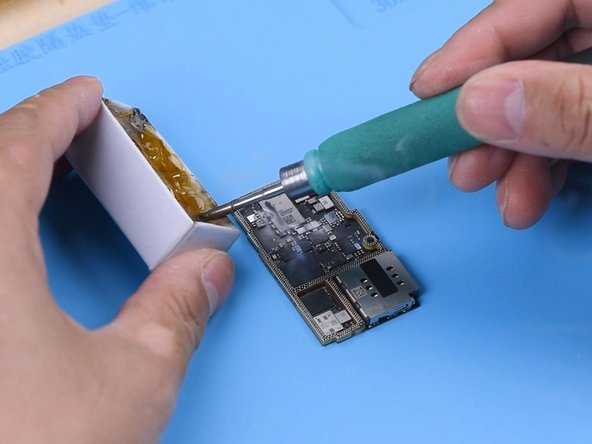
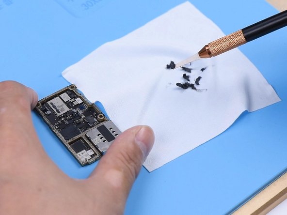
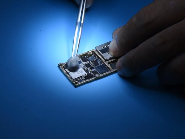
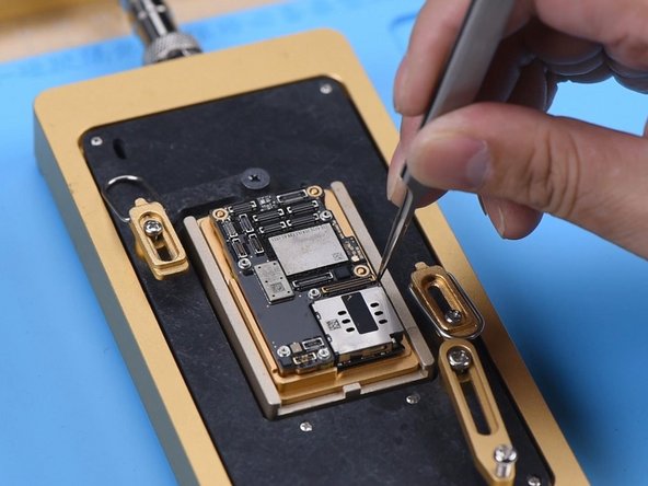
- Time to track down that troublemaker component! Grab your Sculpture Knife and remove the thermal grease—think of it as giving your board a fresh start.
- Now, dip your Soldering Iron in rosin (set to 365℃), and waft some rosin smoke over the signal board. It’s like a spa day for electronics!
Step 7
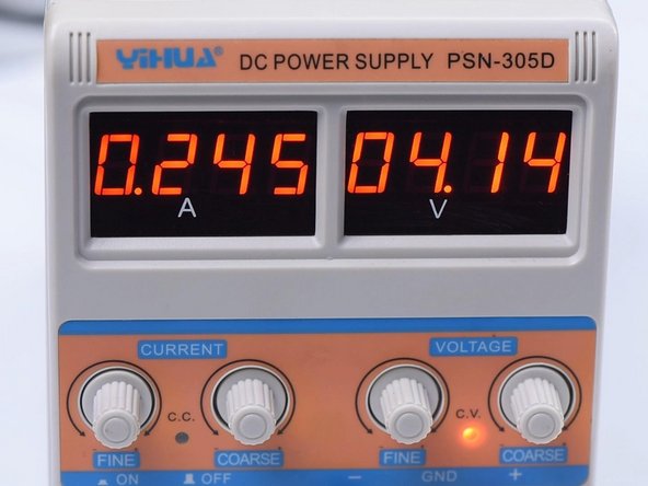
- Dial your direct current supply up to 4.1V. Grab your multimeter probes and connect them—positive to positive, negative to negative. Hook up the black probe to ground, and the red one to pin 286 on the signal board.
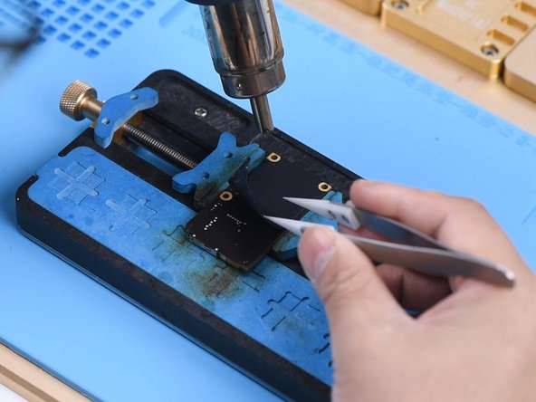
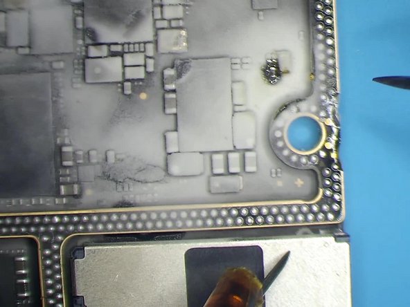
- Spot some melted rosin on C1200_K? That’s our clue: this capacitor’s had a rough day and needs replacing.
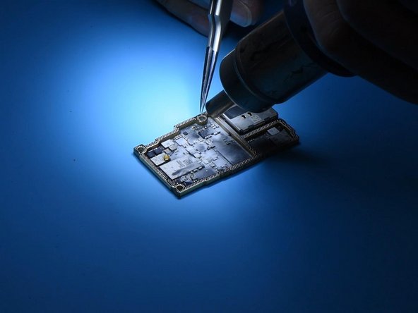
- Fire up your Hot Air Gun to 350℃, aim it at the wounded capacitor, and use tweezers to whisk it away. Like a pro!
Step 8
- Give that signal board a quick spa day with some PCB Cleaner to wipe away the rosin.
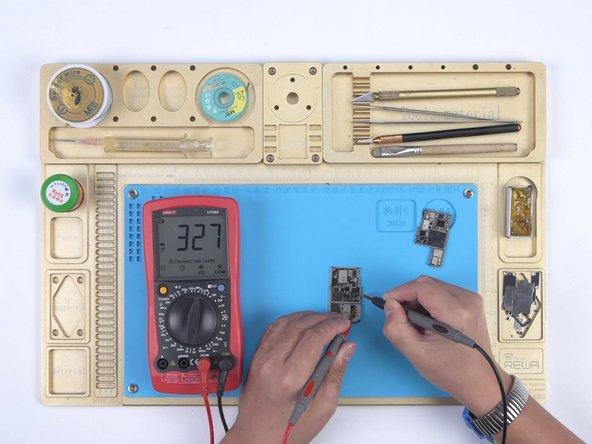
- Fire up diode mode for round two. You’re looking for a solid value of 327—nice and normal.
- Grab your soldering iron, set it to 365℃, and team it up with some solder wick. Glide over the bonding pad to clear away any leftover tin.
Step 9


- Give the signal board a nice clean with some PCB Cleaner. Go ahead and remove any tin, then clean the logic board the same way.
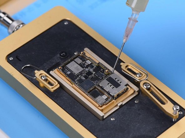
- Now, attach the signal board to the Reballing Platform and position the Reballing Stencil. To keep the solder paste from sneaking into the motherboard crevices, add a metal plate for protection.
- Apply a smooth layer of low-temperature Solder Paste.
Step 10

- Lift off the Reballing Stencil and set the signal board onto the Heating Platform at 185℃. Let it bask in the warmth for a bit.
- Once those solder balls have strutted their stuff, power down and let the motherboard chill out for 5 minutes.
Step 11
- Spread a bit of Paste Flux, then line up the logic board with the signal board. Chill out while you heat things up on the Heating Platform at 185℃.
- Once you hit that magic 185℃, let the boards soak in the heat for a solid minute so they stick together nice and snug.
Step 12
- Hook up the motherboard using the Power Cable, then give pin 12 on J7700 a quick ground short. Watch the boot current settle down to normal.
- Place the motherboard back into the phone and reconnect the flex cables, screen, and battery. Since the battery is dead, plug in the charger and the phone should power on without a hitch.


