How to Remove the Mainboard from Huawei P8 Lite Guide
Duration: 45 min.
Steps: 15 Steps
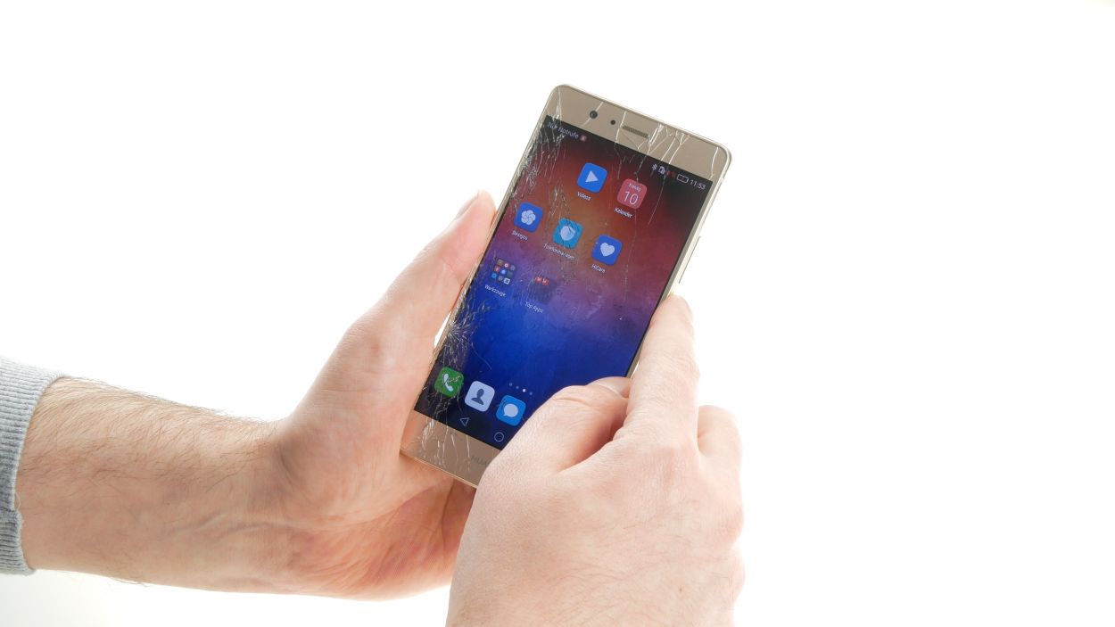
In this guide, we’ll walk you through the process of removing the motherboard from your Huawei P8 Lite all by yourself! If your device has had a little too much fun in the water, taking out the PCB is a must for a thorough cleaning. Remember, if you need help, you can always schedule a repair!
Step 2
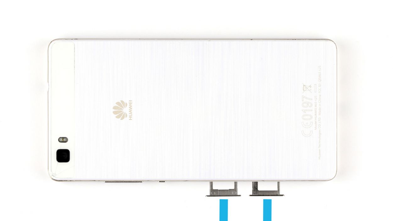
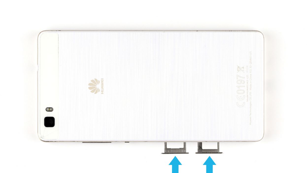
– Pop out the two trays for the SIM and microSD cards from the device by gently pushing a SIM Tool or a paperclip into the tiny hole until the tray slides out. Once you’ve got them out, go ahead and remove both trays along with the cards. Easy peasy!
Step 3
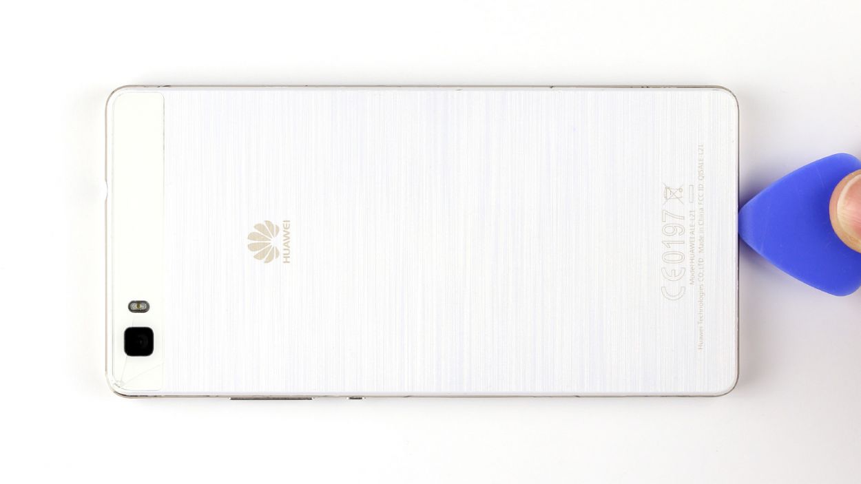
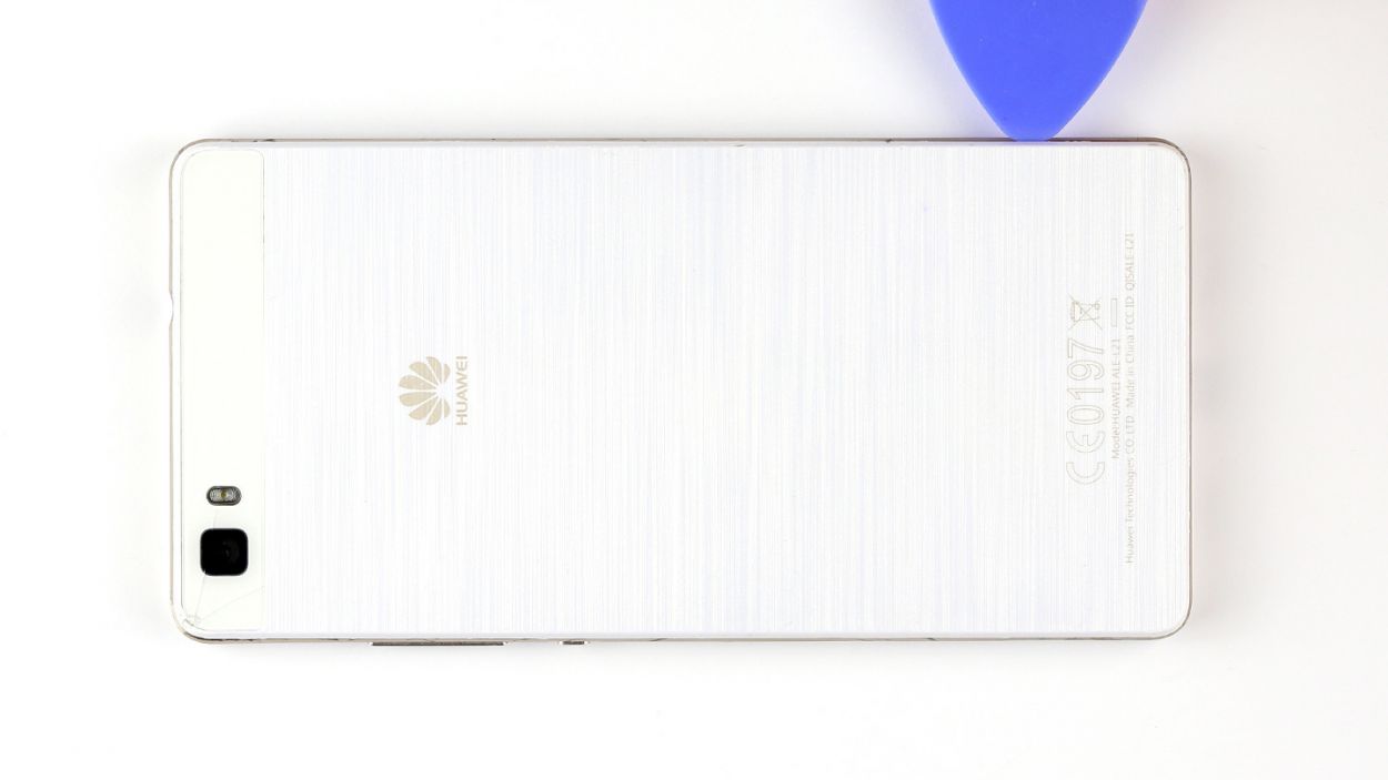
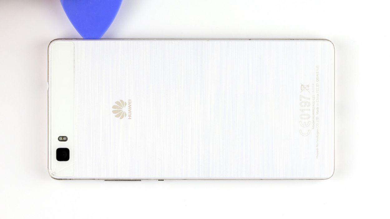
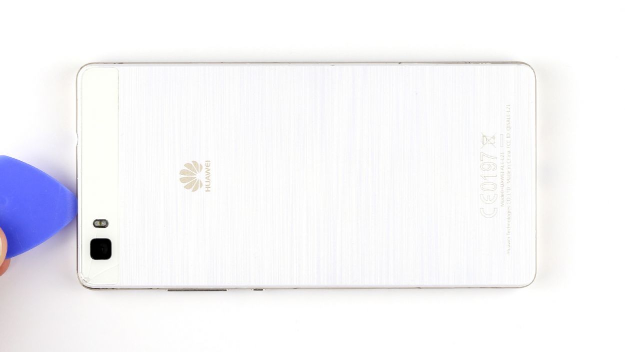
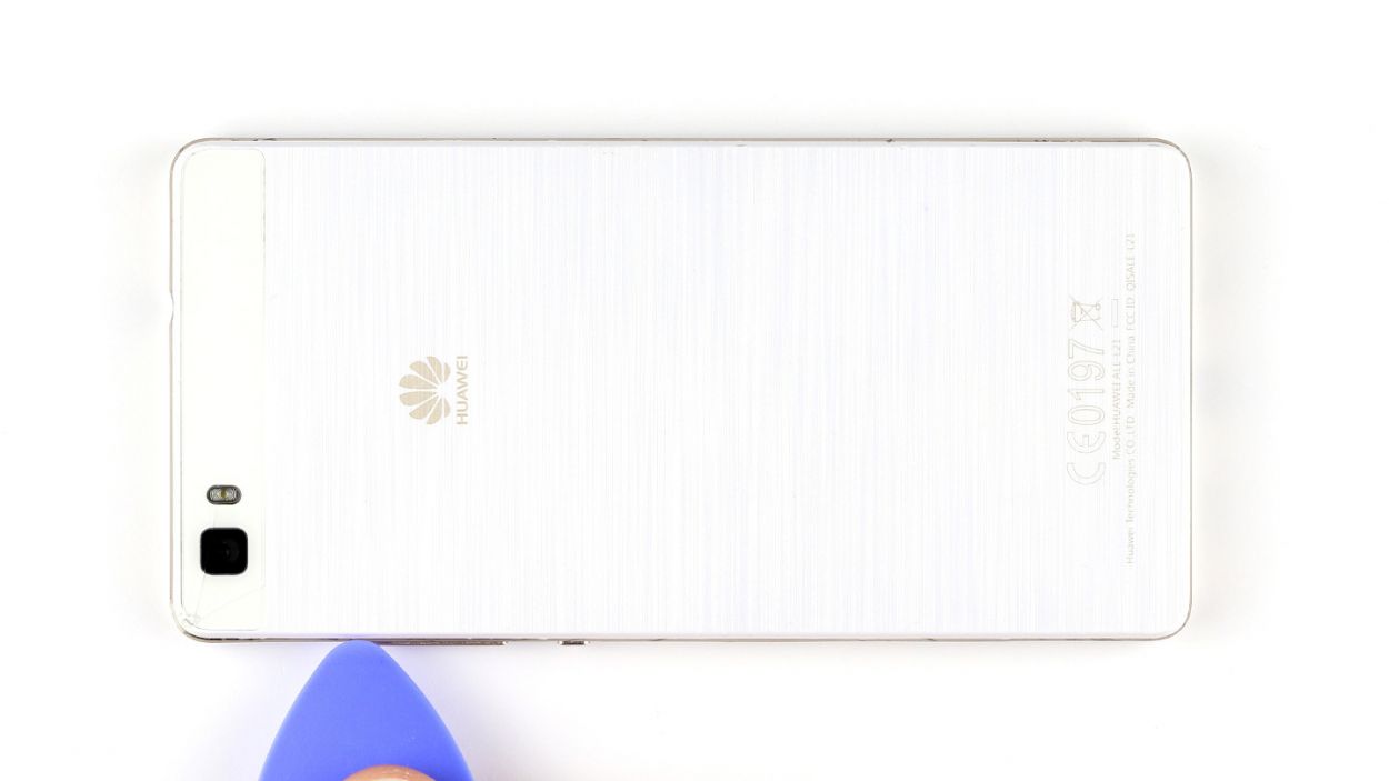
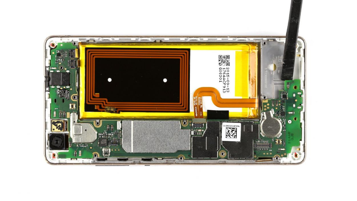
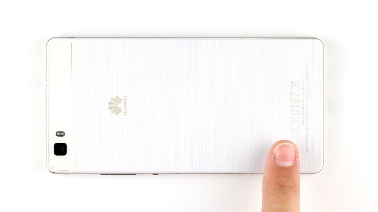
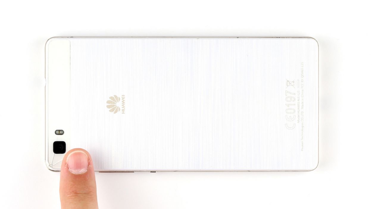
– Time to get started! Carefully pry the back cover away from the enclosure frame. You’ll see it’s hooked on at several points, so gently work a pick between the cover and the frame to release the hooks. Repeat this process all the way around your device.
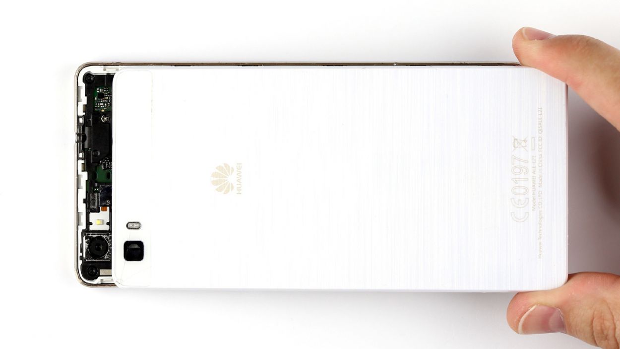
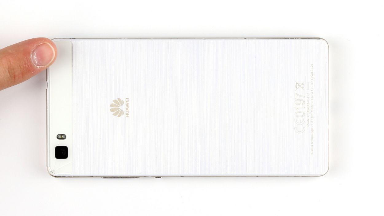
– Now it’s time to remove the back cover. Take a deep breath and carefully lift it off. You got this!
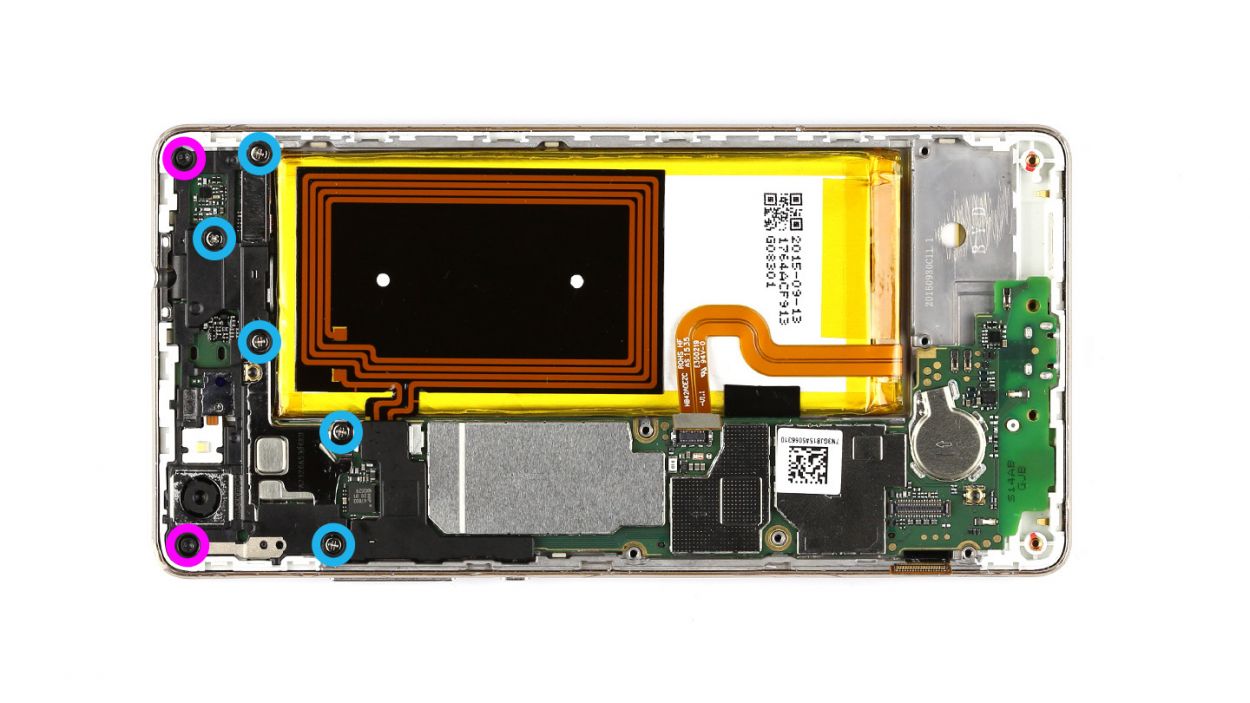
Step 4

– Time to tackle that pesky speaker! Start by unscrewing the seven screws that are keeping it cozy in there: you’ll need 3 of those 2.7 mm PH00 Phillips screws and 4 of the 3.7 mm T5 Torx screws. Grab your screwdriver and show them who’s boss!
– Once those screws are out, gently lift the speaker out of your device. You’re doing great!
Step 5

– Time to get your screwdriver out! First up, let’s take out those three screws—3 x 2.7 mm PH00 Phillips screws, to be precise.
– Next, gently lift off the silver cover from your device. It’s like peeling an orange, but way cooler!
– Now, with a little finesse, disconnect the battery contact from the PCB. Slide your tool underneath the contact and give it a gentle lift. Just be careful not to break anything on the board—it’s a delicate dance!
– Finally, do the same for the display contact. You’ve got this!
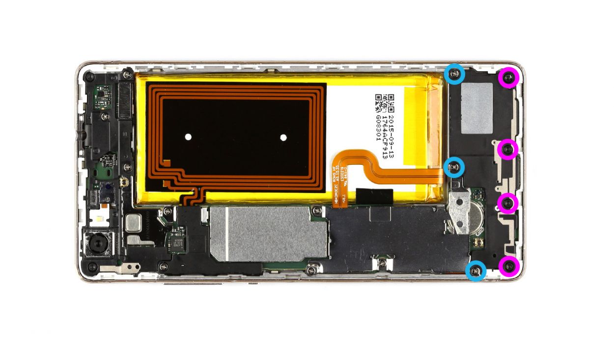
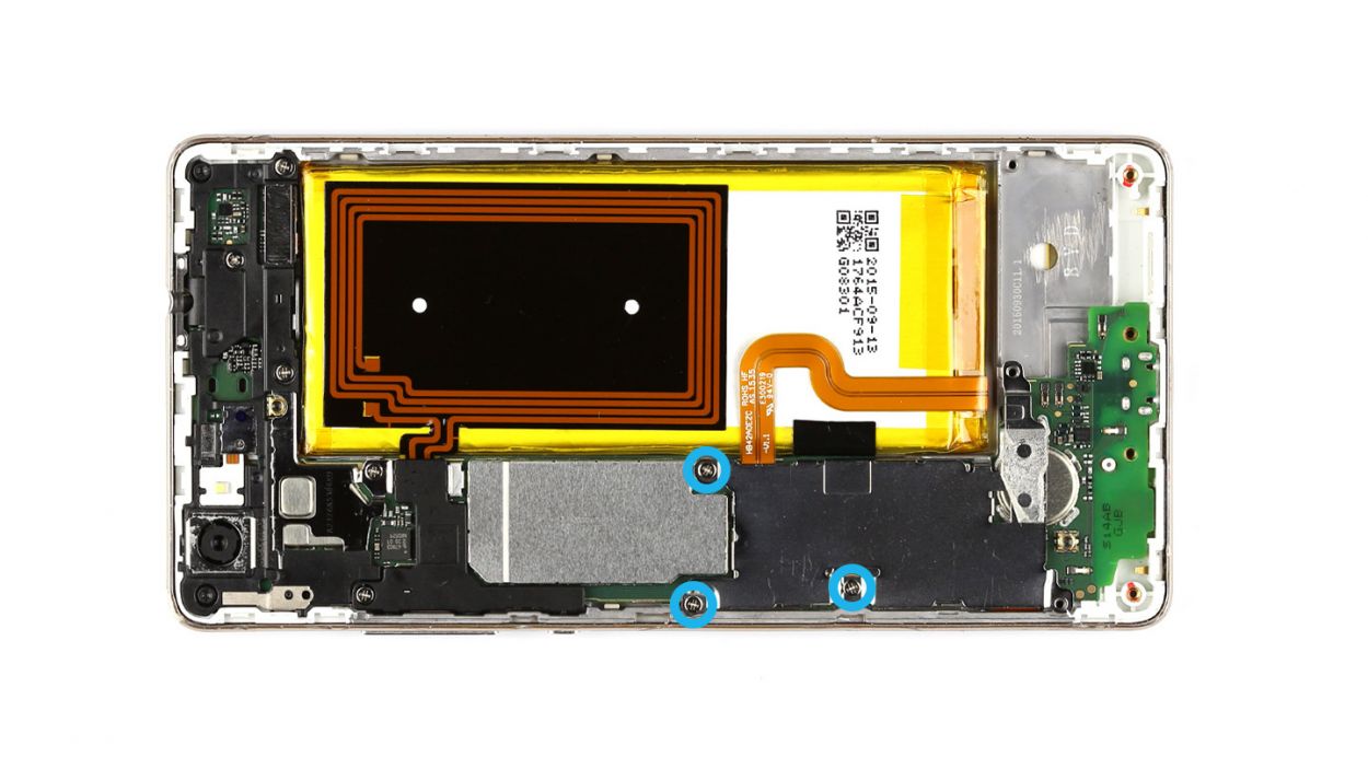
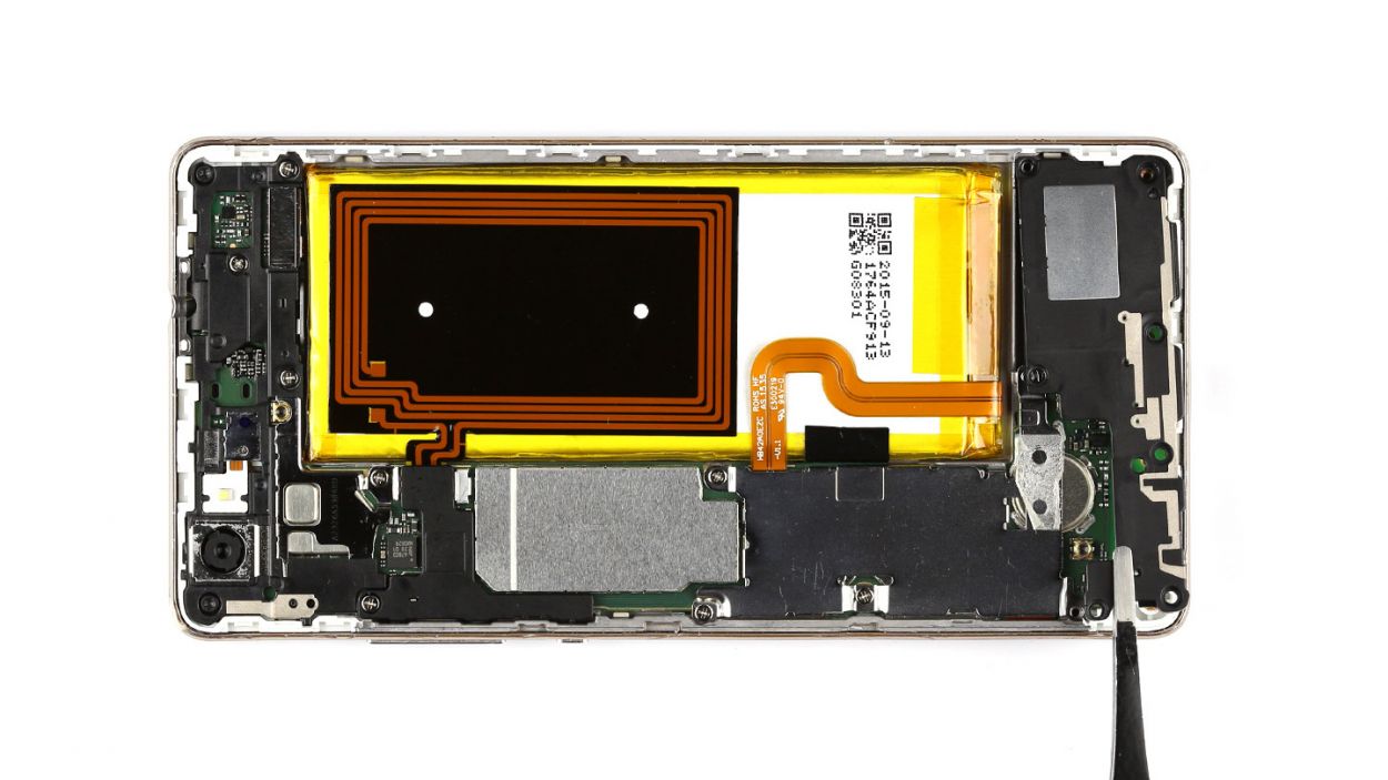
Step 6


– Start by taking out those seven screws holding the cover on. You’ll need 5 x 2.7 mm PH00 Phillips screws and 2 x 3.7 mm T5 Torx screws for this job.
– The cover is made up of two parts, so let’s gently lift off the larger upper cover using a trusty pair of tweezers.
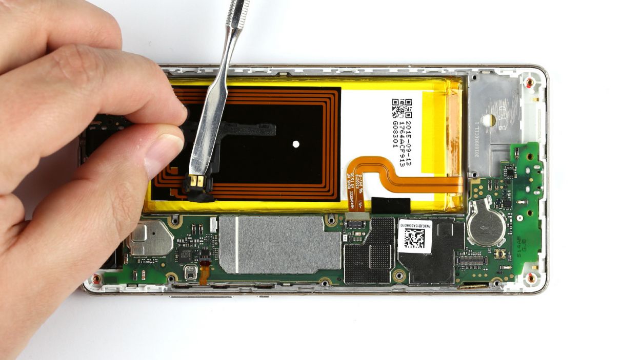
– Now, the NFC antenna’s contact is glued to the bottom of the smaller cover. Flip that cover over so you can disconnect the contact.
– Carefully pry apart the contact by sliding a steel laboratory spatula between the contact and the cover. Easy does it!
– Don’t forget to remove the little cover as well!
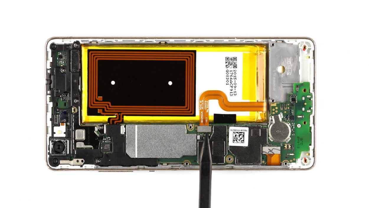
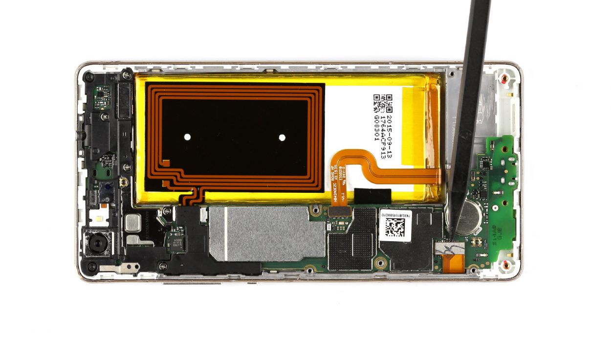
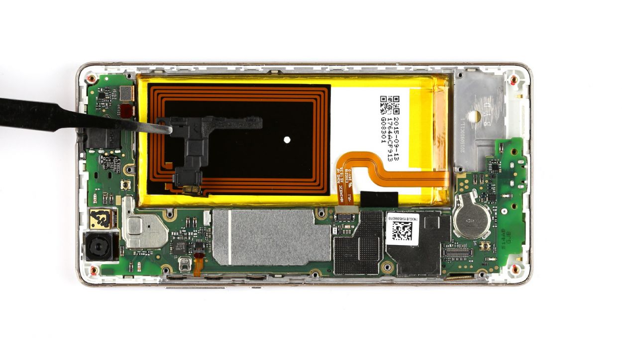
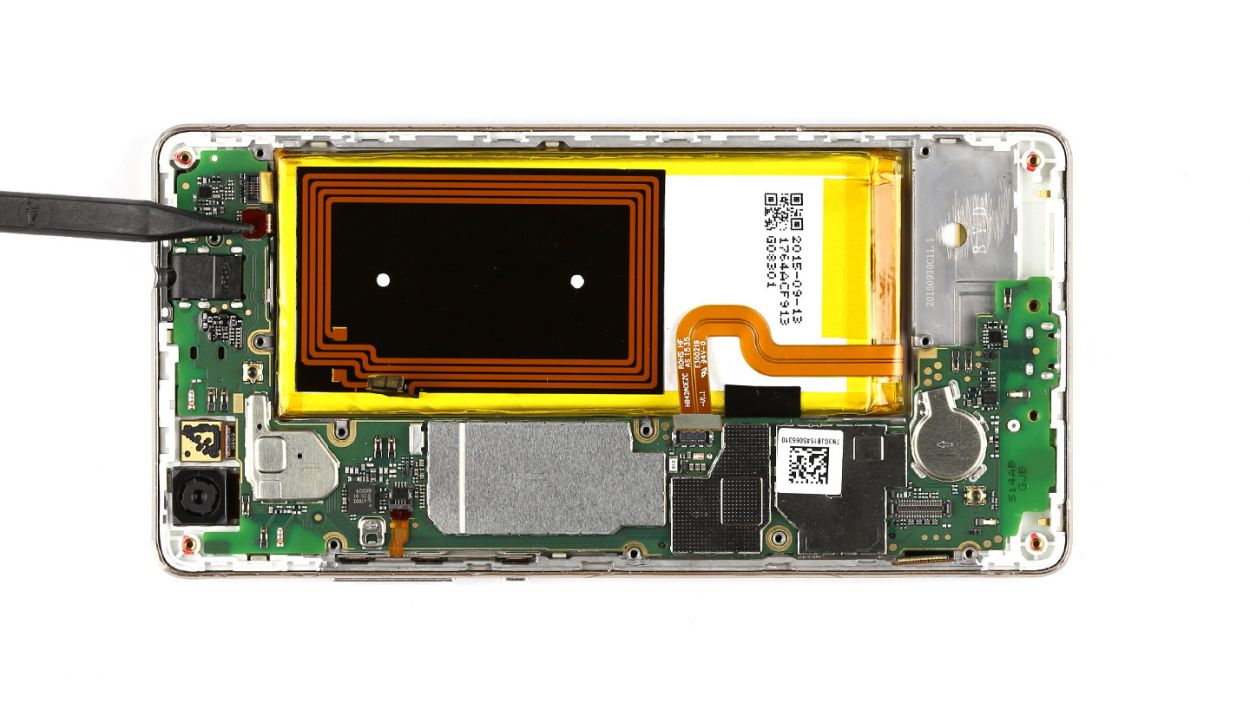
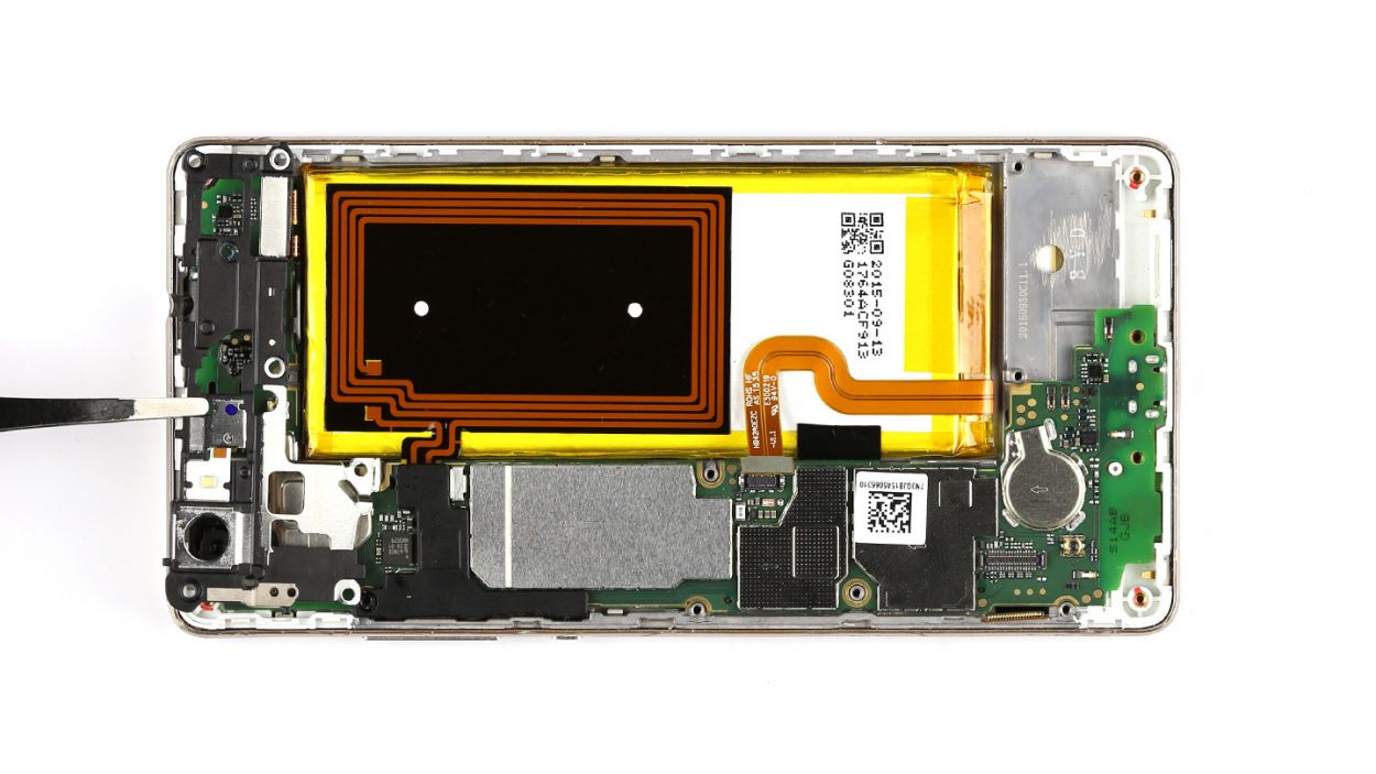
Step 7


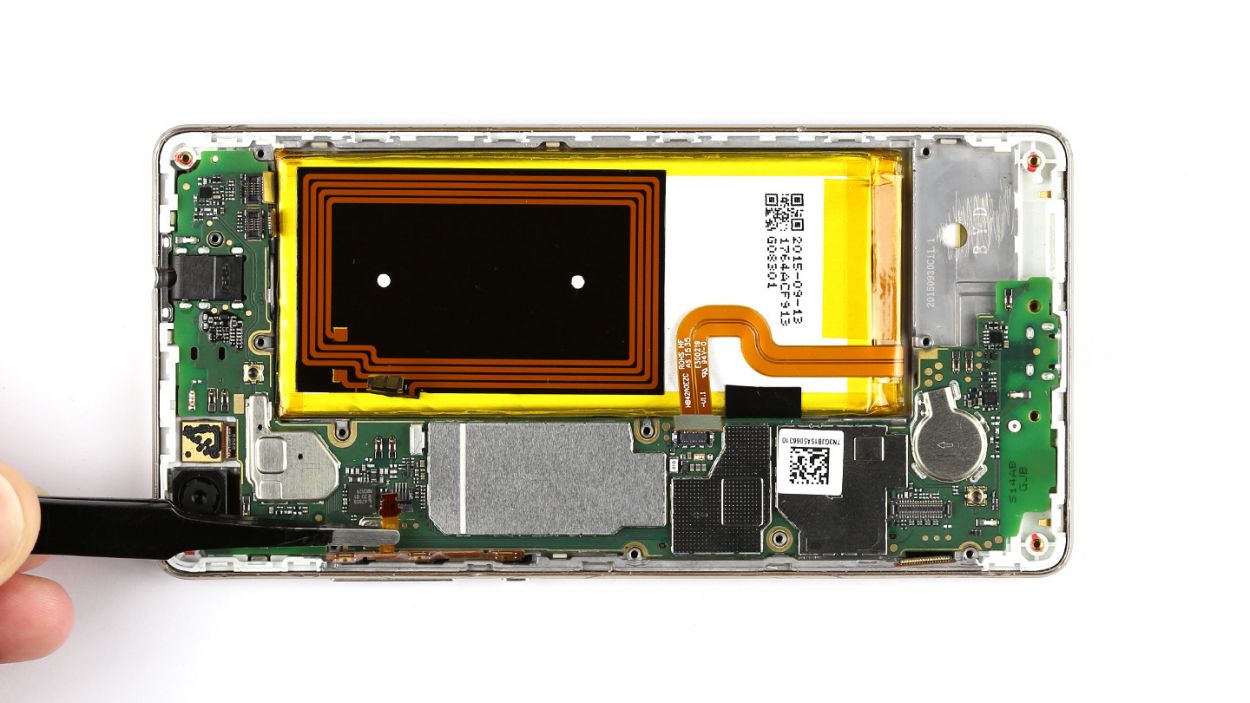
– First things first, let’s disconnect that touchscreen contact from the motherboard. Just slide your tool underneath and give it a gentle lift!
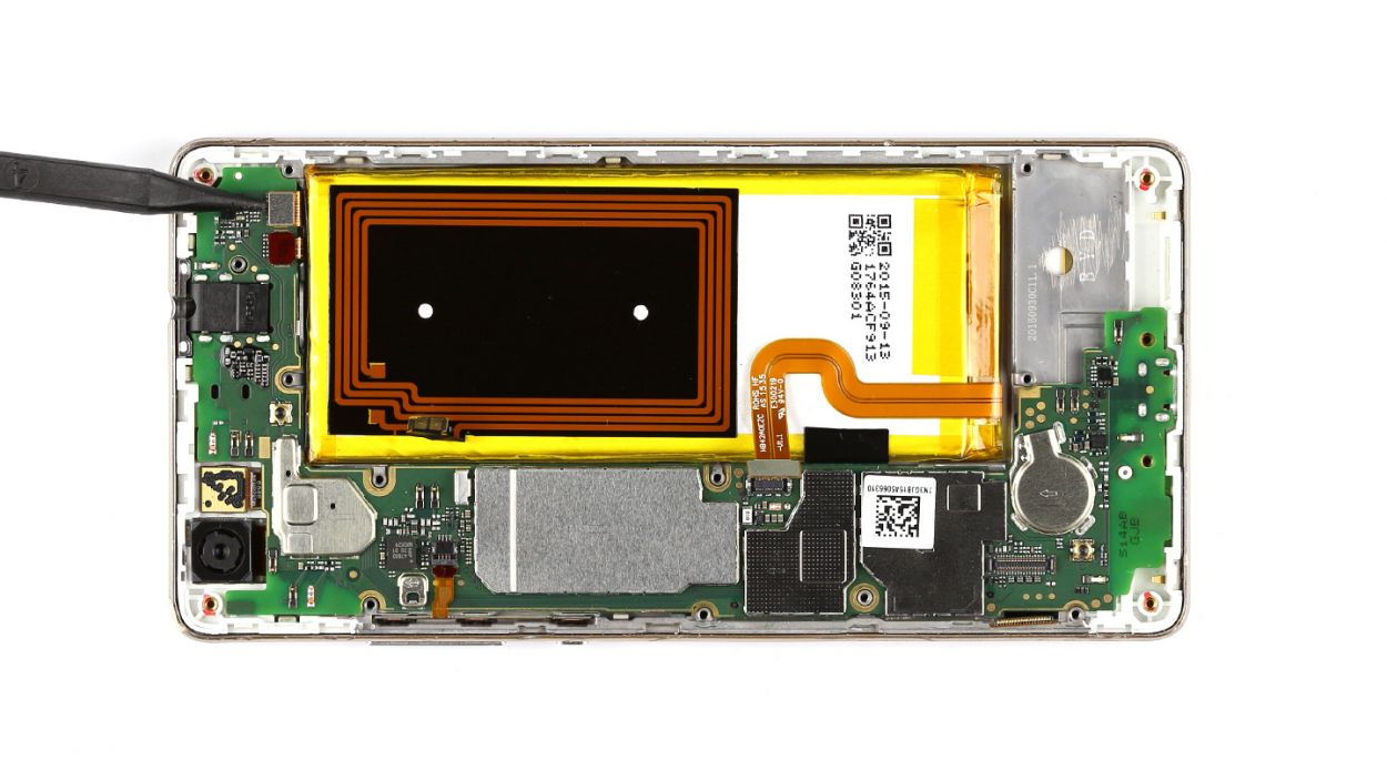
– Next up, it’s time to tackle the sensor cable. Just like before, slide it under and lift it off with care.
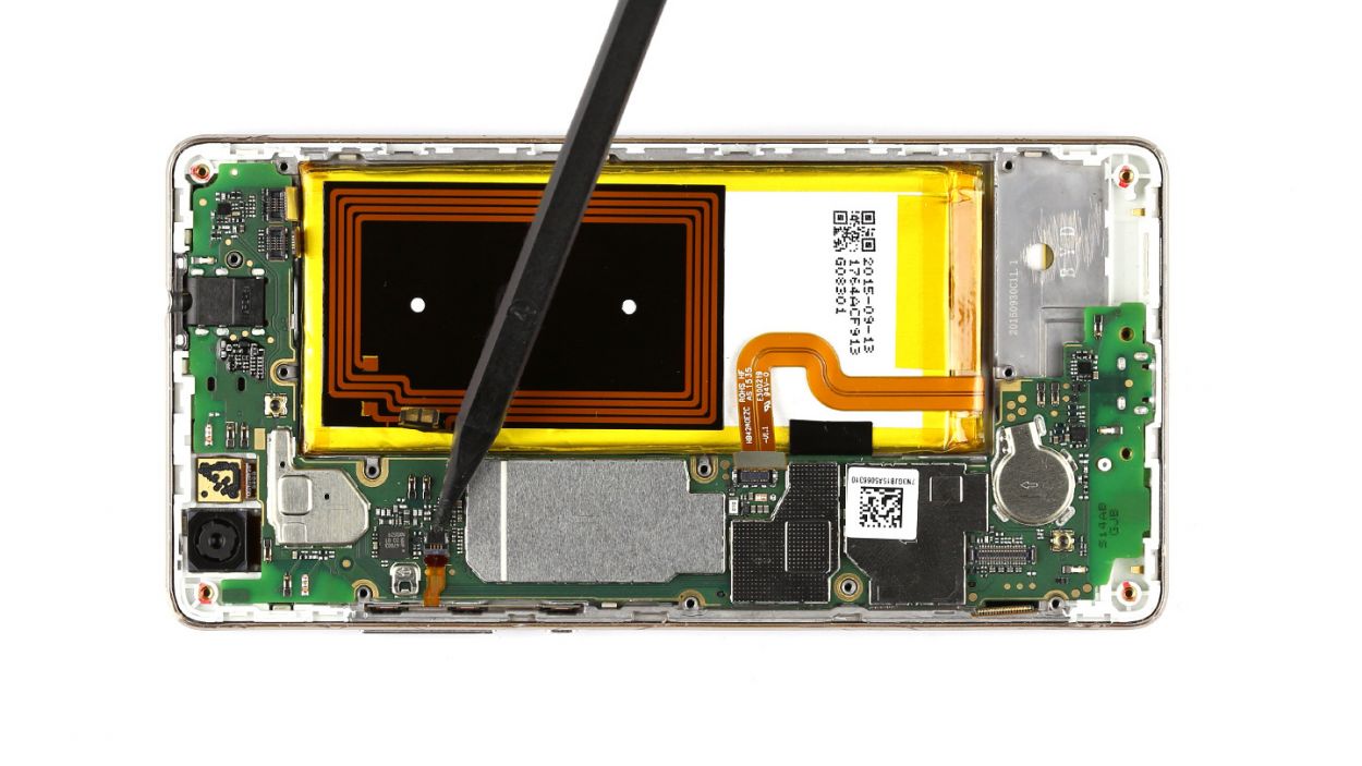
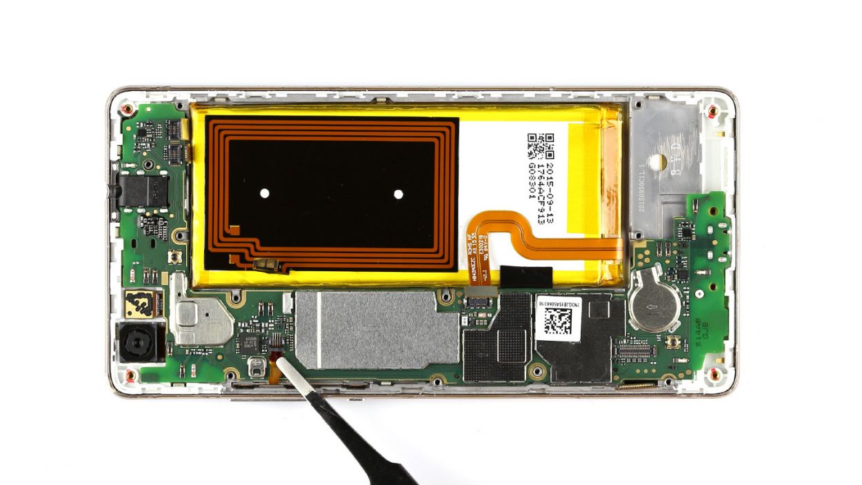
– Now, the control button contact is held in place by a tiny bracket. Lift that bracket to free the contact and gently pull out the cable. Remember, be kind to the cable—no yanking or bending too much!
– Finally, it’s time to remove those control buttons from the device. You’ve got this!
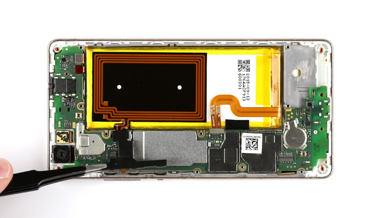
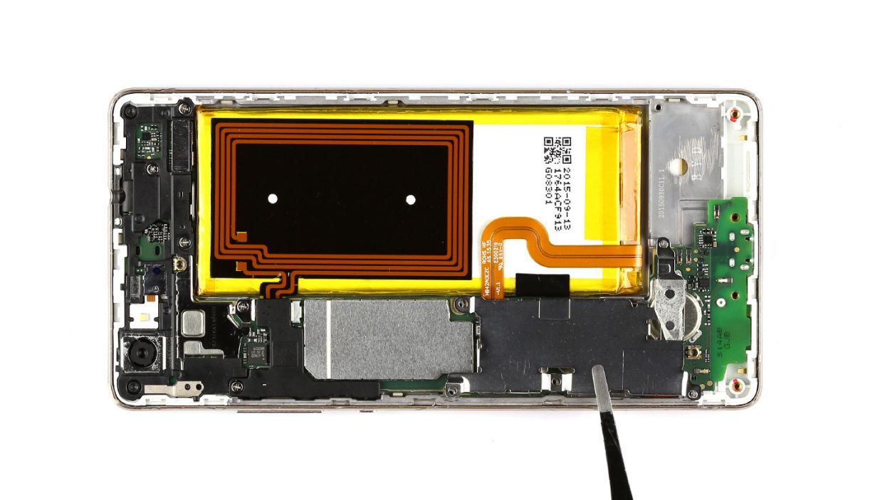
Step 8
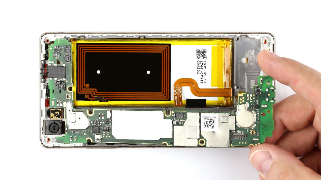
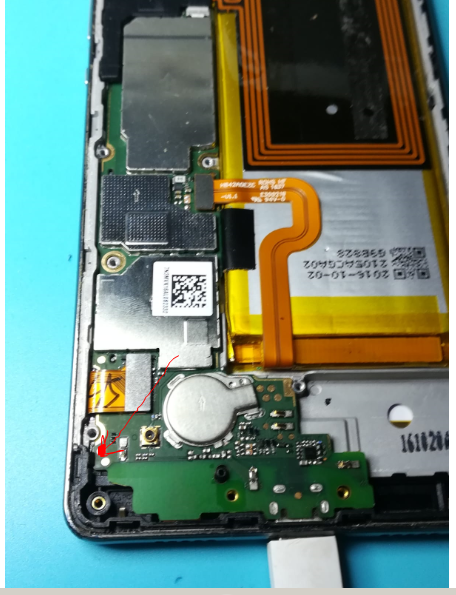
– Gently lift the PCB out of your device. Slide a spudger or a similar tool underneath the board and give it a little nudge upwards.
– Carefully hold the PCB between your thumb and finger, and then take it out with a smooth motion.
Step 9

– Slide that PCB into the enclosure like a pro! Just make sure it’s snug and in the right spot. Start by inserting the PCB at the top of the device so you can easily guide the headphone jack through the frame’s opening. You’ve got this!
Step 10


– Pop those control buttons back in and make sure they’re snug with the motherboard.
– Slide that cable right back into its cozy socket and secure it with the bracket.
– Gently press the connector into the socket to link up those sensors with the board.
– Repeat the same smooth move for the touchscreen connector.
Step 11


– Flip that smaller cover upside down and place it on the battery so you can reconnect the NFC antenna’s contact. Easy peasy!
– Carefully place the antenna contact back into its cozy spot on the cover. Give it a good press to make sure it sticks tight.
– Align the cover just right on the motherboard, like a puzzle piece finding its home.
– Now, let’s get that larger cover back on! Ensure that the little cover and the big cover are snugly hooked together.
– Grab those seven screws and secure the covers to the enclosure. You’ll need 5 x 2.7 mm PH00 Phillips screws and 2 x 3.7 mm T5 Torx screws. You’ve got this!
Step 12


– Gently connect the PCB to the display by pressing the display contact into the socket on the PCB until you hear that satisfying click.
– Now, let’s connect the battery contact in the same easy-peasy way.
– Next up, place the shiny silver cover on the PCB.
– Finally, secure the cover to the board using the three screws. Remember, we’re looking for 3 x 2.7 mm PH00 Phillips screws here!
Step 13

– Gently slide the speaker back into the lower end of your device, like tucking it in for a cozy nap.
– Now, grab those seven screws and get ready to secure the speaker in place! You’ll need 3 x 2.7 mm PH00 Phillips screws and 4 x 3.7 mm T5 Torx screws to make it snug as a bug.
Step 14


– Snap that back cover on!
– Give it a nice, firm press all around to make sure those clips are happy and snug. If you need help, you can always schedule a repair
Step 15
– Carefully pop those SIM and microSD cards back into their cozy little trays, and slide those trays right back into your device.
– Give them a gentle push until they’re snug and flush with the surface. You’re doing great!