How to Replace Ersa I Con 1 Soldering Iron Display Backlight
Duration: 45 minutes
Steps: 14 Steps
Hey there! Just a friendly reminder: be sure to double-check your work as you go along. It’s super easy to overlook something, and we want your device to be in tip-top shape! If you need help, you can always schedule a repair.
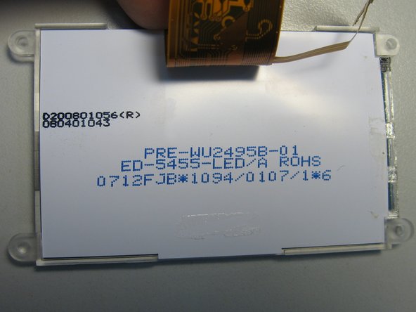
We’ve got around 25 of these soldering stations buzzing away at my workplace, but after 5 or 6 years of hard work, their display backlights started to fade. Without that backlight, the display becomes nearly impossible to read! So far, 4 stations have joined the backlight blues, and I’ve decided to dig a little deeper. Back in the day, Ersa didn’t sell replacement displays separately; they made you cough up a hefty 160 EUR for a new control board, which is nearly half the cost of a brand-new soldering station. Thankfully, today you can snag replacement displays under the catalog number 3EBLCD128x64 for just 33 EUR. However, when I looked for options, the only place I found was an American e-shop, and shipping to Europe starts at around 100 USD. Better than before, but still not the best deal (50 USD for the displays plus 100 USD for shipping). These displays are probably made somewhere in China, but I couldn’t track down their original manufacturer, nor could I find other sources like Ebay or Alibaba. If anyone discovers them, please drop a note in the comments! Here are the markings on the back of the display: PRE-WU2495B-01 ED-5455-LED/A ROHS 0712FJB*1094/0107/1*6. Anyway, since I couldn’t find reasonably priced new displays, I decided to tackle the challenge of replacing the burnt-out backlight LEDs in the displays. I used LTW-108DCG-HS10 as the replacement LEDs in this guide, but any miniature white LEDs with at least 1000 mcd luminous intensity should do the trick. For more details, check out step 14.
Step 1

Alternatively, you can grab a flat head screwdriver, just be mindful of any potential scratches that might sneak onto the metal faceplate.

Step 2

– Turn the station upside down and take out those four T20 screws like a pro.
– Now, flip the station back onto its base and gently lift the top cover off. You’ve got this!
Step 3

– Grab your trusty pliers or a wrench and twist off those four plastic nuts that are keeping the display snug and secure. You’re almost there!
Step 4

– Gently lift the display towards you like you’re raising the roof!
– Get those small brown bars on either side of the connector to loosen up by nudging them upwards with a spudger or something similar. You’ve got this!
– Now, give that ribbon cable a little tug to detach it from the connector.
Tools Used

Step 6

Keep that golden flexible circuit board strip from doing a little upward dance with the cover tape!
– Gently peel off that white cover tape using a knife or a similar tool. You’ve got this!
Step 7

If you decide to tackle that pesky strip glue residue with some alcohol, just be sure to keep it from sneaking into the layers of your display area. We wouldn’t want any unsightly spots crashing the party!
– Grab a knife or a handy tool and gently press down on the circuit strip to help it break free from the cover tape. You’ve got this!
Step 8

Give that strip a gentle bend—just enough to help it slide back in smoothly later on. You’ve got this!
– Grab a knife or a similar tool and gently work on unpeeling the circuit strip from the plexiglass base. Take your time, we believe in you!
– This strip is snugly held down by a thin, transparent, double-sided tape. As you lift the strip, make sure to keep that tape stuck to the plexiglass. If the tape decides to join the strip on its adventure, use the tip of your knife to guide it back home on the plexiglass.
Step 9

Before you dive into soldering, make sure to lay down some heat-resistant material under the strip. This little trick will save your display’s plastic back cover from any unfortunate melting mishaps. We wouldn’t want any unsightly spots ruining your day, right? Check out the photo where a few sheets of paper are doing the job nicely.
– Gently fold the circuit strip onto the back cover of the display and give it a little weight. This will reveal those pesky original LEDs and some resistors that need our attention.
Step 10

– After taking a closer look at the backlight connections, it became clear why they have a tendency to fail: the clever folks in China who designed the display tried to save some space and cash by wiring the LEDs in parallel.
– But here’s the catch: each LED has its own unique threshold voltage, which means one of them ends up hogging more current and burning out before its time. This unfortunate event causes the other two LEDs to pick up the slack, leading to them burning out soon after.
– To tackle this little conundrum, I opted to switch up the connection based on the lower schematic. I bypassed the original 22R resistors and added a 220R resistor in series with each shiny new LED.
Step 11

– There’s plenty of space on the strip to pop in some shiny new LEDs (look for those red arrows) along with their trusty 220R resistors (check out the green arrows) right on the original solder pads.
– Time to say goodbye to those old 22R resistors! Desolder them and connect their pads with a slim wire for a clean slate.
– Let’s make sure those new LEDs are ready to shine! Hook up a 5V power supply to the “A” and “K” pads on the strip and see the magic happen.
Step 12

– Gently place the circuit strip back onto the plexiglass base, just like laying down a cozy blanket.
– Remember, those new components are a bit wider, so be sure the strip stays snug without any bulging or awkward sticking out. If it feels off, no worries—just peel it back and give it another go until it sits just right and feels secure.
Step 13

– Stick that strip down nice and snug with some fresh tape, like good ol’ brown electrical tape.
– Put the soldering station back together gently and give the display a little test to make sure everything’s working like a charm.
Step 14

– Check out the comparison between the original backlight (on the left) and the new one (in the center). The new backlight shines a bit brighter than the old one. If you want to tone it down a notch, try using larger resistors like 270 or 330R instead of the standard 220R.
– I had a little fun experimenting with some general-purpose VLMW11R2S2-5K8L-08 omnidirectional LEDs. You can see the outcome on the station to the right – it’s a bit dim and there’s some noticeable backlight bleed on the right edge where the LEDs hang out. So, I’d suggest sticking with directional, right-angle LEDs like the LTW-108DCG-HS10 for the best results.
– Keep in mind that new LEDs require less current to produce the same brightness, so they’ll probably outlast your soldering station. This little trick is quite handy; high-brightness LEDs typically generate more light at 2 mA than regular ones do at 20 mA. Plus, they use less power, create less heat, and have a longer lifespan. Pretty neat, right?