How To Replace Google Nexus 5 Screen Guide
Duration: 45 min.
Steps: 24 Steps
In this repair guide, we’ll walk you through the steps to swap out your Google Nexus 5’s faulty display unit. This guide comes in handy if you’re dealing with a cracked glass, an unresponsive touchscreen, or an LCD that’s either pitch black or flickering like a disco light. Remember, if you need help, you can always schedule a repair.
Step 1
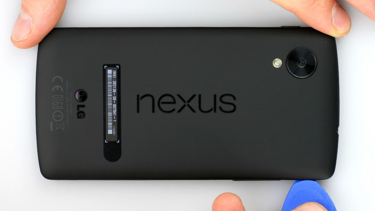
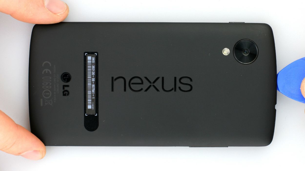
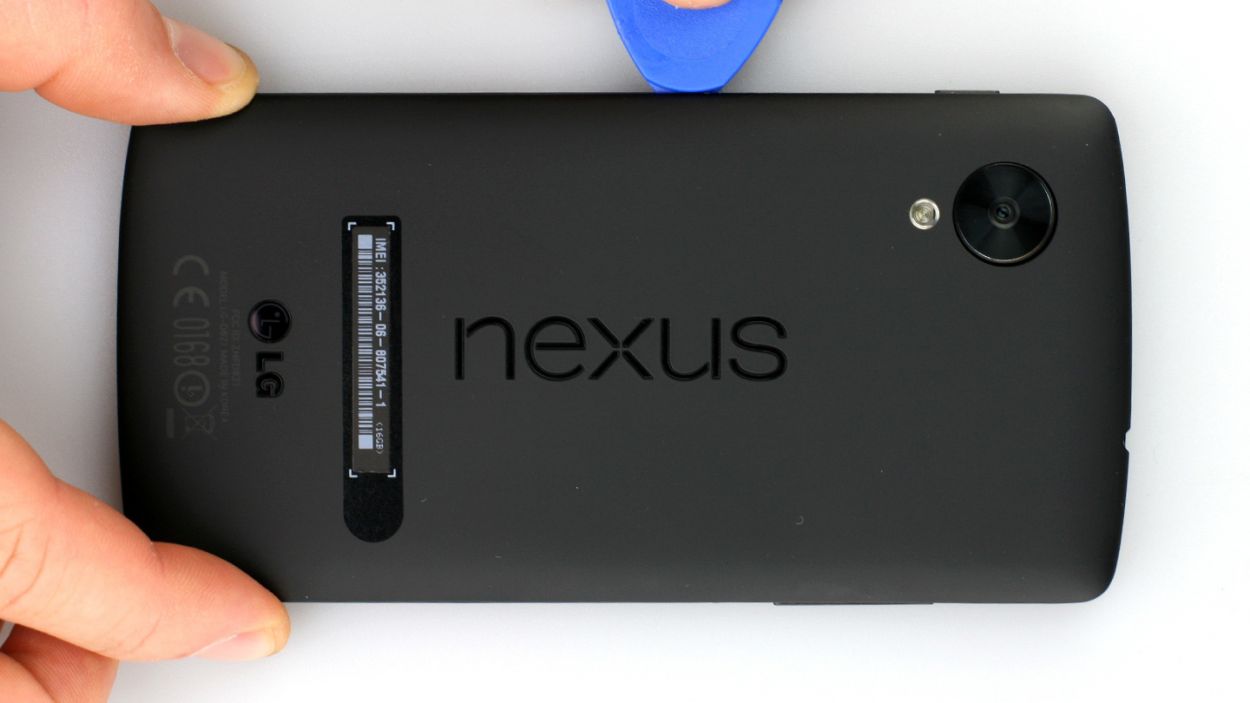
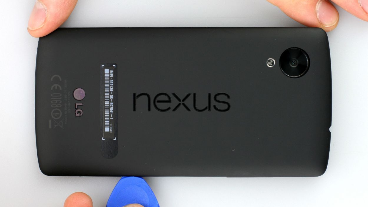
– Slide that hard plastic pick into the little gap next to the volume button. You’ve got 18 retaining clips to disconnect around the back cover, so let’s get to it! Glide the pick all the way around your smartphone, starting from the volume button, past the headphone jack, and right up to the SIM card tray. That’s where it gets a bit easier to pop off the back cover. Just remember, you might need to apply a tad more force in some spots.
– Once you’ve done that, go ahead and lift off the back cover!
Step 2

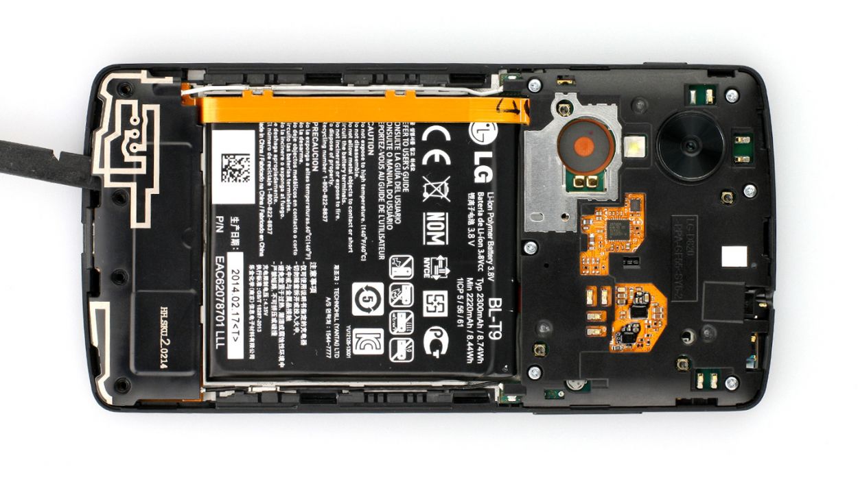
– Alright, let’s get that Google Nexus 5 powered down! Just hold the standby button for about two seconds and follow the on-screen prompt to turn it off.
– Next up, grab your trusty Phillips screwdriver and remove those 4 screws holding the speaker in place (check out figure 1 for a visual guide). We’re talking about 4 x 4.0 mm Phillips screws here!
– Now, it’s time to bring in the spudger! Gently slide it next to the USB connector input (figure 2 will help you out) and lift the speaker right out. Easy peasy!
Step 3

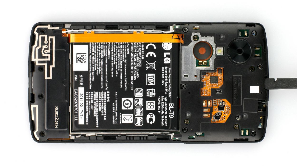
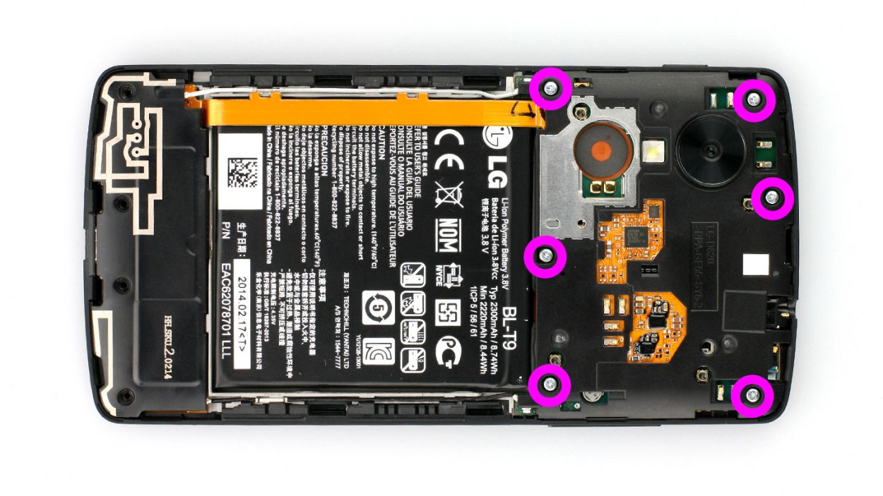
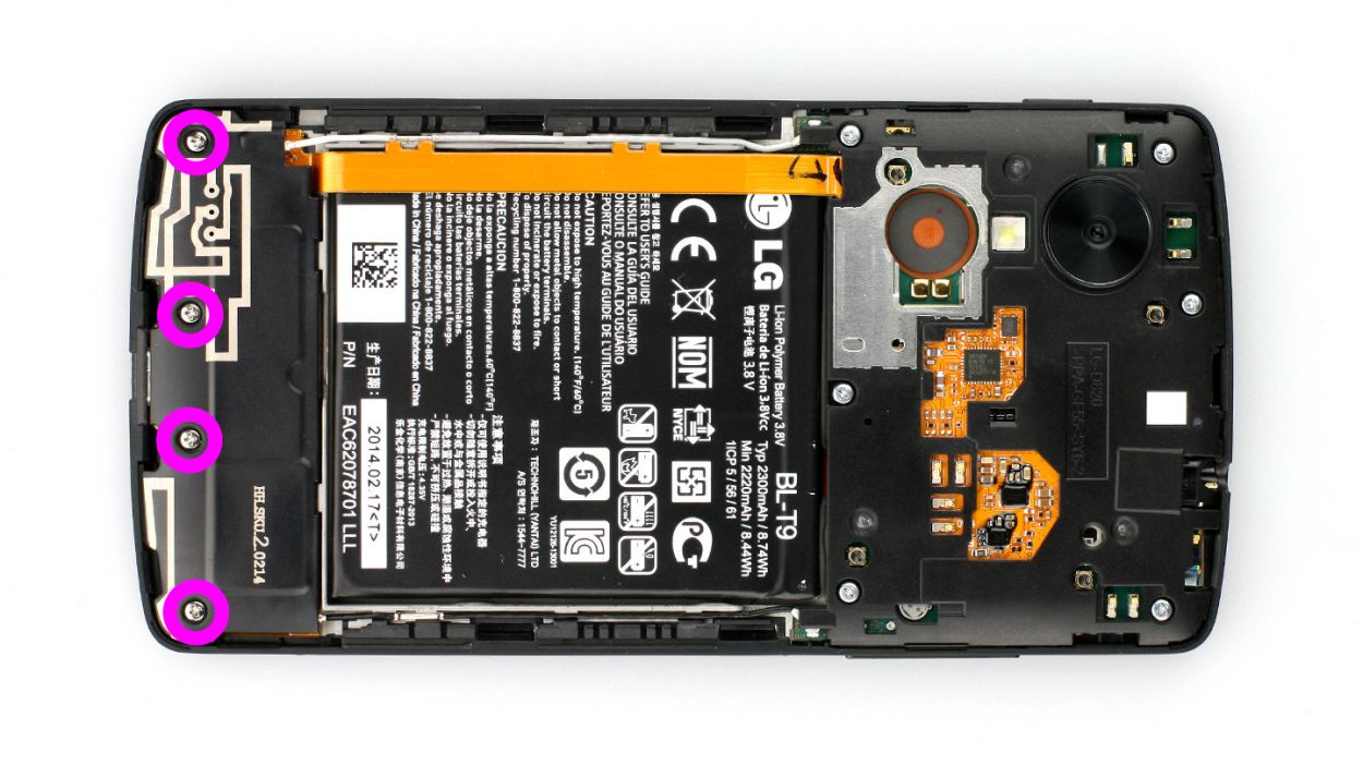
– Remove the 6 Phillips screws that hold the plastic cover in place (see figure 1).6 x 4.0 mm Phillips screws
– Now lift the cover off the logic board by inserting the spudger into the gap next to the headphone output (see figure 2). If necessary, use other leverage points.
Step 4
– Grab your trusty SIM Tool or a good old paperclip to pop that SIM card tray out. Just press the Tool gently into the tiny hole on the tray and watch it slide right out!
Step 5
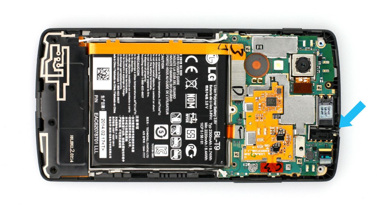
– The headphone jack is snugly nestled in that plastic frame. Gently slide the pointed tip of your spudger into the jack and carefully coax it out. With a little love, it will pop right out!
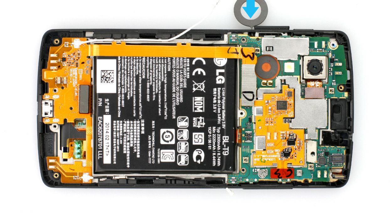
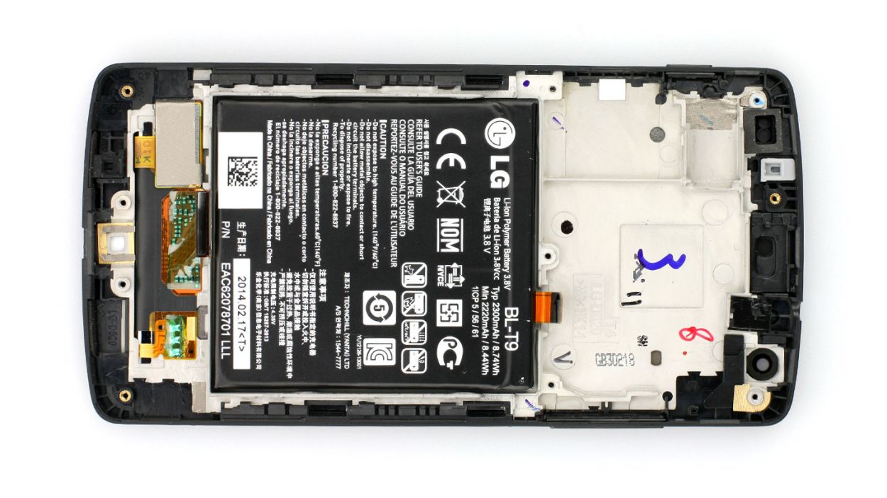
Step 7

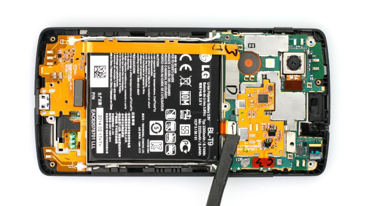
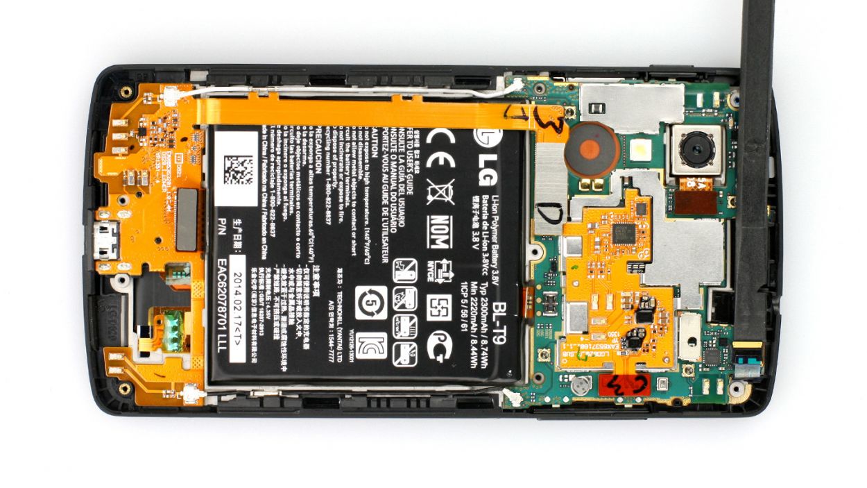
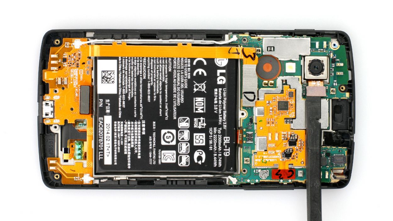
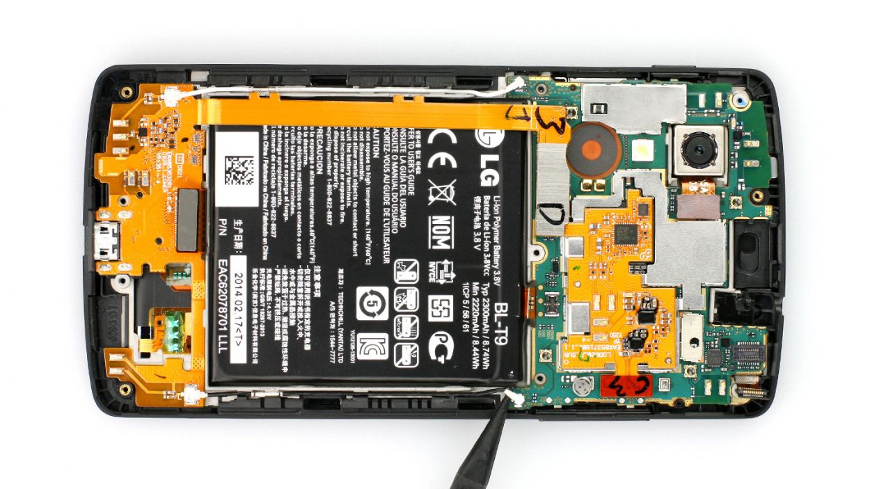
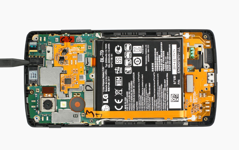
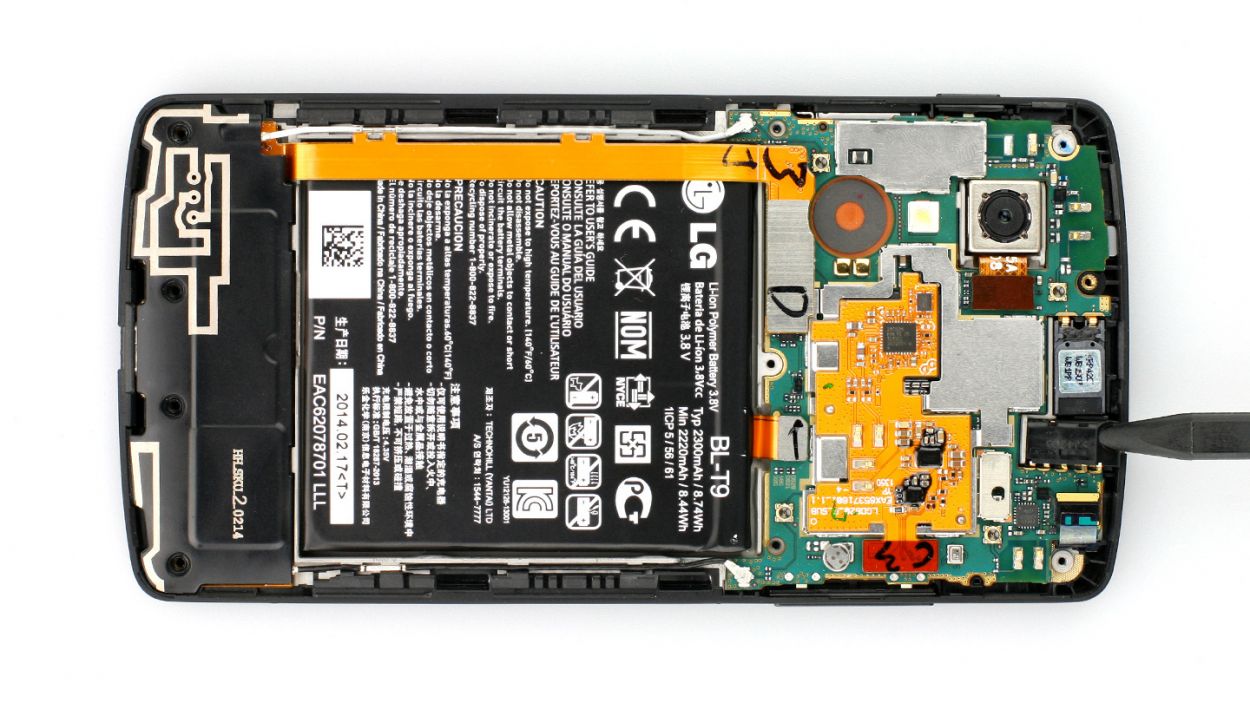
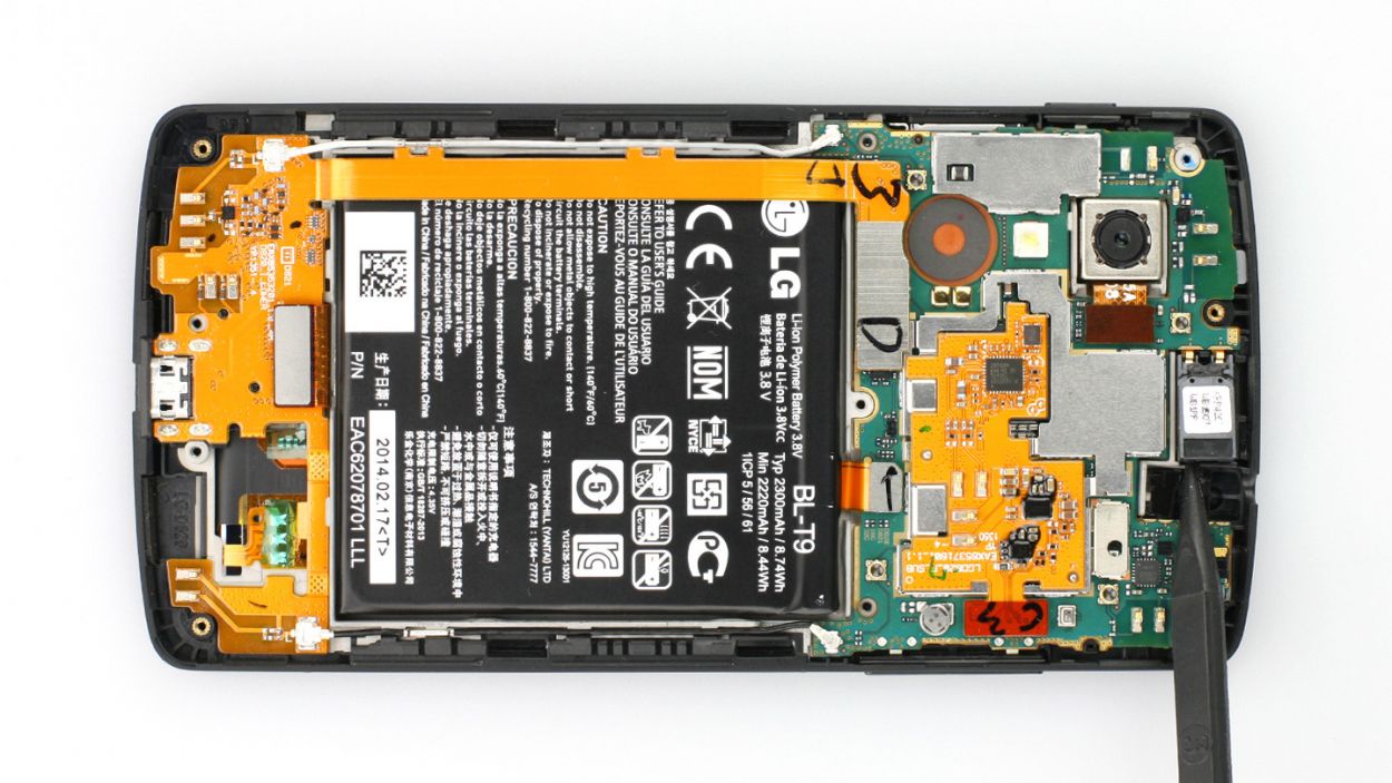
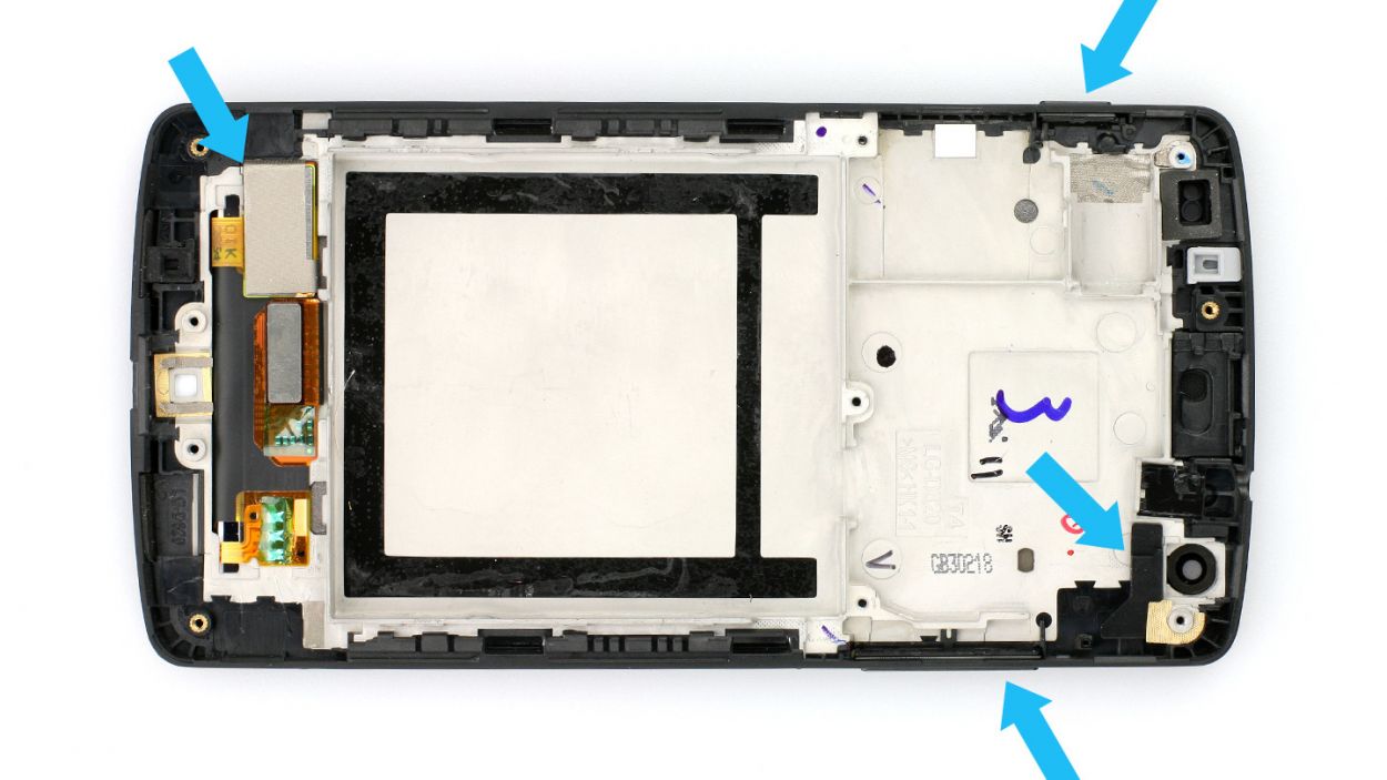
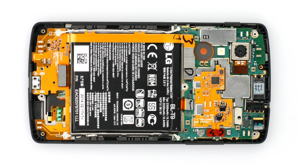
– Alright, it’s time to gently disconnect those highlighted connectors! Just a heads up—be super careful (check out figure 1). We definitely don’t want to accidentally break off those little resistors that are snugly soldered onto the logic board.
– Now, grab your trusty spudger and place the flat end just a smidge below the connectors. Give them a gentle pry to pop them off. The pictures will guide you on where to position the spudger to keep those tiny resistors safe, even if it slips (see figures 2 to 6).
– Next up, let’s disconnect those tiny antenna connectors from the logic board as well (see figures 7 and 8).
LCD
USB port
Battery
Front camera
Rear camera
4 × Antenna
Be gentle with those little resistors on the logic board – we don’t want them getting all bent out of shape! Just take your time and you’ll have that device back in tip-top shape in no time. And remember, if you need any help, the friendly folks at Salvation Repair are always here to lend a hand.
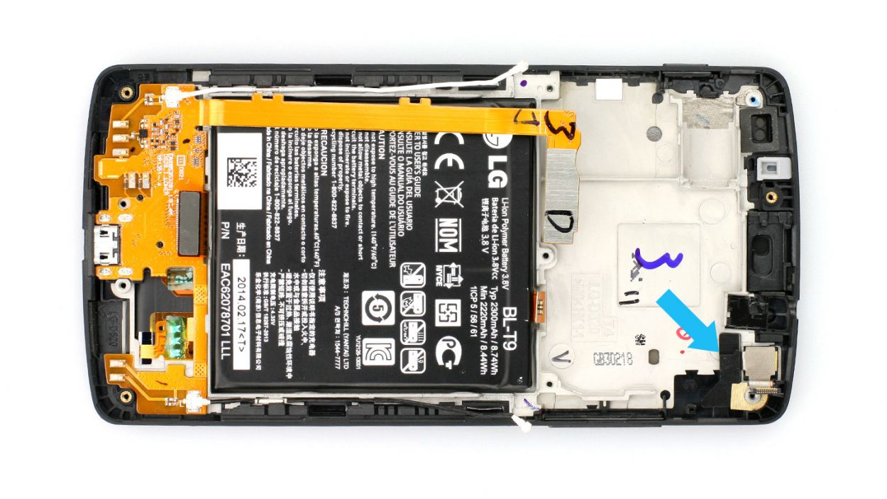
Step 8
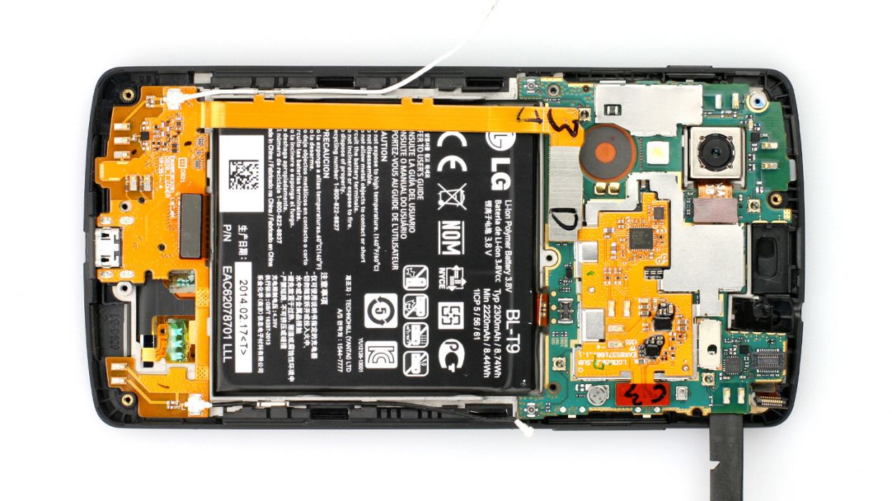

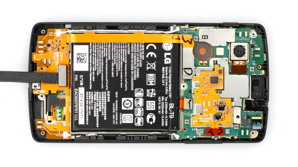
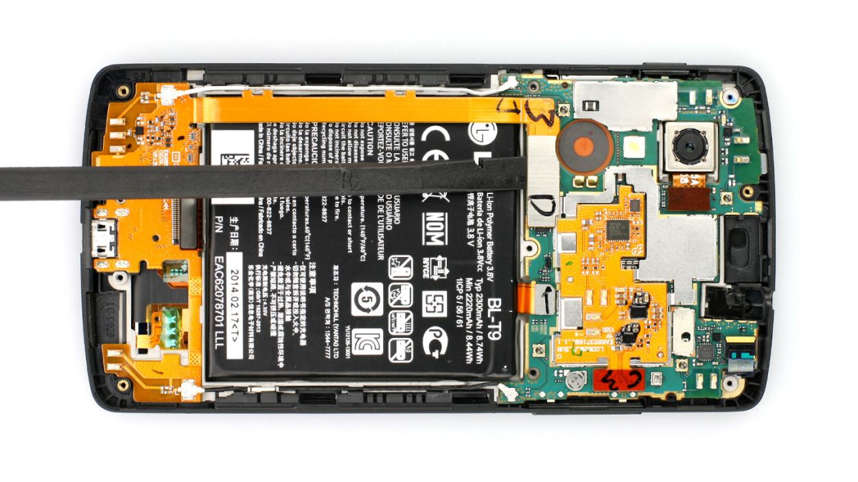
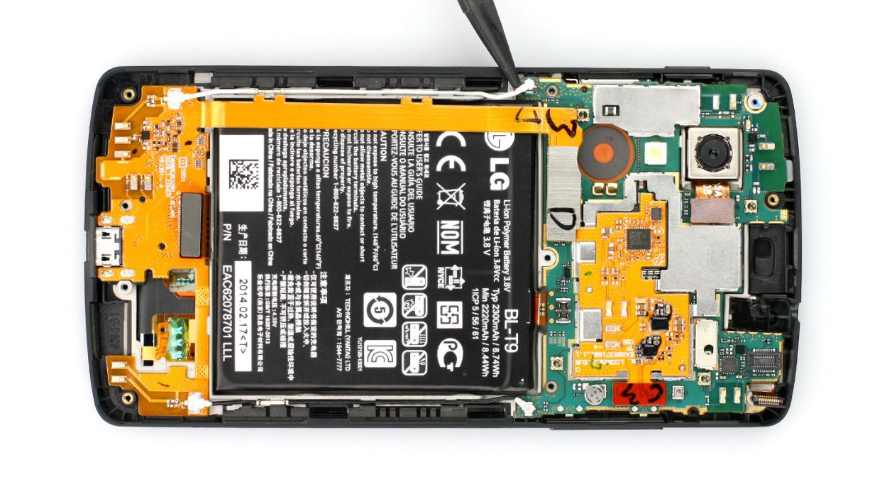
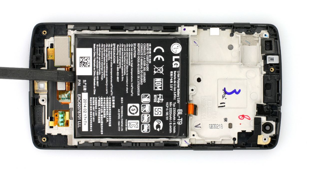
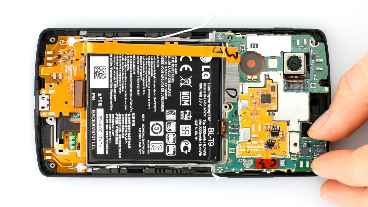
– Time to gently lift the logic board with your trusty spudger! Grab it and slide the flat end under the GPS antenna’s contacts. Give it a little lift and then carefully pop it off with your hands. You’re doing great!
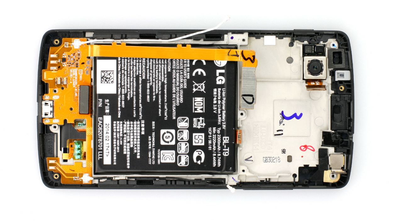
Step 9
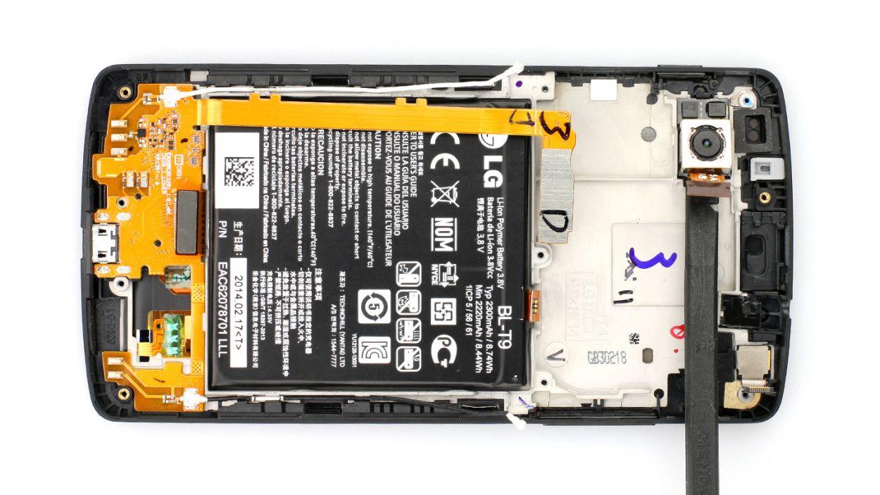
– Time to say goodbye to that rear camera! Gently slide the flat end of the spudger underneath the camera that’s been stuck there like a stubborn sticker.
– Now, give it a little lift and watch it pop out!
Step 10
– Grab your tweezers or use your fingers to gently lift the camera at the connector. It’s still stuck to the plastic frame above with a sneaky adhesive strip, but don’t worry! The end of that strip is cleverly hidden beneath a rubber coating that’s super easy to lift.
– Next up, say goodbye to the front camera. You’ve got this!
Step 11
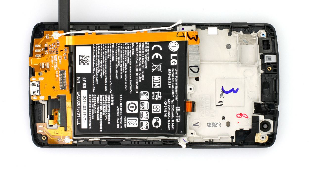
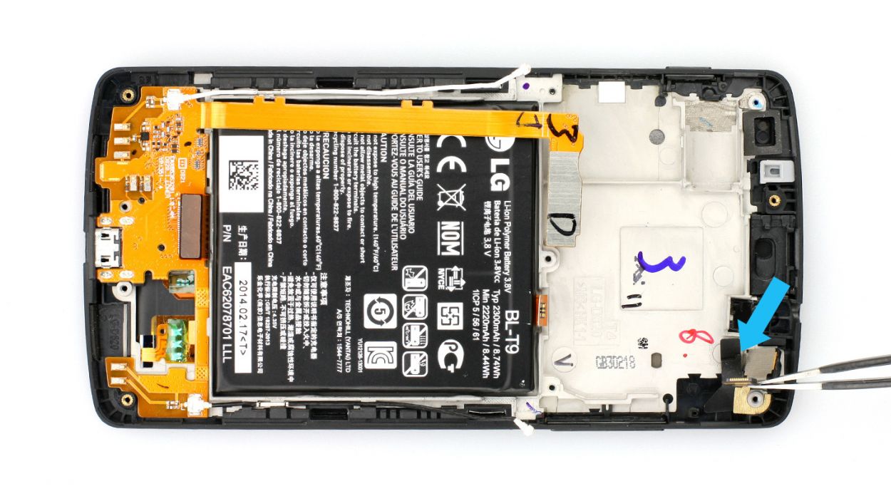
– Slide the spudger gently under the USB connector cable and give it a little nudge to pop it off the base (check out figures 1 and 2 for a visual!). It’s just a bit sticky, so no worries.
– Now, with a steady hand, lift it off carefully.
Step 12
Step 13
– Yo, transfer the rubber coating to the front camera and any other homies that need it.
– Peel the plastic wrap off the new screen’s sticky strips like a boss.
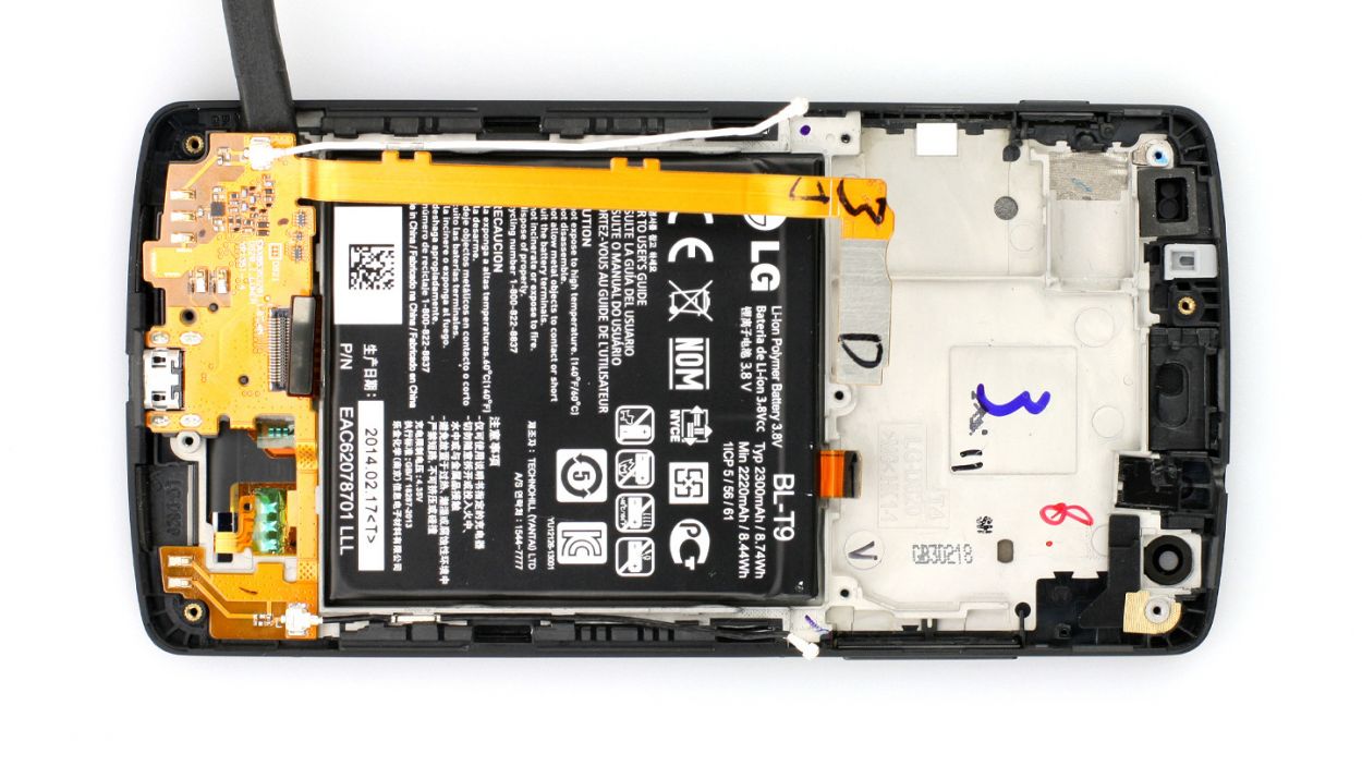
Step 14
– Gently lay the battery in its spot and give it a little press down onto those adhesive+strips+Nexus+5&crid=1TJIMMAJSUJUZ&sprefix=repair+tools%2Caps%2C165&linkCode=ll2&tag=salvationrepa-20&linkId=c486487cf454ce8edd6f5beefab4110f&language=en_US&ref_=as_li_ss_tl’>adhesive strips. It’s like a warm hug for your device!
Step 15

– Alright, let’s get that USB connector cable set back in its rightful place. Just give it a firm press into that plastic frame, and you’re good to go!
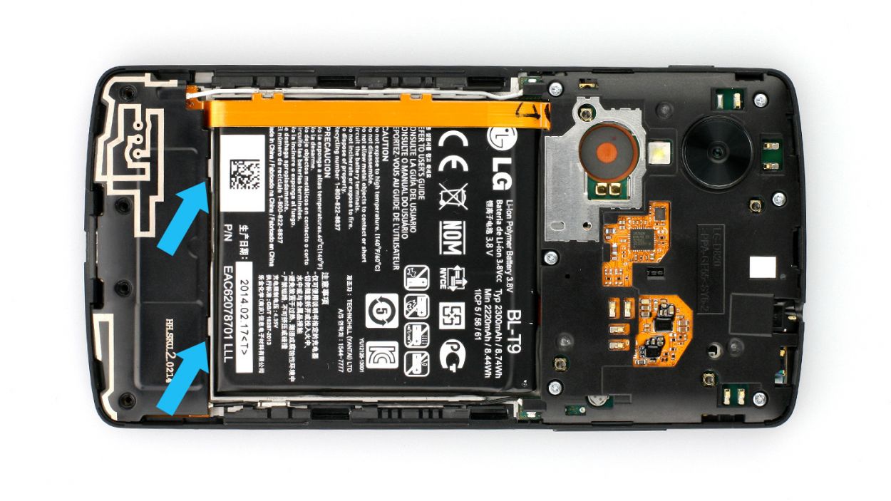
– Next up, we’re gonna nestle that antenna cable right into those handy cable guides next to the battery. Easy peasy!
– If you need any help along the way, you can always schedule a repair with the friendly folks at Salvation Repair.
Step 16
– First things first, gently place that front camera back in its cozy spot, just like it was before.
– Next up, give that adhesive strip a little love and press it snugly beneath the rubber coating once more.
Step 17
– Hey, now that we’ve got all the other bits sorted out, let’s get your main camera looking sharp! Position it where it’s meant to be. Easy peasy!
Step 18
– Gently place the logic board back in its home – make sure it’s snug and comfy!
– Watch out for those antenna connectors; don’t let them sneak under the logic board. Easy peasy!
Step 19
LCD
USB port
Battery
Front camera
Rear camera
4 × Antenna
– Time to plug those connectors back in! Gently but firmly press them into their sockets until you hear that satisfying click. Don’t be shy, but no Hulk-like strength needed!
– Antenna connectors need some love too? Hook those babies up if your device needs them.
Step 20

– Now put the earpiece back in the appropriate position. The adhesive strip should still be sticky enough.
Step 21
– Now put the new headphone output in the appropriate position. Carefully press on the part between the earpiece and the logic board. This step is a bit tricky.
Step 22
– Put the black plastic cover on the logic board and gently press it on.
– Fasten the 6 Phillips screws that hold the cover in place again.6 x 4.0 mm Phillips screws
Step 23
– Put the speaker back in the appropriate position and make sure it’s embedded properly (see figure 1).
– Fasten the 4 Phillips screws that hold the speaker in place again (see figure 2).4 x 4.0 mm Phillips screws
Step 24
– Snapping that back cover on is a piece of cake! Just line it up perfectly and give it a nice, firm press all the way around. You’ll hear it click into place when it’s snug. If you need help, you can always schedule a repair