How to Replace Google Pixel 8a Loudspeaker: Step-by-Step Guide
Duration: 45 minutes
Steps: 40 Steps
Hey there! This guide was put together by the team at Salvation Repair. We think it’s pretty awesome, but if you need help, you can always schedule a repair.
Welcome to your trusty repair guide! Ready to bring back the music? Follow these steps to remove or replace the loudspeaker in your Pixel 8a. If your speaker sounds crackly, has static, or isn’t making a peep, it’s time for a replacement! Grab your new back cover and flash unit adhesives for a successful fix. Just a heads up: any repair might impact your phone’s water resistance, so make sure to seal that back cover nice and tight to keep the water out. Let’s get started!
Step 1


Before you dive into this repair adventure, make sure your Pixel’s battery is below 25%. A fully charged lithium-ion battery can be a bit of a drama queen if it gets damaged!
Simultaneously press the power button and the volume up button to unveil the magical shutdown menu!
– Time to set your phone free! Unplug all those cables and let it breathe.
– Now, give it a little break—totally power down your phone. It’s like a mini vacation for your device!
Step 2


– Gently but confidently insert your trusty SIM eject tool, a straightened paper clip, or whatever clever item you’ve got handy into the SIM card tray hole on the left side of your phone. Give it a good push until the tray pops out!
– Now, simply lift out the SIM card tray and you’re one step closer to victory!
Step 3


The back cover is held in place with some sticky stuff all around the edges and close to the cameras. To keep your phone safe and sound inside, make sure to keep the following tips in mind:
– Just a friendly reminder: keep your tool within 3 mm (that’s about the width of the flat end of your opening tool) as you work around the edges. Let’s keep it safe and snug!
– And hey, steer clear of poking your tool under the edges of that camera bump. We want to keep everything in tip-top shape!
Step 4


Your opening tool is like a superhero with two superpowers: a flat end and a curved end. For this step, we’re using the flat end like a trusty sidekick. Angle it so the tool’s sharp edge points upward. It’s all about getting that perfect angle for a smooth opening.
– You’re all set to start de-gluing! Gently Insert the edge of our trusty opening tool between the back cover and the frame with a sharp little corner leading the charge. Now let’s break free from those pesky adhesives! Worried it’s a bit tricky? You can always schedule a repair if you need help.
Step 5


– Gently glide your opening tool along the bottom edge to break free the adhesive holding the back cover in place.
Step 6


– Let’s slide that opening tool around the bottom right corner and up the right edge, stopping right at the bottom of the camera bump. We’re almost there!
– Now, carefully remove your opening tool from under the back cover. Smooth sailing from here!
Step 7


– Gently slide your trusty opening tool under the top right corner of the back cover, right above that camera bump. You’ve got this!
– Now, glide that tool along the top edge, and stop right at the top left corner, just above the camera bump. Keep it steady!
– Carefully lift your opening tool out from beneath the back cover. Easy peasy!
Step 8


– Gently slide your trusty opening tool under the left edge of the back cover, right below that camera bump you know so well.
– Now, glide that tool down the left edge to break free the adhesive holding everything together.
Step 9


There’s a nifty strip of adhesive right above the camera bump that keeps the top edge of the back cover snug as a bug.
Feel free to slide that opening pick in more than 3 mm along the top edge. You’ve got this!
– Let’s get that back cover off! Start by gently slipping an opening pick under the top left corner of the back cover. Keep going until that pick is just about touching the top edge of the camera bump.
– Now, slide that pick to the right. Keep sliding until you hit the right edge of those cameras. You’re doing great!
Step 10


A final strip of adhesive just beneath the camera bump keeps that back cover snug as a bug!
– Slide the flat edge of your trusty opening pick right under the back cover, just below that camera bump—it’s your secret weapon!
– Now, grab a second opening pick and pop it into the same spot on the other side. You’ve got this!
Step 11


Handle the back cover with care—no bending allowed! If the adhesive is being a bit stubborn, give the cover a gentle wiggle from side to side to help loosen things up.
If that adhesive is stubborn and doesn’t want to budge, you can give the back cover a little heat. Just below the camera bump, gently warm it up with a hairdryer or iOpener. It’ll soften the adhesive and make things a bit easier for you.
– Grab both picks and work them together to pry up the back cover. Keep steady pressure to pop that last bit of adhesive free.
Tools Used


Step 12


– Time to pop off that back cover!
– As you start putting everything back together:
– This is a perfect moment to give your phone a little test before sealing it up. Turn it on and make sure it’s functioning smoothly. Don’t forget to power it down again before you wrap things up.
– Check out this guide to put on some fresh adhesive and get that back cover back in place.
Step 13


Just warm up that flash until it’s cozy to the touch! Remember, the battery and nearby bits can be pretty sensitive to heat, so let’s keep it cool and safe.
If you want to get a bit crafty, consider using an iOpener or a heat gun to gently warm up that flash. It can make your life a whole lot easier!
– Grab your hair dryer and give that flash unit a little warmth! This’ll loosen up the adhesive holding it to the logic board cover. Just like a warm hug for your device!
Tools Used

Step 14


Whoa there, cowboy! Those flash cables are like graceful giraffes – super duper delicate, so handle ’em like a pro and keep those paws steady!
Step 15


As you tackle this repair, remember to keep an eye on every single screw—each one has its special spot, and we want them to find their way home!
The Pixel 8a loves Torx Plus screws, but don’t sweat it if you have standard Torx bits—they’ll do the trick! Just remember to apply steady, downward pressure to keep things from going sideways.
– Grab your trusty Torx Plus 3IP screwdriver and let’s tackle those 15 screws holding the logic board cover in place:
– You’ll be removing thirteen screws, each measuring 4.3 mm long.
– And don’t forget those two tiny screws, each just 1.9 mm long.
Step 16


Take care not to mess up those spring contacts hugging your phone’s edge! Only use your tool in the designated spots, and you’ll be golden.
– Slide an opening pick under the bottom right corner of the logic board cover and gently pry it up to pop that clip free. You’ve got this!
– Carefully insert the tip of a spudger under the notch near the top right corner of the logic board cover (just below the screw hole) and give it a little nudge to release that clip. Easy peasy!
Tools Used

Step 17


– Gently lift the top edge of the logic board cover and guide the flash unit through its designated cutout, taking your time to ensure a smooth fit.
– When putting everything back together, simply thread the flash through its cutout as you lower the logic board cover back into place. You’ve got this!
Step 18


– Time to take off the logic board cover! This little piece is like a cozy blanket for the wireless charging coil, and we need to remove it to keep things moving smoothly.
Step 19


– Grab a trusty pair of tweezers or your fingers and gently pop off the metal cover located on the right edge of your phone. You’ve got this!
– When it’s time to put everything back together, make sure to tuck the upper left corner of the cover under the hook on the logic board before laying it down in place. Easy peasy!
Tools Used

Step 20

This guide is based on the Verizon model (G8HHN) of the Pixel 8a, which comes with an additional cable and connector specifically for the 5G mmWave antenna, located just to the left of the battery connector. If you happen to have the non-mmWave version, feel free to breeze past any steps that reference the antenna cable. You’re in for a smooth repair experience!
Step 21


Don’t go wild with that prying tool! Stick to the instructions to keep those delicate bits around the battery and 5G mmWave connectors happy.
To reconnect a press connector, just line it up with the socket and gently press down on one side. It’ll click into place. Then, press down on the other side. Sometimes you might need to try a few times to get the connector just right.
– Slide the flat end of a spudger under the right edge of the battery connector and gently lift it straight up to disconnect it. You’ve got this!
Tools Used


Step 23


– Grab your trusty Torx Plus 3IP screwdriver and get ready to unscrew! Carefully remove the 4.3 mm-long screw that’s keeping the earpiece speaker snugly attached to the frame. You’re doing great!
Step 24


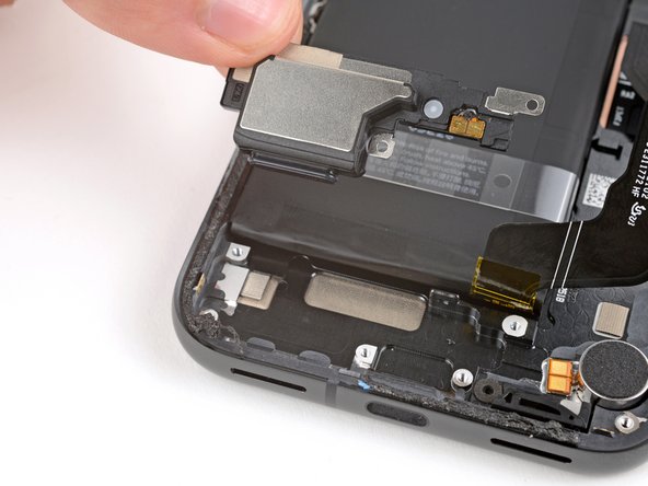
– Grab the bottom edge of the earpiece speaker and gently lift it out. Easy peasy!
– When you’re popping the speaker back in during reassembly, just a quick heads up: keep that graphite film out of the way. Insert the speaker at a slight downward angle and nudge it towards the front of the phone so that the gasket fits nicely into its cozy spot in the frame. You’ve got this!
Step 25


– Grab a Torx Plus 3IP screwdriver, and let’s get those two 4.3 mm-long screws out of the way that are holding the antenna housing in place. You’ve got this!
Step 26


– Slide an opening pick under the left side of the antenna housing and gently pry it up to pop those clips loose.
– Now, give the top edge some love and repeat the pick action to free the last of those clips.
– When you’re putting it all back together, give a nice firm press around the edges of the housing to snap those clips back in place.
Step 27


– Time to give that antenna housing a little lift! Gently remove it and set it aside. You’re doing great!
Step 28


Watch out for those rear camera lenses during the next two steps! Let’s keep them safe and sound.
– Gently wedge the spudger or your trusty fingernail to lift up and disconnect the press connector just above the battery.
Tools Used
Step 29


If your pick is having a tough time slipping under the cable, give it a gentle blast of warmth from a hair dryer or heat gun. This will help loosen up that stubborn adhesive hiding underneath.
– Now, let’s get that front-facing camera cable out of the way. Gently slide the tip of your opening pick under the right edge of the cable and give it a little lift. That’s all it takes to detach it!
Tools Used


Step 31


Hey, those spring contacts on the logic board are pretty delicate! Be gentle with your tool, and just use it where we tell you to. You’ll be rockin’ in no time!
– Gently slide the spudger tip under the notch at the top right corner of the logic board and give it a little nudge to unclip the board. You’ve got this!
– Now, let’s do the same on the other side. Use the notch next to the cameras to carefully pry that side free. Keep it smooth and steady!
Tools Used
Step 32


Hey there! The logic board is super sensitive, so take it easy and don’t twist it too much as you gently pry the lower edge away from the frame.
Hold on a sec! Don’t yank the logic board out just yet; it’s still hanging on to the frame with the screen cable.
Before attempting to disassemble, double-check that you’ve removed the SIM card and that the flash, front-facing camera, and press connector won’t get stuck underneath.
– Time to give that logic board a little lift! Gently lift the top edge of the logic board away from the frame.
– Now, pull the top edge of the logic board to the right side of the frame. You’ll see those cutouts on the board – they’ll need to clear the vibration motor and some other bits in the frame.
– As you keep pulling, the charging port will pop right out of its little home in the frame.
– When you’re putting everything back together, push the logic board towards the bottom of the frame and press down on the charging port. Make sure the bottom edge of the board is snug against the frame – you want a nice, tight fit!
Step 33


Hey there! Just a heads up, the logic board might decide to wiggle out of its cozy spot during this step. Keep it steady, but please don’t grab it by any of those delicate camera lenses or connectors!
And remember, those thermal pads on the underside of the logic board are a no-touch zone. Keep your fingers clear!
If you don’t have a suction handle handy, no worries! Just lean your phone against something solid, like a hefty box or a thick book. You’ve got this!
– Pop a suction handle on the left side of the screen with the handle facing down.
– Lift the left side of your phone so it’s standing upright.
– Lower the logic board and lay it flat, gently guiding the delicate graphite sheet around the cables.
Tools Used

Step 34


Watch out for that battery! We don’t want any surprise punctures during this step.
Keep one hand hovering above the display bracket while you carefully pry it up—it’s known to pop out unexpectedly.
Be super cautious not to mess up the board hiding beneath the bracket’s socket. Just nudge your tweezers in enough to lift the bracket without causing a ruckus.
If your display cable bracket has taken a little bendy vacation and no longer fits just right, it’s time to swap it out for a shiny new one!
– Gently use the tip of one arm of your angled tweezers to lift the top edge of the display cable bracket from the center of the logic board. Careful now, we don’t want any surprises!
– Next up, it’s time to remove that bracket. You’ve got this!
– When you’re putting it all back together, just hook the bottom edge of the bracket into its little home on the logic board and give the top a firm press to snap it back into place. Easy peasy!
Tools Used
Step 35


– Gently slide the flat end of a spudger or a clean fingernail under the top edge of the display cable press connector and pop it up to disconnect.
– This cable’s got some serious attitude and can be tricky to reconnect. If needed, hold the neck of the cable in place with tweezers and line it up over the socket before pressing down to secure.


Step 37


Hey there! Keep those fingers and tools away from the sensor. We don’t want to mess up this delicate part, alright? 😉
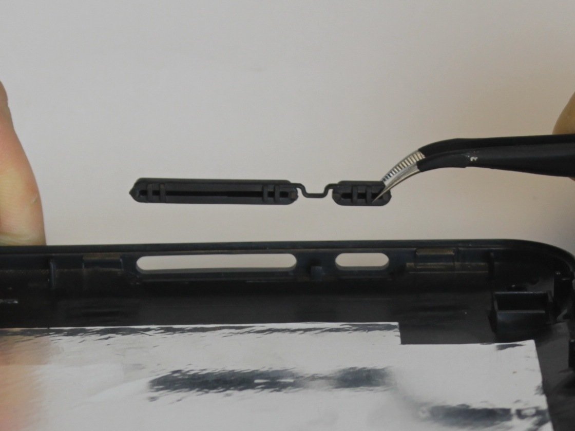
– Hey, if that little rubber gasket stuck to the frame or got a little wonky, gently peel it off and set it aside. You’re doing great!
– Now, when you’re putting everything back together, make sure that gasket hangs out over the front sensor on the logic board. The smaller opening should be pointing toward the top. You got this!
Step 38


– Alright, time to put it all back together! First things first: take a peek at those thermal pads. You’ll find them lounging at the bottom of the logic board or chilling in their designated spot on the right side of the frame.
– If you’re giving your old logic board another shot and notice any unfortunate wear and tear on the thermal pads, it’s time for a swap! Gently peel off the old pad, give the surface a good clean with some strong isopropyl alcohol (aim for something over 90%), and pop on a fresh pad.
– Got a shiny new logic board that’s missing its thermal pads? No problem at all! Make sure to slap those new pads on now before you seal everything up.
Tools Used

Step 39


Alright, don’t go poking around near the battery with your tool! Just follow the instructions and make sure your tool is between the metal bit and the loudspeaker. It’s like a little dance, you know? Just keep it moving smoothly.
– Gently slide the tip of your opening pick into the little space between the top edge of the loudspeaker and the metal bump on the frame. You’re doing great!
– Now, with a bit of care, lift the loudspeaker up to free it from the frame. Keep it steady!
Step 40

– Ready to put your device back together? Just retrace your steps in reverse and you’ll be golden!
– Want to check if everything’s working perfectly? Give the built-in diagnostic tool a whirl by clicking here.
– Got some e-waste? Make sure to drop it off at an R2 or e-Stewards certified recycler. It’s good for the planet!
– Things didn’t go quite as expected? No worries! Give some basic troubleshooting a shot, or reach out to our awesome community for a hand.
– Decided to take a break? No problem, just let us know you didn’t finish this guide.
–
Success!