How To Replace Google Pixel 9 Pro Fold Loudspeaker – DIY Guide
Duration: 45 minutes
Steps: 109 Steps
This repair guide was created by our awesome team at Salvation Repair. While we’re not officially backed by any big names, we’re here to help you every step of the way! For more info on our repair guides, check it out here.
This guide is brought to you by the awesome folks at Salvation Repair. While we’re not officially backed by any big names, we’re here to help you tackle the task of replacing the loudspeaker in your Google Pixel 9 Pro Fold. Dive in and let’s get that sound back in action! If you need help, you can always schedule a repair.
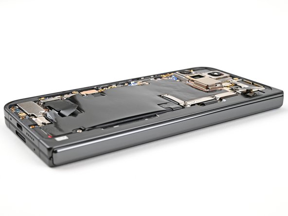
Step 1

– Disconnect all cables from your phone and make sure to power it down completely. Time to give it a little break!
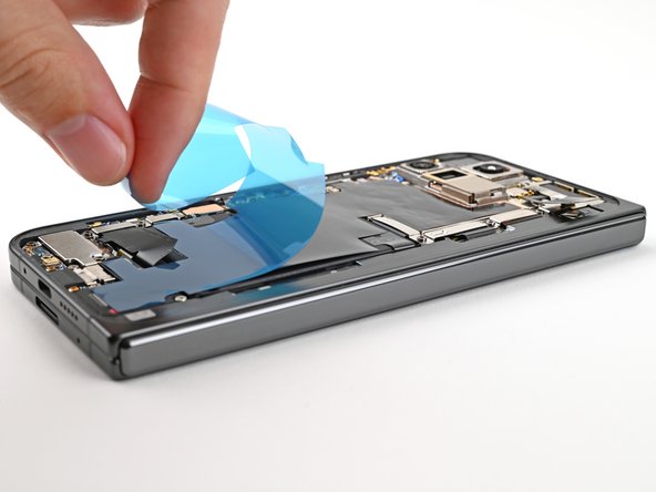
Step 2
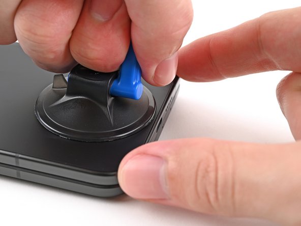


If your back cover’s looking rough, a little clear packing tape might be your best friend to help that suction cup stick. You can also use some super strong tape if the suction cup’s just not having it. In a pinch, even a little superglue on the suction cup can work on that broken back cover. If you need help, you can always schedule a repair.
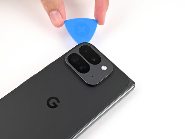
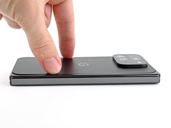
– Stick a suction cup onto the back cover, aiming for the center of the bottom edge.
– Hold the phone steady with one hand and pull the suction cup up with strong, steady force to create a gap between the back cover and the frame.
– Slide an opening pick into the gap.
Step 3

As you tackle the next couple of steps, remember to keep your opening pick no deeper than 3 mm. We want to keep those metal springs around the frame safe and sound!
For a little extra guidance, feel free to measure and mark your opening pick at 3 mm—it’s like giving yourself a visual cheat sheet!
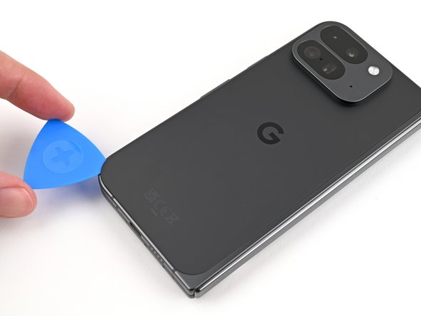
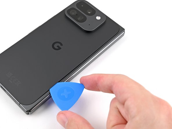
– Gently detach the suction handle from the back cover, like peeling off a sticker.
– Slide the opening pick around the bottom left corner and up the left edge of the back cover to break that adhesive seal. You’re doing great!
Tools Used

Step 4

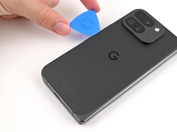
– Keep that pick sliding around the top left corner and glide it along the top edge of the back cover like it’s on a mission!
Step 5
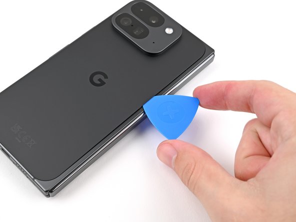

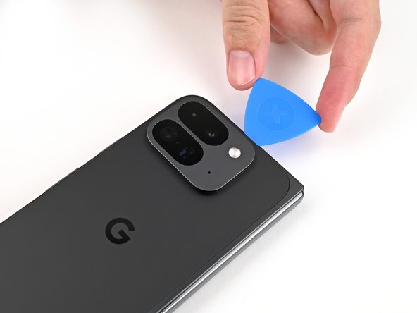
Whoa, there’s some serious sticky action along that right edge of the back cover! Be sure your pick is at least 4 mm deep to give ’em some major separation.
– Gently glide your pick down the right edge and around the bottom right corner to peel away that stubborn adhesive like a pro.
Step 6

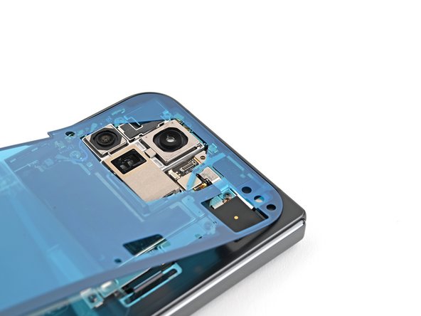
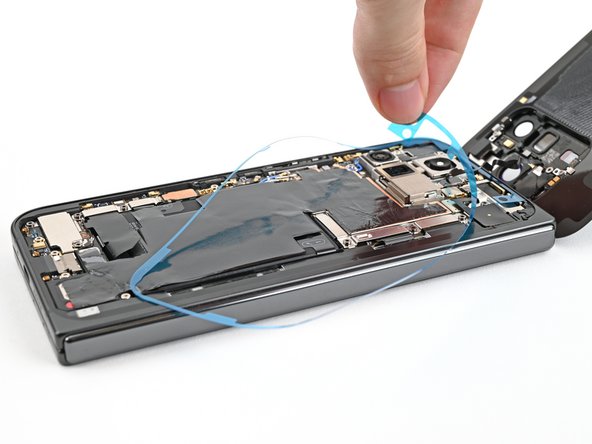
Hey there! Hold on, don’t detach the back cover just yet. You see, it’s still holding hands with your device by a little wire called a cable. Take a gaze at that international connector sorta making a bond!
The back cover should now be loose from the frame. If it’s still clinging on for dear life around the edges, gently coax it free with an opening pick to tackle any stubborn adhesive.
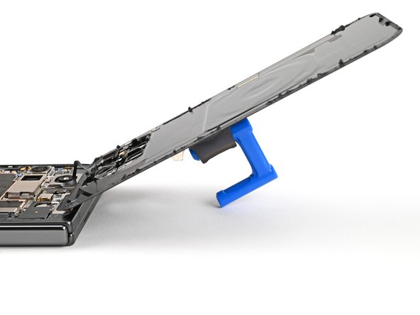
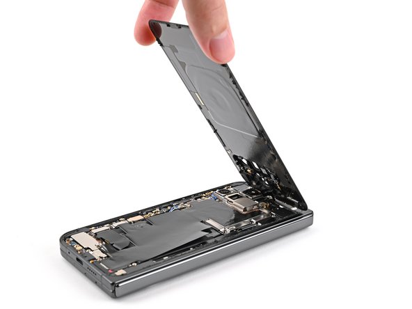
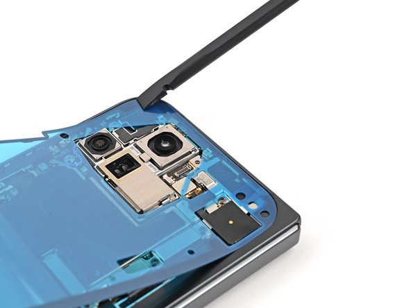
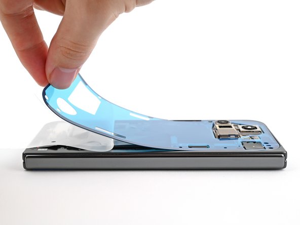
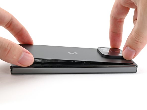
– Gently lift the lower part of the back cover and swing it over the top edge of your phone like you’re opening a treasure chest.
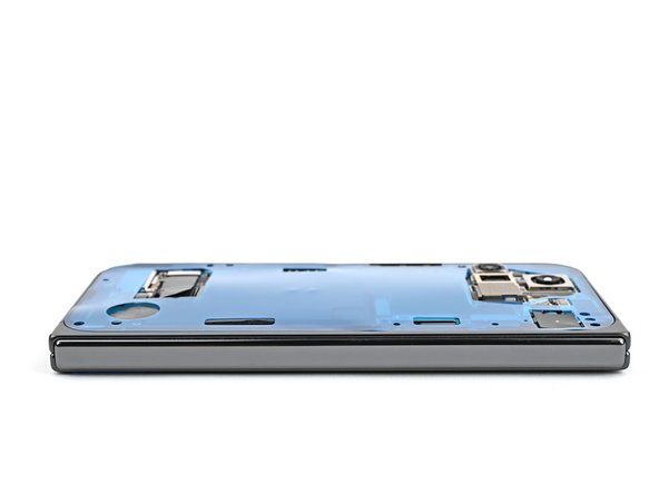
– Support the back cover with a suction handle or a strong, clean object—just be sure that the cable isn’t feeling any tension.
Tools Used
Step 7

As you dive into this repair adventure, keep an eye on each screw and remember to return it to its cozy little home when you’re done.
The Pixel 9 Pro Fold may be rocking some Torx Plus screws, but standard Torx bits can join the party too! Grab a T3 or T4 Torx bit (or just one size bigger) to tackle those 3IP Torx Plus screws, and don’t forget to apply steady, downward pressure to avoid any stripping mishaps.
– Alright, time to get those screws out! Grab your trusty Torx Plus 3IP driver and loosen up that 3.0 mm screw holding down the top bracket. It’s like giving your device a little high-five!
Step 8

– Grab those tweezers or just use your fingers to gently nudge the top bracket upwards, freeing it from its snug little clip.
– Now, go ahead and lift off the top bracket like a pro!
Step 9

Stick to the script with your spudger—veering off course might knock loose some tiny but mighty components. If you need help, you can always schedule a repair.
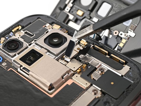
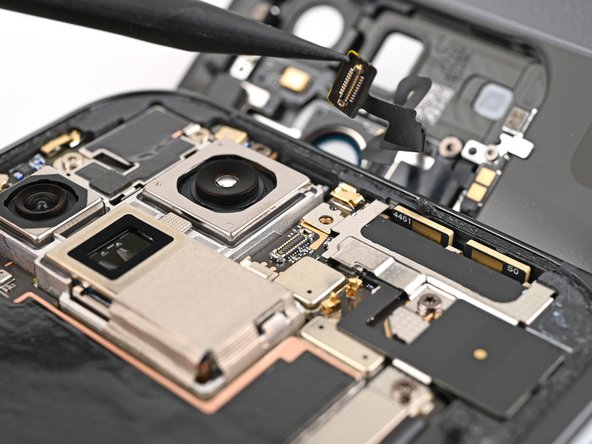
– Gently slide your spudger under the edge of the back cover cable connector—think of it as giving it a little nudge.
– Carefully lift and disconnect the back cover cable. You’ve got this!
Tools Used


Step 11

– Grab your trusty Torx Plus 3IP driver and let’s get to work! Carefully unscrew those two 3.0 mm-long screws that are holding the base battery bracket in place. You’ve got this!

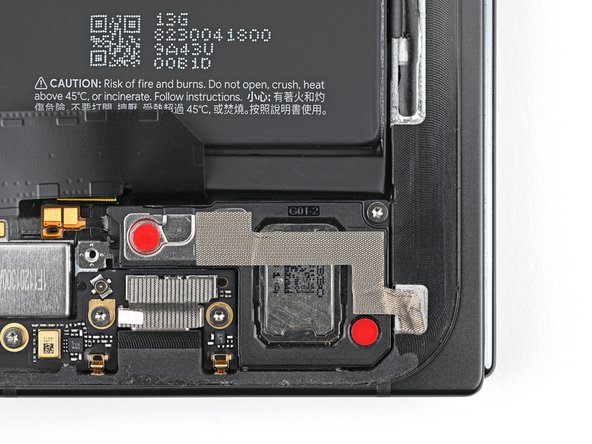
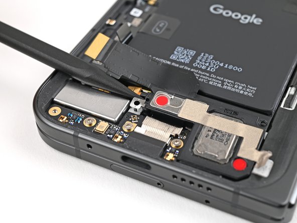
Step 13

Keep your spudger in its designated zone! Straying too far might send those tiny surface-mounted components on an unexpected adventure.
– Gently slide the tip of your spudger under the bottom left corner of the base battery press connector, right by that shiny gold marker.
– Carefully pry it up and disconnect the base battery. You’ve got this!
Tools Used
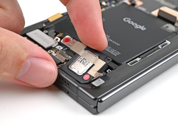
Step 14

– Grab your trusty spudger and gently lift up the USB-C port board cable press connector to disconnect it. You’re doing great!
Tools Used
Step 15


– Grab your trusty Torx Plus 3IP driver and let’s get to work! Carefully unscrew those two 3.0 mm-long screws holding the vibrator bracket in place. You’ve got this!

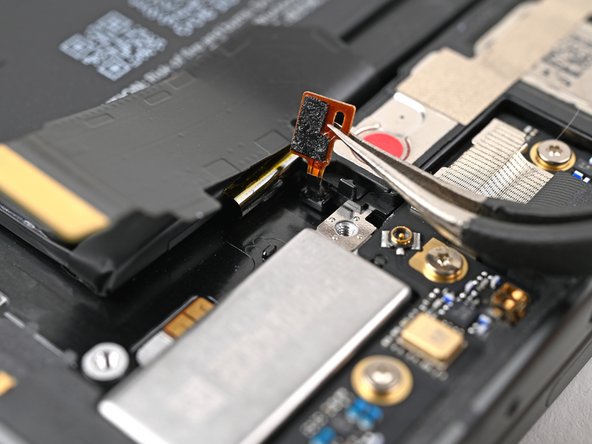
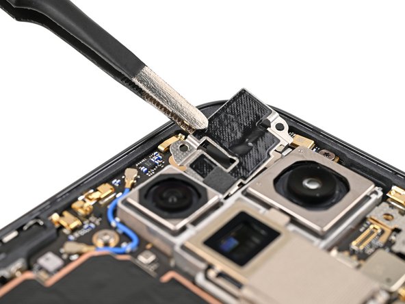
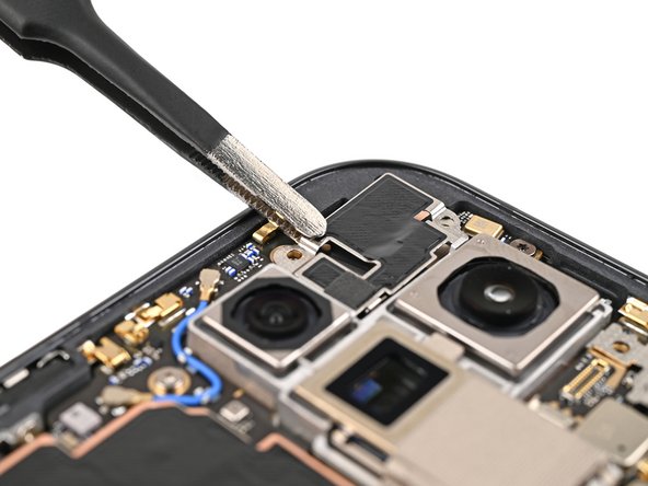
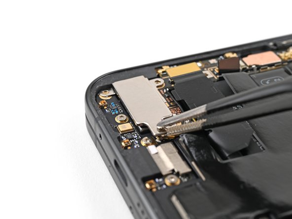
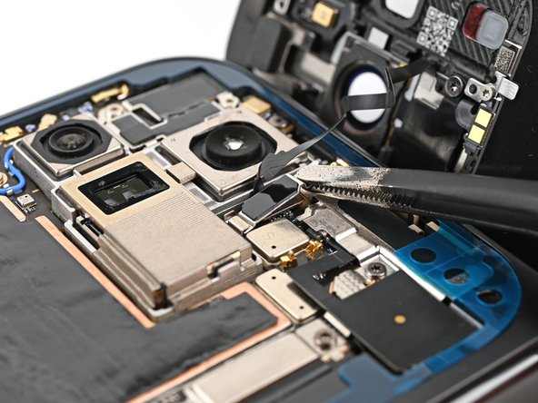
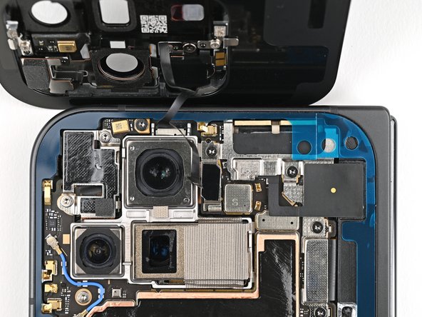
Step 17

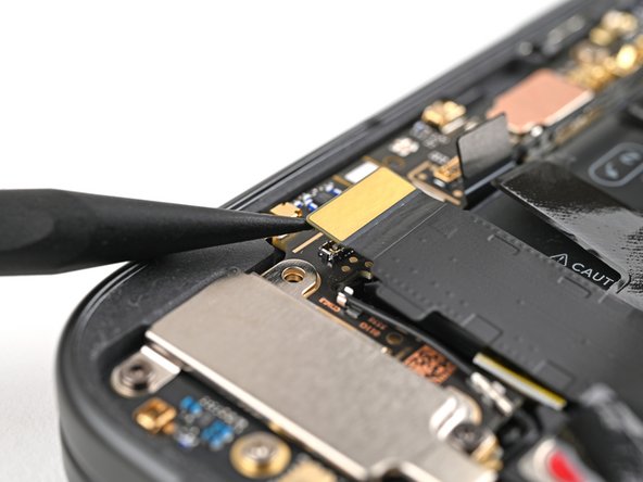
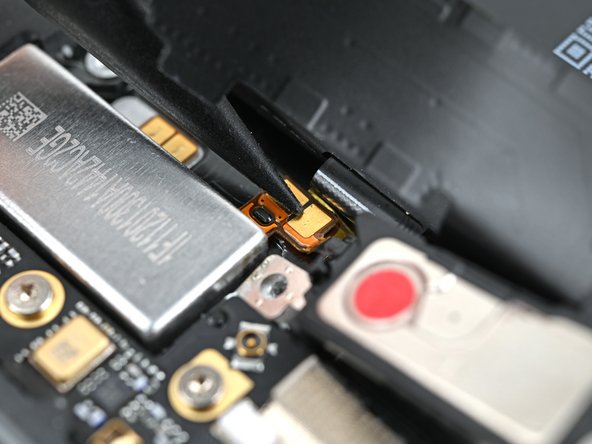
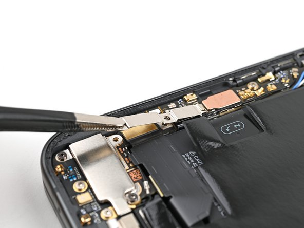
– Let’s give that black antenna cable a little TLC! Gently slide one arm of your angled tweezers under the metal neck of the connector head on the USB-C board.
– Now, give it a lift! Lift straight up to disconnect the cable. Easy peasy!
Tools Used

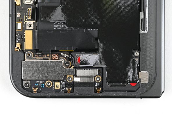
Step 18

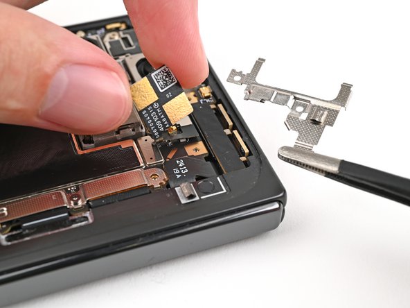
– Grab your trusty Torx Plus 3IP driver and let’s get to work! You’ll want to unscrew the two tiny 2.6 mm screws that are holding the inner front camera bracket in place. Easy peasy!
Step 19


– Grab your tweezers or use your fingers to gently lift the inner front camera bracket up and slide it toward the left edge of the phone to pop those clips loose.
– Now, go ahead and remove the inner front camera bracket. Easy peasy!
Step 20

– Grab your trusty spudger and gently lift up to disconnect that inner front camera press connector. You’re doing great!
Tools Used
Step 21

– Grab your trusty spudger and gently pry up the inner front camera, releasing it from the sticky grip of the adhesive that’s holding it tight to the frame.
– Carefully lift out the inner front camera and set it aside.
Tools Used

Step 23
– Grab your trusty Torx Plus 3IP driver and let’s get to work! Carefully unscrew those two 3.0 mm-long screws holding the ultra wideband bracket in place. You’ve got this!
Step 24

– Hold that ultra wideband antenna aside, and give the bracket a tug towards the phone’s bottom to pop those clips loose.
– Take out the ultra wideband bracket.
Step 25


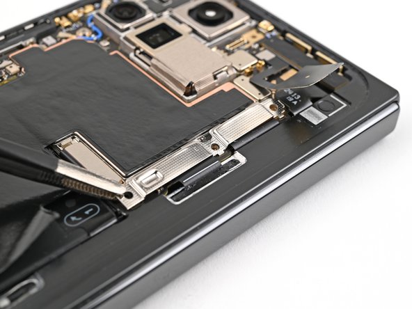
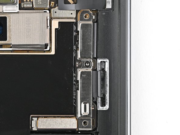
– Grab your trusty Torx Plus 3IP driver and carefully unscrew the 3.0 mm-long screw that’s holding the interconnect cable bracket in place. You’ve got this!
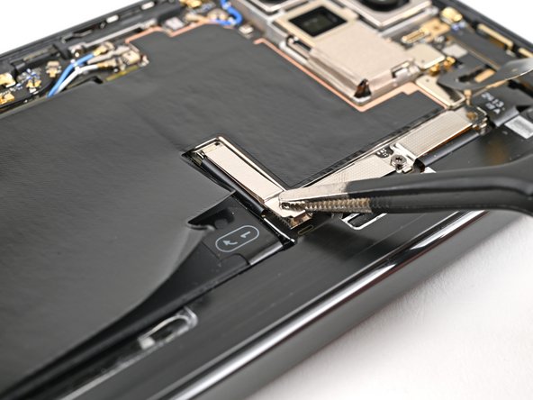
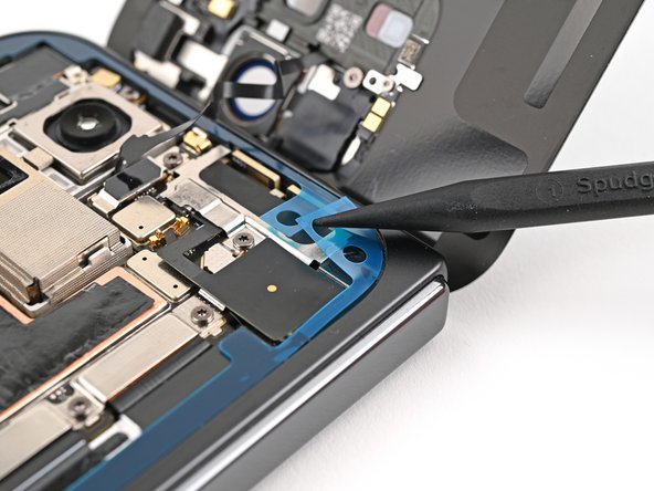
Step 26


– Grab that bracket with your trusty tweezers (or your fingers, if you’re feeling brave!) and give it a gentle tug towards the right side of your phone. It’ll pop right off its clip.
– Now, give that bottom interconnect cable bracket the boot! It’s time to say goodbye.
Step 27


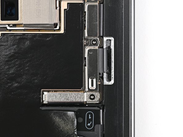
– Grab your trusty Torx Plus 3IP driver and carefully unscrew that 3.0 mm-long screw holding the inner display cable bracket in place. You got this!

Step 29

Stick to the script with your spudger—veering off could knock loose some tiny but crucial parts. If you need help, you can always schedule a repair.
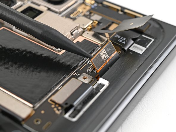
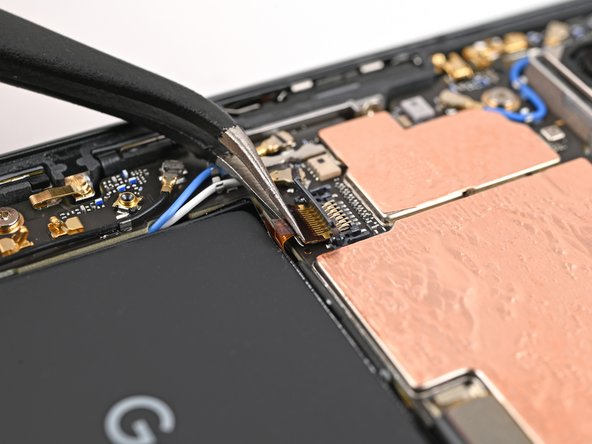
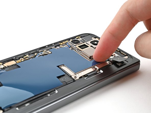
– Gently slide the tip of your spudger under the bottom left corner of the inner display press connector, right by that shiny gold marker on the logic board.
– Carefully pry it up and disconnect the inner display cable.
Tools Used
Step 30
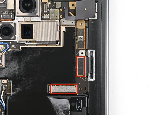
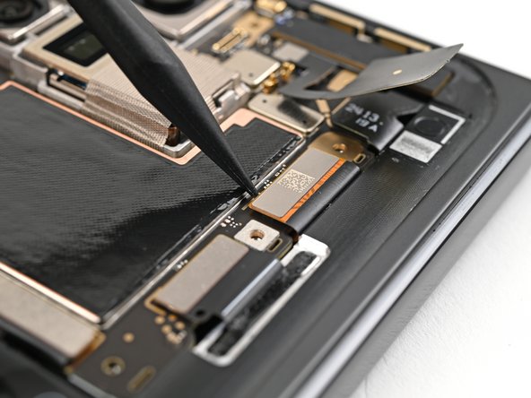
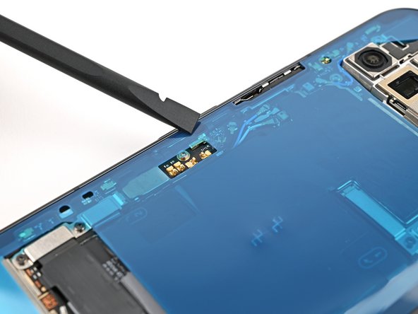
– Give it another go with those sneaky top and bottom interconnect cable press connectors! Just remember to gently pry right next to those shiny gold markers. You’ve got this!
Step 31

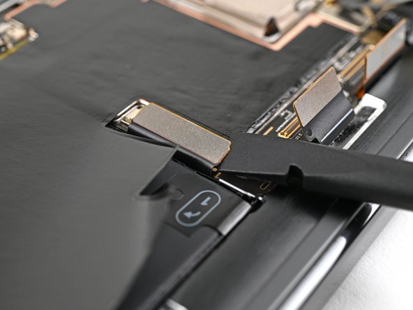
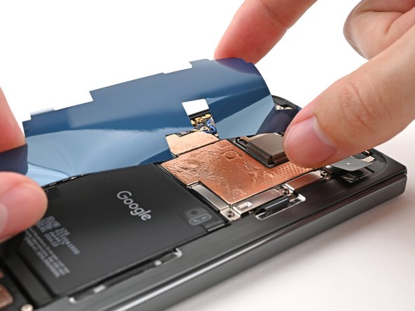
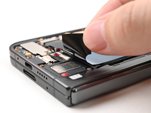
– Gently lift the graphite sheet off the bottom speaker to break the adhesive that’s holding it in place. Let’s get that separation going!
Step 32
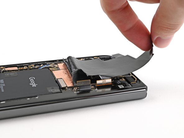

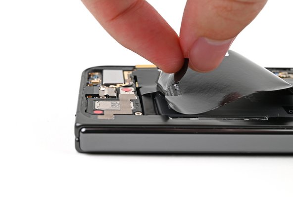
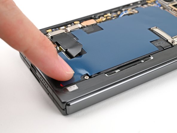
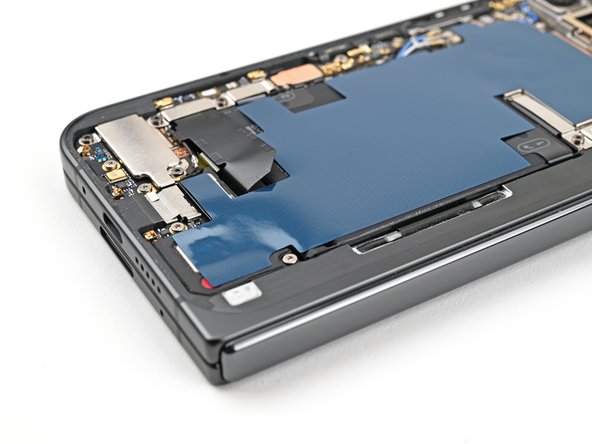
– Keep on peeling that graphite sheet off the logic board to break free from the last bits of adhesive holding it down!
Step 33

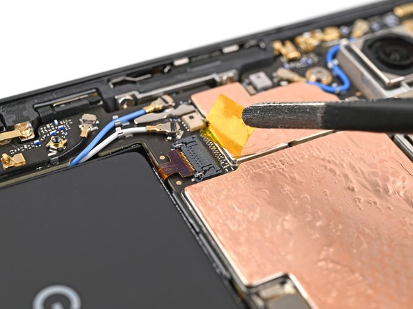
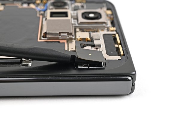
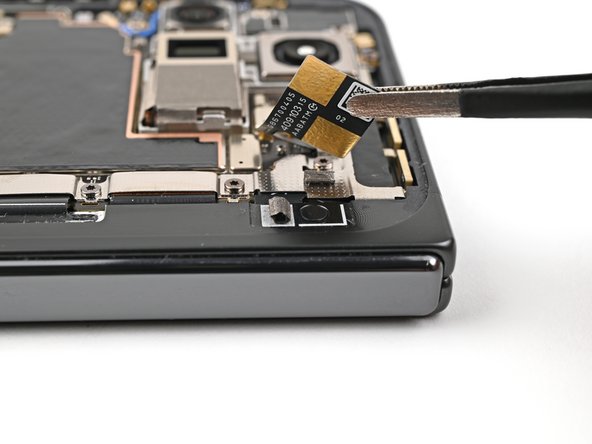
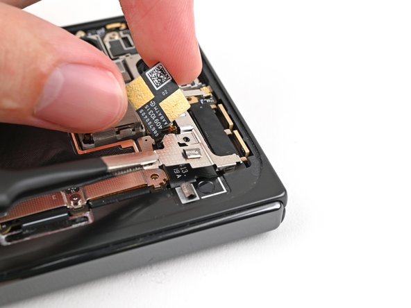
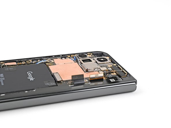
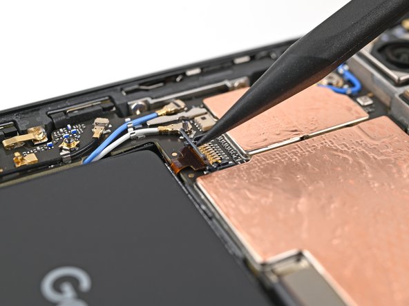
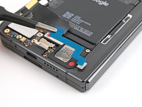
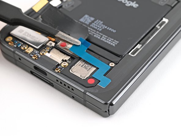
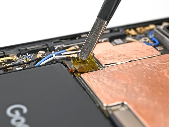
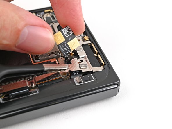
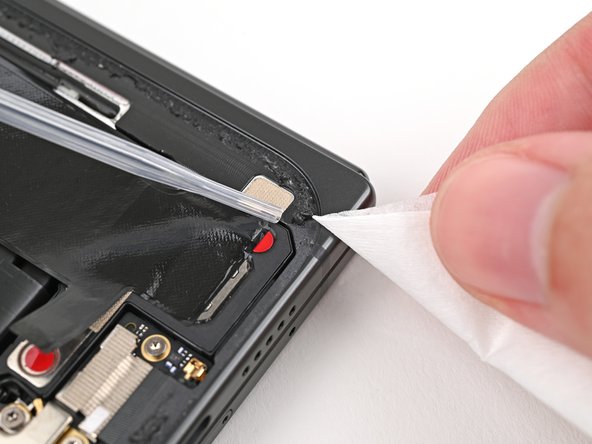
– Grab those tweezers or just use your trusty fingers to gently peel away the yellow tape from the ZIF connector on the side button cable. It’s like unwrapping a little present!
– Once you’ve got that tape off, set it aside for now. You’ll want it ready to go when it’s time to put everything back together.


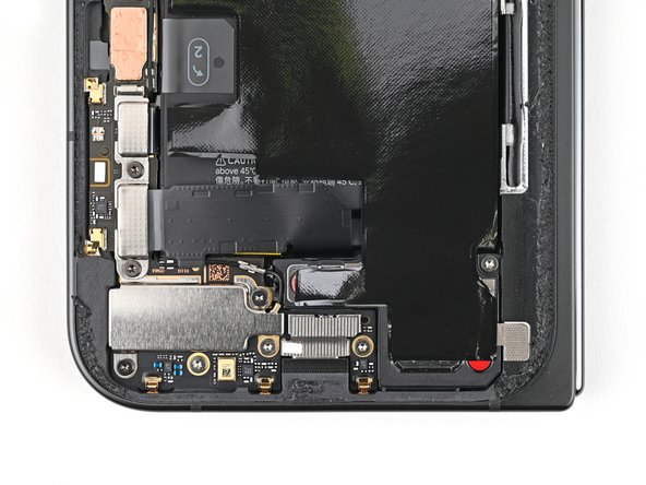
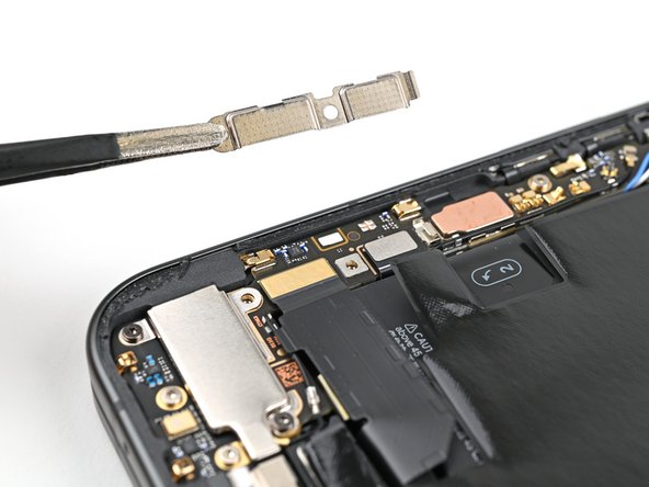
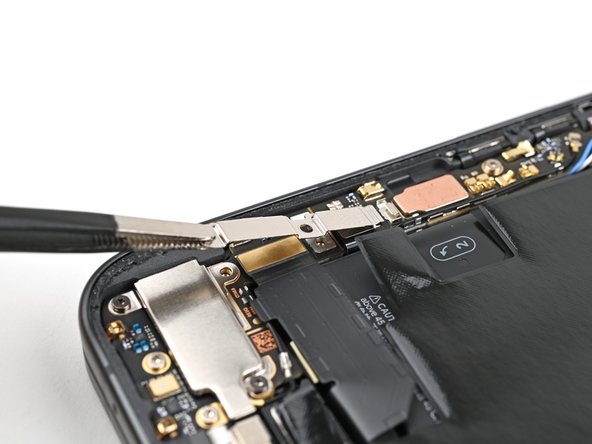
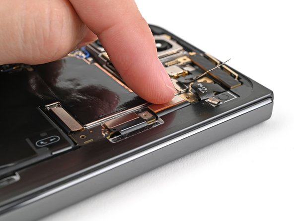
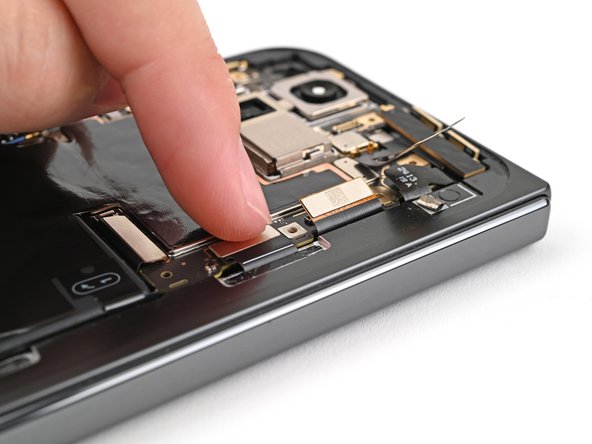
Step 36

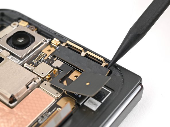
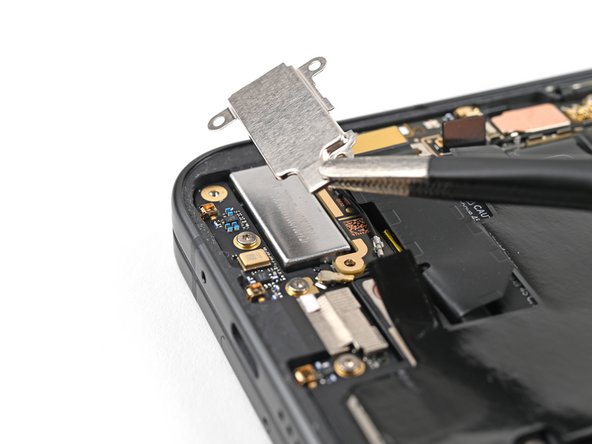
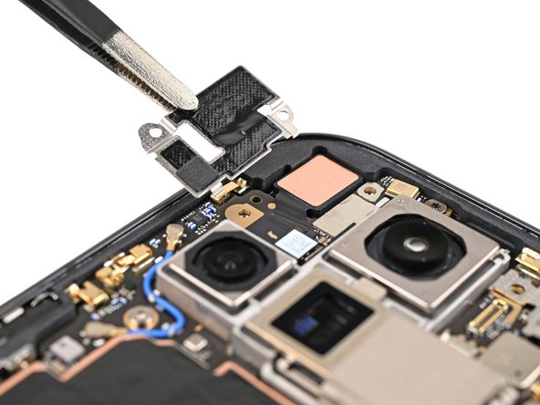
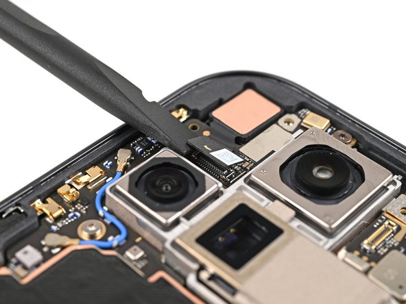
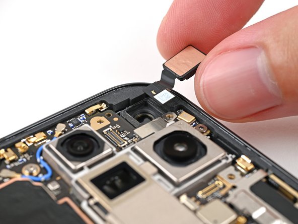
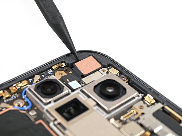
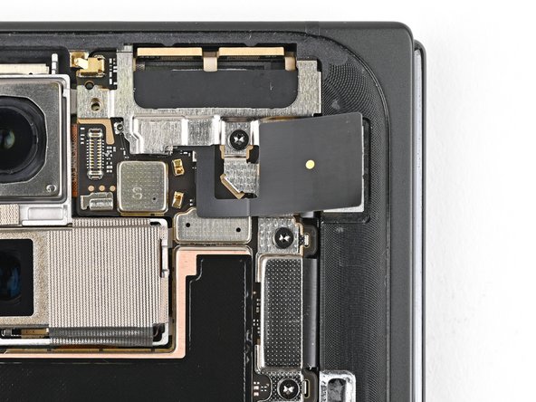
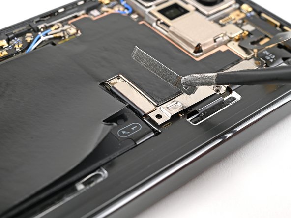
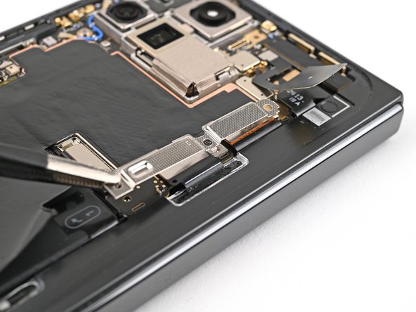
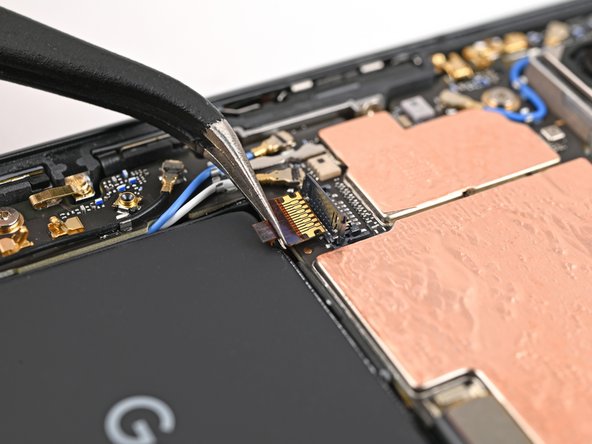
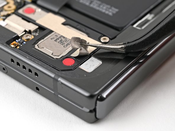
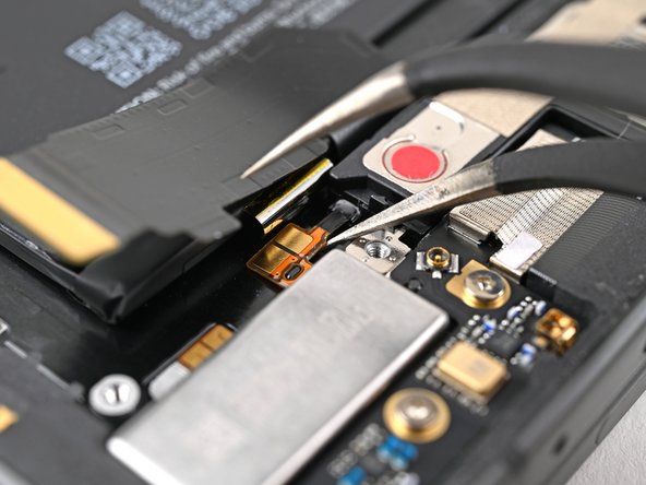
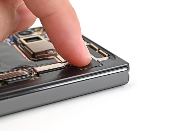
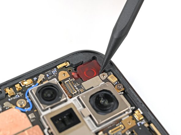
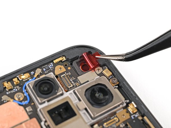
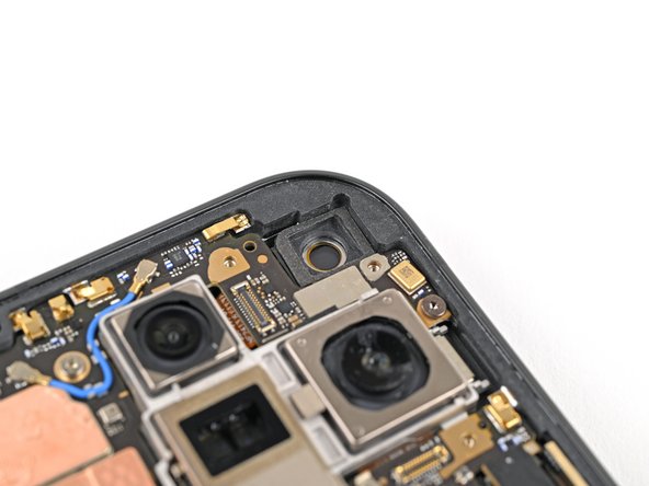
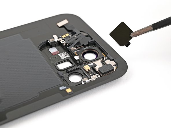
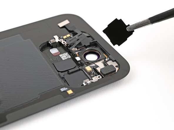
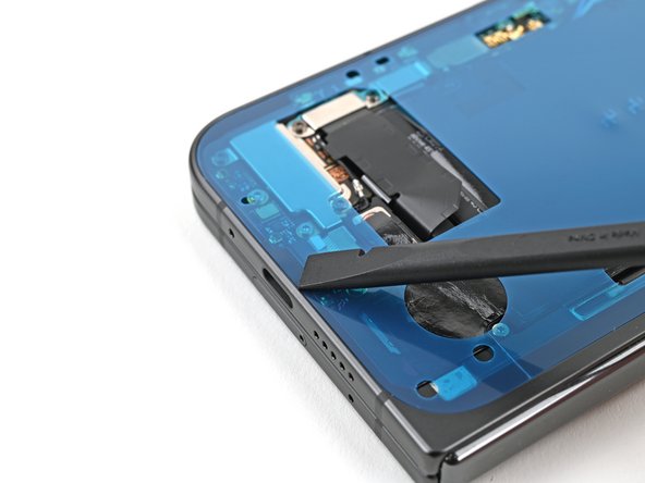
Hold on to your hats, this is where it gets interesting! The 5G mmWave antenna is attached to the frame using a thermal pad, which gives it a little extra grip. Don’t worry, it’s not glued down permanently, so we can gently remove it.
– Gently nudge the 5G mmWave antenna up from the frame using the spudger’s tip, making sure to separate it from that cozy thermal pad below.
Tools Used
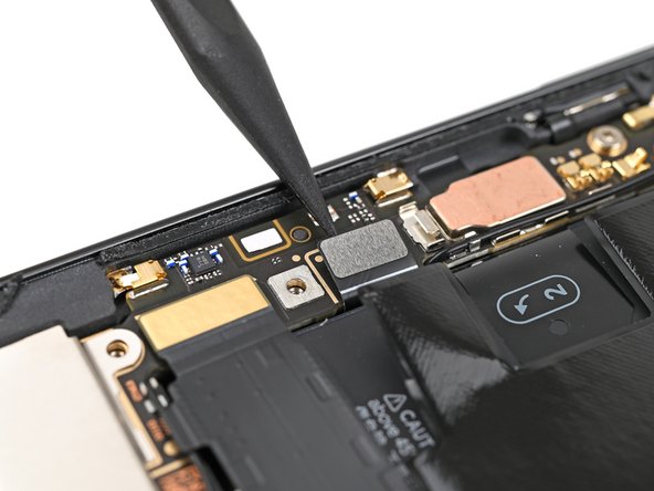
Step 37

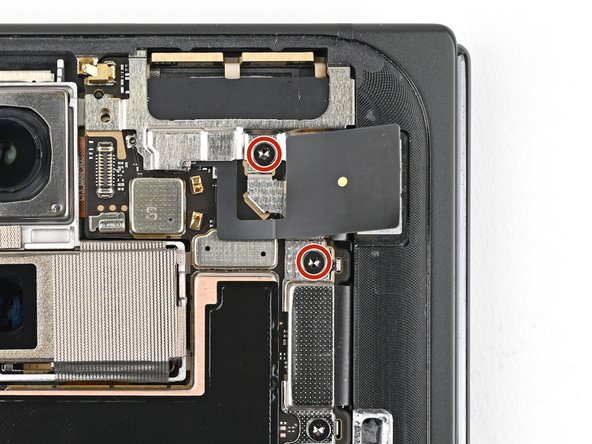
– Grab your trusty Torx Plus 3IP driver and let’s get to work! Start by unscrewing the three screws that are holding the logic board in place:
– One screw that’s 2.2 mm long – it’s the little guy!
– And two screws that are 2.6 mm long – a bit taller, but still friendly!
Step 38
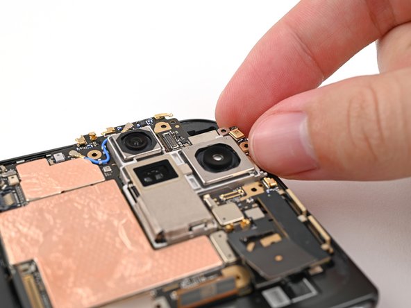

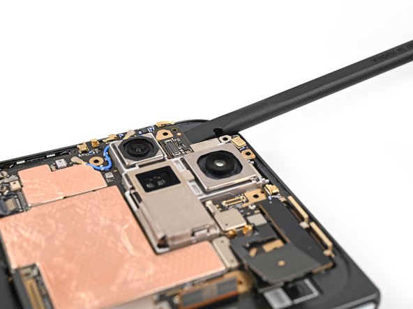
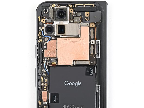
You might notice a bit of a tug there, as the logic board is snugly stuck to the frame with thermal paste. Just take it slow and steady!
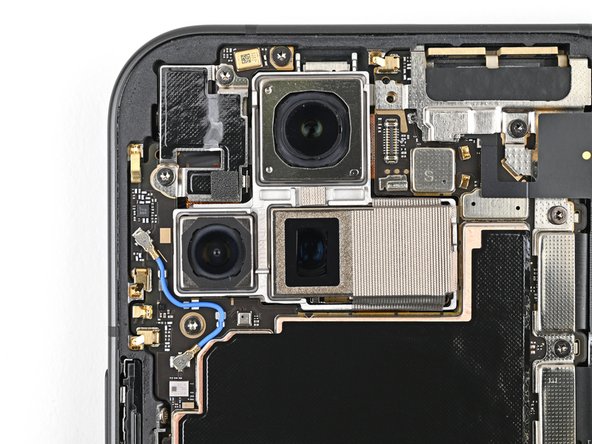
– Slip the flat end of a spudger underneath the top left corner of the logic board, right by the inner front camera cutout.
– Gently pry up the logic board just enough so you can grab the top edge with your fingers.
Tools Used
Step 39
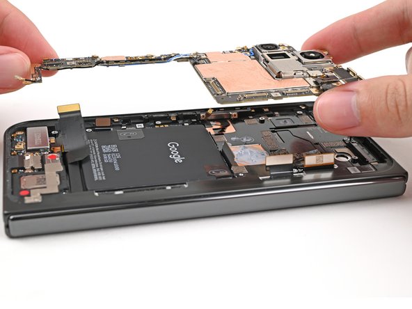
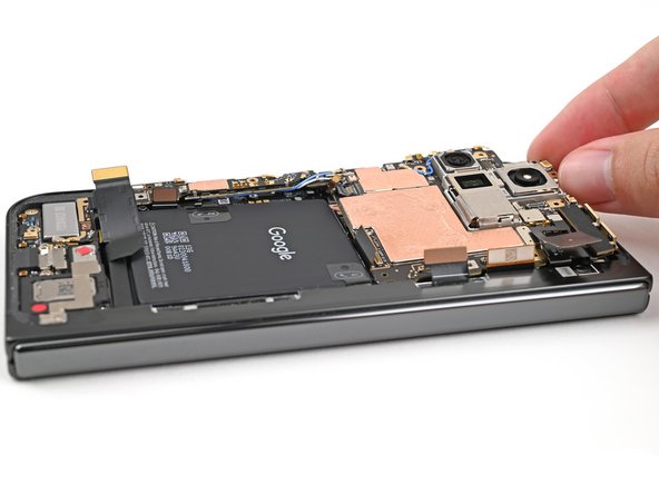
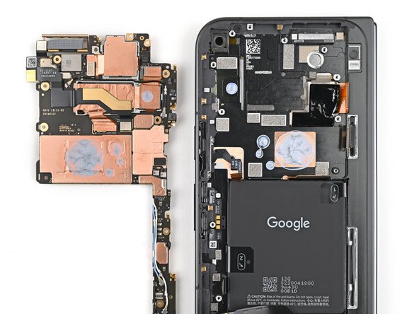
– Gently lift the logic board out of its cozy frame and set it free!
– Flip the logic board over and place it down on a nice, clean surface—it’s time for some TLC.
Step 40
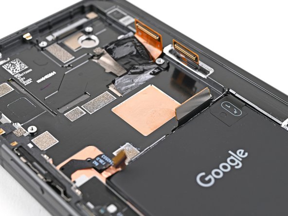
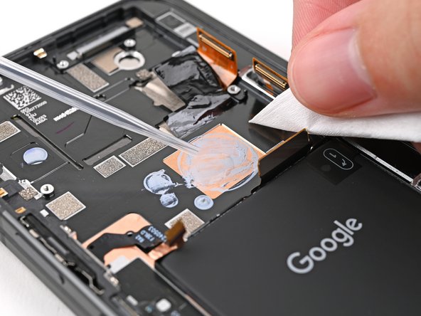

– Grab your spudger and gently scrape off the chunky bits of old thermal paste from the frame—think of it as peeling off a sticker.
– Dab a bit of high-strength isopropyl alcohol (90% or more) on any stubborn paste remnants—it’s like magic eraser juice.
– Polish it off with a coffee filter or lint-free cloth, leaving it squeaky clean and ready for action. If you’re stuck, you can always schedule a repair.
Tools Used
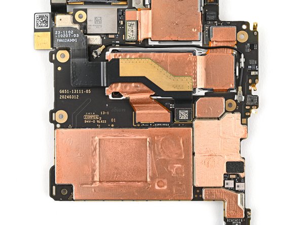
Step 41

Be gentle with the logic board while you’re giving it a cleaning! A light touch helps avoid bending those little metal springs or giving the rear camera assembly an unwanted smudge. You’re doing great!
– Don’t forget to give the bottom of the logic board some love too! Just like you did before, repeat that thermal paste cleaning procedure and make it shine.


Step 43

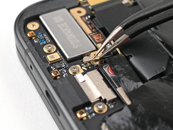
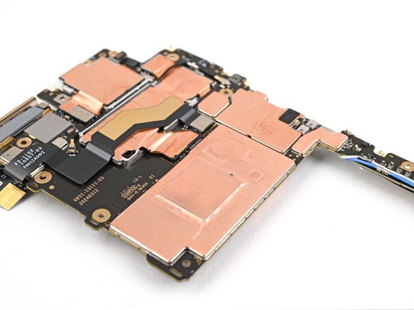
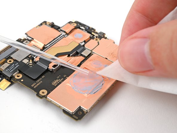
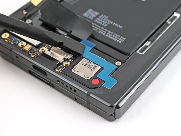
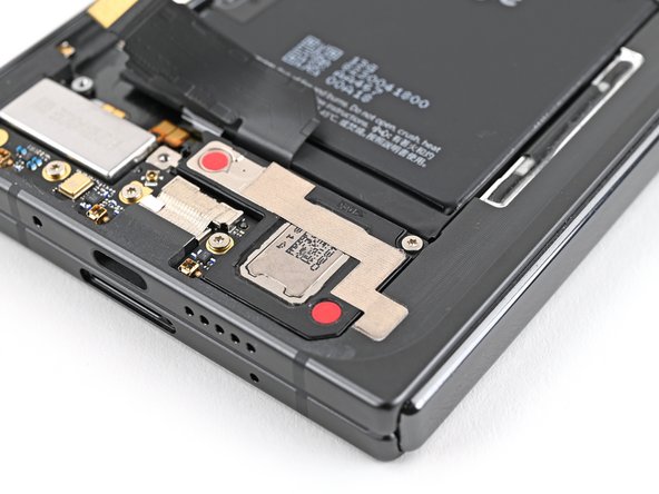
Be a smart cookie and avoid stabbing the battery—better safe than hazmat hazmat and spontaneous combustion!
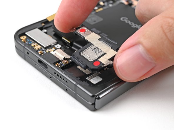
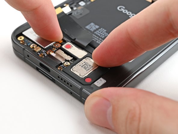
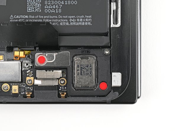
– Gently slide one arm of your trusty angled tweezers underneath the contact pad that’s cozy with the loudspeaker.
– Carefully lift the contact pad to peel away the adhesive that’s holding it snugly to the frame.
Tools Used
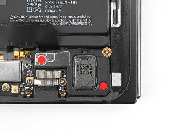
Step 44

– Let’s work together to remove the 2.6mm screw secured to the loudspeaker using a Torx Plus 3IP driver. You’re rocking this repair guide! Stay on this groove, and it’s gonna be smooth sailing from here. Just like an assembly line, every step you complete brings you closer to fixing your device. Feel the breeze of success ahead, it’s right within your grasp! If you need help, you can always schedule a repair to make your journey more enjoyable. Don’t forget to give yourself a pat on the back once you’re done – you earned it!

Step 46

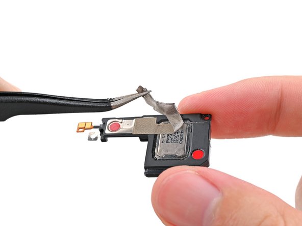
– Gently lift the top edge of the loudspeaker with your fingers and ease it out of the frame’s snug little spot.
– Now, go ahead and take out the loudspeaker!
Step 47

– Awesome job on getting everything apart! Now, let’s dive into the fun part—putting your device back together. Follow these steps and you’ll have it all back in one piece in no time!
Step 48

Alright, the next six steps are all about giving your loudspeaker a little TLC. We’re gonna be replacing the fabric on the bottom and giving the cable a fresh coat of adhesive. If you’re lucky and everything’s still looking good, feel free to skip ahead! But hey, if you need help with anything, you can always schedule a repair.
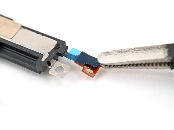
Step 49
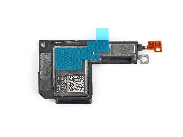

Check out the second picture to see how things should look!
– Get that bottom loudspeaker conductive fabric and line it up just right on the underside of the loudspeaker. You’ve got this!
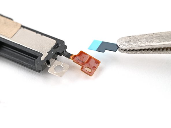
Step 50

– Peel the conductive fabric away from its clear and colorful liners, then gently place it right over its designated spot on the loudspeaker.


Step 55

– Hold the cable down, then gently slide the speaker into its place at an angle. Press it down until it’s flush with the frame. You got this!
Step 56

– Hold that loudspeaker steady, champ! Now, grab your trusty Torx Plus 3IP driver and snuggle that 2.6 mm‑long screw right into place. You’re practically done! If you need help, you can always schedule a repair.
Step 57

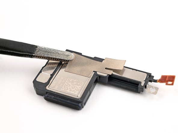
Alright, champ! Let’s give your speaker’s fabric a fresh look! The next four steps are all about replacing the fabric on top of your speaker. But hey, if that fabric is still rockin’ and rollin’, you can skip these steps and move on to the next adventure! No sweat!
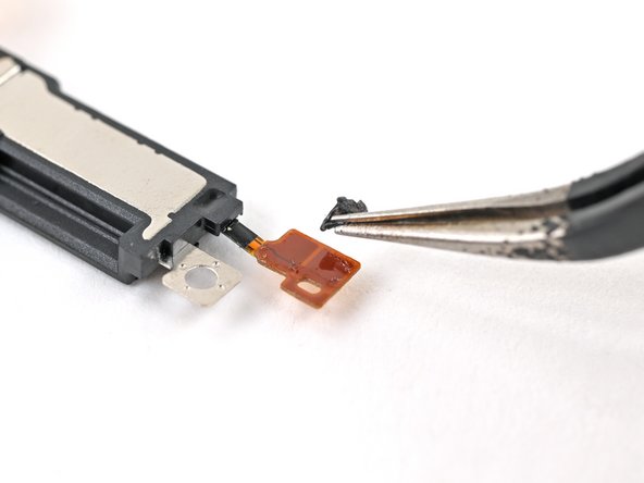
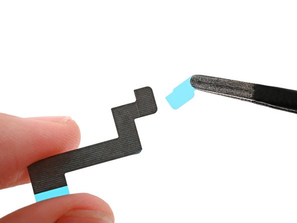
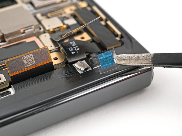
– Gently peel away the clear liner from the top loudspeaker’s conductive fabric. It’s like unwrapping a present!
– Carefully remove the small colored liner that’s hiding the rounded corner of the fabric. You’re doing great!


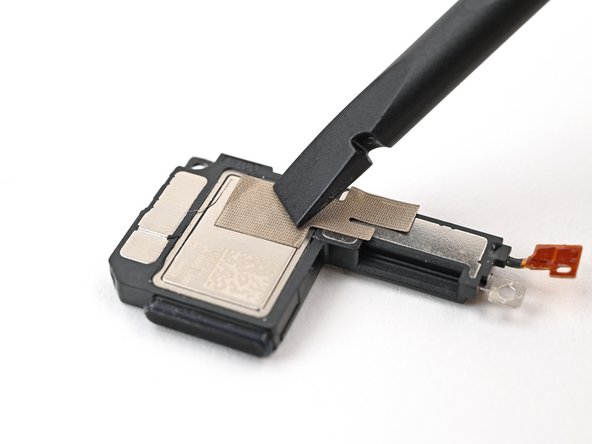
Step 60

– Gently peel away the big, colorful liner from the conductive fabric. You’re doing great!
Step 61
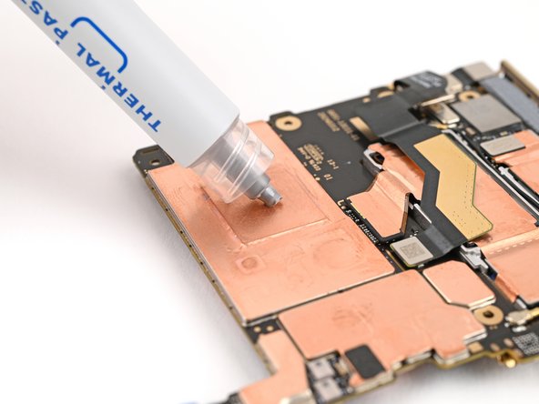

– Squeeze out tiny dots of thermal paste (five in total) onto the motherboard, making sure to place them in the same spots where the old thermal paste used to hang out.
Step 62


– Gently slide the logic board back into its cozy spot in the frame, ensuring that no cables get caught underneath. You’ve got this!
Step 63


– Grab your trusty Torx Plus 3IP driver and let’s get those screws in place to keep the logic board snug as a bug:
– One screw that’s 2.2 mm long
– And two screws that are 2.6 mm long
Step 64

– Grab those angled tweezers and gently nudge the side button cable back into its cozy little slot. You’ve got this!
Tools Used
Step 65

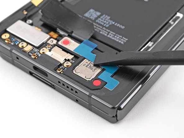
– Gently flip down the locking tab and give it a soft press until you hear that satisfying click! You’re doing great—keep it up!
Step 66

– Stick that sunny yellow tape right over the ZIF connector and its cable, ensuring everything stays snug and secure!
Step 67

– Time to get sticky! Peel back the clear liner off your replacement graphite sheet, revealing the awesome adhesive on the upper half.
– Line up the upper half of the graphite sheet perfectly over the logic board. Once it’s in place, gently lay it down.
Step 68

– Now, give that graphite sheet a little love! Gently press down on the upper half of the sheet and make sure it’s snuggled up nicely against the logic board.
Step 69

– Peel off the blue liner from the bottom of the graphite sheet to reveal the sticky goodness underneath.
Step 70

– Gently glide your finger from the center of the graphite sheet over to the sticky spot on the loudspeaker. This will help smooth out the graphite sheet and make sure it sticks nicely!
Step 71

– Grab that pull tab at the top of the graphite sheet and gently peel away the remaining liner. You’ve got this!
Step 72

– Now, let’s reconnect those cables! Give the inner display cable and the top and bottom interconnect cables a gentle press to make sure they’re snug.
Step 73

– Slide that inner display cable bracket clip back into its cozy spot on the logic board and make sure those screw holes are all lined up nicely.
Step 74

– Grab your Torx Plus 3IP driver and secure the inner display cable bracket with the 3.0 mm-long screw. Easy peasy!
Step 75

– Slide that bottom interconnect bracket clip back into its cozy spot in the frame and make sure the screw hole is lined up just right!
Step 76

– Time to get rad and install that 3.0 mm-long screw with a Torx Plus 3IP driver – you’re a wrecking ball that’s bout to put that interconnect cable bracket where it belongs!
Step 77

– Keep that ultra wideband antenna safely out of the way for now! Slide the ultra wideband bracket clip back into its cozy spot in the frame and make sure those screw holes are lined up nicely. Let’s get this back together!
Step 78


– Grab your trusty Torx Plus 3IP driver and let’s get those two 3.0 mm-long screws in place to secure the ultra wideband bracket. You’ve got this!
Step 79

If the adhesive on your ultra wideband bracket still has some stickiness to it, feel free to breeze past this step!
– First up, let’s get rid of that old adhesive and foam stuck on the ultra wideband bracket and beneath the antenna. Out with the old!
– Next, it’s time to give your bracket and frame some love with fresh adhesive and foam. They deserve it!
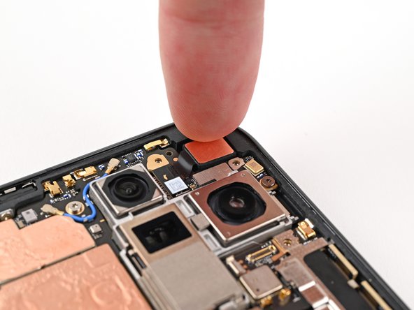
– Now, gently press the ultra wideband antenna back onto the frame and re-adhere it. You’ve got this!
Step 80

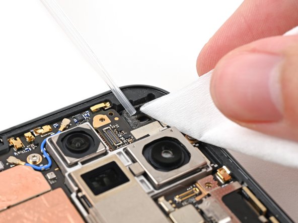
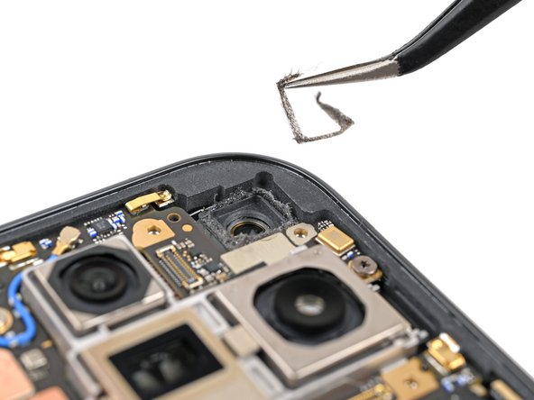
– Grab some tweezers or just use your fingers to gently peel away that old adhesive foam from the inner front camera cutout. It’s like removing a sticker—just a bit more satisfying!
– Now, let’s tidy up! Take some isopropyl alcohol (at least 90% or higher) and a coffee filter or a lint-free cloth. Give that area a good wipe to get rid of any leftover adhesive residue. Your device will thank you!
Step 81

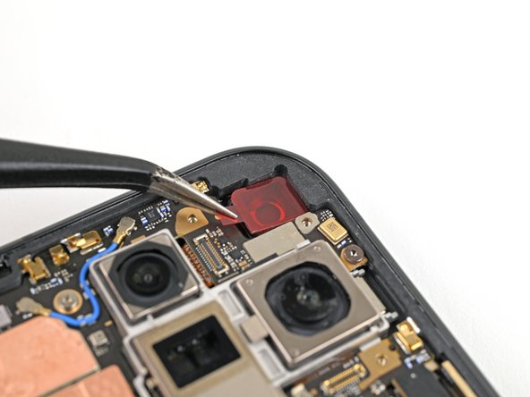
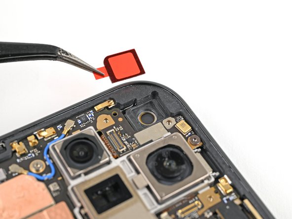
– Carefully peel off the clear liner from the replacement inner front camera adhesive foam to reveal the sticky side waiting for action!
– Line up that adhesive foam perfectly over the cutout in the frame, making sure the pull tab is pointing down towards the bottom of your phone.
– Gently place the adhesive right into the cutout and let it do its job.

Step 83

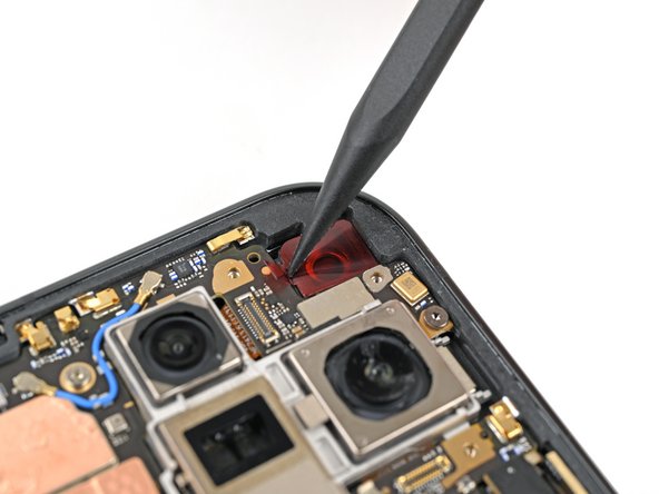
– Grab your trusty tweezers or just use your fingers to gently peel away that colorful liner and reveal the sticky goodness hiding underneath.
Step 84

– While keeping the inner front camera hovering just above its cozy little cutout, reconnect its press connector with a gentle touch.
– Nestle the inner front camera into its cutout and give it a little press to make sure it sticks snugly to the adhesive.
Step 85

– Carefully tuck the inner front camera bracket clip back into its cozy spot on the logic board and make sure those screw holes are all lined up perfectly.
Step 86


– Grab your trusty Torx Plus 3IP driver and let’s get those two 2.6 mm-long screws snugly holding the inner front camera bracket in place. You’ve got this!

Step 88

– Carefully set the vibrator bracket onto the logic board, making sure to line up those screw holes just right!
Step 89

– Grab your trusty Torx Plus 3IP driver and secure the two 3.0 mm-long screws that hold the vibrator bracket in place. You’ve got this!
Step 90

– Reconnect the USB-C port board cable by firmly pressing the connector back in place. You’re almost there!
Step 91

– Lend a helping hand to your device’s base battery by reconnecting the press connector! It’s about to feel the love. Ready, set, mate!
Step 92

– Slide that base battery bracket clip back into its cozy spot on the logic board, making sure those screw holes are perfectly lined up. You’ve got this!
Step 93


– Grab your Torx Plus 3IP driver and pop in the two 3.0 mm screws to secure that base battery bracket. Keep up the great work!
Step 94

– Grab a spudger or just your trusty fingers to gently peel away that old back cover adhesive.
– Next up, take some isopropyl alcohol (make sure it’s over 90%) and a coffee filter or a microfiber cloth to wipe away any leftover sticky residue.
Tools Used
Step 95

Got a shiny new back cover ready to go? Awesome! Just follow the next couple of steps. If not, feel free to skip ahead.
– Grab your trusty tweezers or just your fingers, and gently lift out the three rear camera liners snugly tucked inside your shiny new back cover. You’ve got this!
Step 96

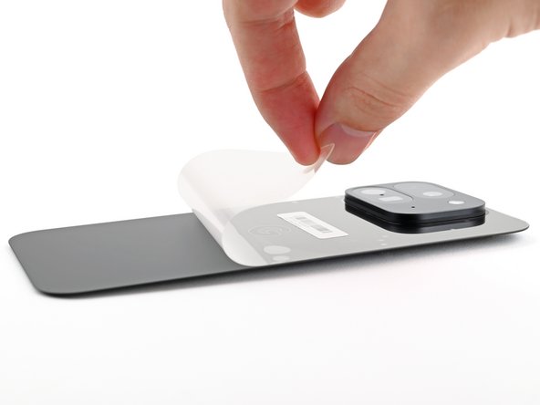
– Gently peel away the last bits of the clear liners clinging to the outside of the back cover. You’ve got this!

Step 98

Take your time on this step! It’s a bit tricky and you wouldn’t want to accidentally place that adhesive in the wrong area. Just breathe, go slow, and you’ll nail it!
– Get ready to rock and roll, let’s pry open that tightly guarded case! Unveil the first half of your snazzy new adhesive and keep it close, like a secret agent. Don’t lose that magical teeny weeny strip, okay? Okay! 🙌 Then, gently place it on the frame like a delicate jigsaw puzzle piece. The corners should be your best friends here! 👌

Step 100

– As you peel away the final bits of that clear liner, gently position the rest of the adhesive around the edge of your phone. You’ve got this!

Step 102

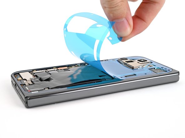
– Grab your trusty spudger and gently lift the segmented tab located in the bottom right corner of that big blue liner. You’ve got this!
– Once you’ve lifted the tab, peel away the large blue liner to reveal the hidden secondary liner underneath. Keep going, you’re doing great!
Tools Used
Step 103

No need to force things, my friend! If you’re struggling, just wiggle the connector a bit and try again. You got this!
– While keeping the back cover steady or propped up, go ahead and reconnect that back cover cable.
Step 104

– Now, pop that top bracket clip back into its cozy little spot on the logic board. Make sure the screw hole is lined up, and you’re good to go!
Step 105

– Alright, buddy, let’s get this thing buttoned up! Grab your trusty Torx Plus 3IP driver and give that 3.0 mm‑long screw a nice snug fit. It’s securing the top bracket, so make sure it’s in there good!


Step 108

– Line up the top edge of the back cover with the frame and give it a little press to make it stick. You’re almost there!
Step 109

For an extra strong seal, you can give the edges of the back cover a little warmth with a hair dryer or heat gun. Just a quick zap should do the trick!
– High five for finishing your repair journey!
– Make sure to recycle your e-waste responsibly at an R2 or e-Stewards certified recycler.
– If things didn’t go as smoothly as expected, don’t sweat it! A little troubleshooting might do the trick, and if you’re still in a pickle, feel free to reach out for support.
– Change your mind? No worries! Just let us know you didn’t wrap this up.
–
Success!