How To Replace iBook G3 Clamshell Charger Board Step-by-Step Guide
Duration: 45 minutes
Steps: 35 Steps
Hey there, repair champs! Just a little heads-up: if you find yourself scratching your head or feeling a bit lost, don’t worry! It’s totally okay to ask for a helping hand. If you need assistance, you can always schedule a repair. We’ve got your back!
Charge up that battery and give it a happy little connection to the logic board. You got this!


Step 2

– Give those keyboard release tabs a little tug towards you and gently lift up on the keyboard until it pops away. Just a heads up, the keyboard ribbon is still connected to the logic board, so you won’t be able to fully remove the keyboard just yet.
– If the keyboard is feeling stubborn, grab a small flathead screwdriver and turn the keyboard locking screw (that’s the one hanging out between the F4 and F5 keys) a quick 180 degrees in either direction, then give it another go.
– Now, swing the keyboard away from the screen and rest it face-down on the trackpad area like it’s taking a little nap.
Step 3

If your computer doesn’t sport an airport card, feel free to breeze past the next couple of steps!
– Grab that clear plastic tab on the airport card and gently lift it up while pulling it toward the display. You’ve got this!
Step 4

– Grab the airport card with one hand, and with your other hand, gently detach the antenna cable. You’ve got this!
Step 5

– Unscrew those two Phillips screws holding down the RAM shield like a pro!
Step 6

– Grab hold of the metal bracket sitting on top of the RAM shield and give it a gentle tug upwards to pop that shield off.

Step 8

– Grab a straightened paperclip and give that CD-ROM tray a little nudge to pop it out manually. You’ve got this!
Step 9

– Flip that computer over so the bottom is ready for action!
– Now, let’s get those Torx screws out of the way:
– You’ll need to tackle four short T8 Torx screws hanging out near the battery compartment.
– And don’t forget the two long T8 Torx screws waiting by the hinges.
Step 10

– Gently slide the CD-ROM drive tray out just a bit. No need to rush, you’re doing great!
– Unscrew the shiny Phillips screw from the plastic casing, and remember, every little step counts!
Step 11

– Flip your computer over so we can get started on this adventure.
– Unscrew those three Phillips screws like a pro!
Step 12

Here’s a handy diagram showing the trackpad ribbon clamp connector that you’ll be disconnecting in the next step. Let’s get to it!
– 1) Grab that locking bar on either side with your trusty fingernails and give it a gentle pull upwards just a smidge (around 1/16″ or 2 mm). You’ve got this!
– 2) Once you’ve freed the locking bar, smoothly slide the cable right out of the connector. Easy peasy!

Step 14

Be careful not to raise the upper case too high before disconnecting that audio cable first!
– Gently nudge the rim of the lower case outwards while lifting the upper case, making sure to hold onto it just to the left of the optical drive.
– Now, let’s do a little dance on the upper left corner of the upper case; grab the bottom left corner and give it a gentle lift!
Step 15

– Unplug the audio cable and give it a little wave goodbye!
Step 16

You might be worried about damaging your upper case, but fear not! The tabs that hold the upper and lower cases together are pretty sturdy. Just apply consistent pressure and gently lift the upper case up and away from the screen until it releases. You’ve got this!
Step 17

– Got a stubborn optical drive? No worries! Grab a straightened paperclip and give it a gentle poke to pop it open.
– Next up, let’s tackle that pesky 5 mm standoff. Time to remove it!

Step 19

Got a CD or some other sneaky object stuck in your optical drive? No worries, we’ve got just the guide you need to get it back in action! Check out our optical drive repair guide.
– Gently lift the optical drive while playfully pushing each of those little plastic tabs towards the screen, one by one, to release one side of the drive.
– Once you’ve freed up that side, give the optical drive a little lift and slide it out and away from the screen like a pro.
– When it’s time to put the optical drive back, just make sure the drive tray is extended enough to sneak under the lower casing rim.
Step 20

– Let’s kick things off by taking out those Phillips screws!
– Next up, gently detach the EMI fingers.
– Now, grab that longer Phillips screw located in the middle-rear of the modem shield and remove it.
– Time to tackle the three identical Phillips screws—two on either side of the EMI fingers and one hanging out on the right side of the modem shield.
– Lastly, let’s not forget about the larger Phillips screw that keeps those EMI fingers snug on the modem board.
Step 21

– Gently lift the modem shield off the metal frame, starting from the right front and gracefully gliding to the left. You’ve got this!
Step 22

– Unscrew the Phillips screw on the left side of the modem with a friendly twist.
– Gently pry up the right side of the modem like you’re lifting the lid on a treasure chest.
Step 23

– Gently pull the modem out just a bit and unplug the cable located on the left side.
Step 24

– Unscrew the Phillips screw from the left hinge – think of it as giving your device a little makeover!
– Gently peel back the airport cable from underneath the cheerful yellow tape. It’s like unwrapping a gift for your gadget!
Step 25

– Unplug the big display data cable from the logic board and gently guide it out from the plastic and metal tabs. You’ve got this!

Step 27

– Take out those three tiny Phillips screws from the clutch cover and let the magic begin!
Step 28

– Alright, here we go! With one hand, gently support the display while you unscrew that last Phillips screw from the right hinge. Just remember to push the display down lightly to keep the screw happy and stress-free.
– Time to say goodbye to the display assembly! Give it a gentle removal.
– Now, when you’re putting the display assembly back in place, ensure that the clutch cover slides over those cheeky white plastic tabs sticking out from the rear underside of the laptop. They like to be tucked in nicely!
Step 29

– Take out those two little Phillips screws holding down the RJ-11 board. You’ve got this!
Step 30

– Gently nudge the lower case rim outwards and carefully lift the RJ-11 board out of your device.
Step 31

– Carefully untangle the speaker cable from the metal frame and unplug it from the logic board. You’ve got this!
Step 32

– Ready to dive in? First up, let’s tackle those six screws! (If your iBook is a Firewire-less wonder, don’t worry – the orange-circled screw won’t be there to greet you.)
– You’ll find two short, flat-headed Phillips screws hanging out near the battery compartment. Say hello to them!
– Next, keep an eye out for one short, round-headed Phillips screw chillin’ near the speaker cable connector. (Just a heads up – some models have it, and some don’t, especially the older ones.)
– Now, locate the one short, flat-headed Phillips screw nestled between the ethernet and USB ports.
– Don’t forget about the one short, flat-headed Phillips screw to the left of that hole-y (yes, we see what you did there) area.
– Finally, there’s a long, round-headed Phillips screw waiting for you near the power receptacle. Time to give it some attention!
Step 33

– Gently lift the right side of the EMI shield and slide it out of the computer with a smile!

Step 35

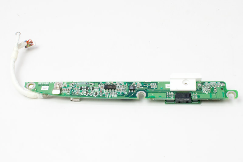
– First up, gently unplug that charger board cable from the logic board. No need to rush, take your time!
– Next, carefully lift out the charger board. You’re doing great!