How to Replace Interconnect Cables in Samsung Galaxy S21+
Duration: 45 minutes
Steps: 20 Steps
Hey there! Time to tackle the repair for your awesome SM-G996B/DS device. Let’s get to it and have your device up and running in no time. Remember, if you need help, you can always schedule a repair.
Ready to swap out those interconnect cables on your Samsung Galaxy S21 Plus? You’ve come to the right place! We’ll guide you through this process using the SM-G996B/DS (international) model as our example. Just a heads up, if you’re working with other models, you might find an extra antenna cable hanging out at the edge of the midframe. Now, when it’s time to put everything back together, keep in mind that skipping the adhesive seals may let your device work just fine, but it might lose a bit of that sweet water resistance. So, grab some replacement adhesive to keep everything snug and secure during reassembly. If you need help, you can always schedule a repair.
Step 1

– Grab your trusty iOpener and place it on the back cover for a cozy three minutes. This will help loosen up the adhesive hiding underneath, making your repair journey a little smoother.
Tools Used

Step 2


– Let’s channel our inner Transformer and attach a sweet suction handle to the bottom edge of the back cover – keep it close to the edge!
– Now, give that back cover a good ol’ lift with the suction handle. This’ll create a sweet little gap between the back cover and the frame.
– Time for the opening pick to shine. Slide it into the gap you just made.
– Work your way down to the bottom left corner. Time to slice up that adhesive.
– Leave that opening pick in place, like a tiny little bridge stopper, so the adhesive stays put.
Tools Used

Step 3


– Got it! Time to add a second opening pick at the bottom of your phone.
– Slide that pick over to the bottom right corner and cut through that adhesive like a pro!
– Keep those picks where they are to make sure that adhesive doesn’t get any funny ideas about sealing back up on you.
Step 4


Looking cool can be tough when the adhesive gets tough. Give it a quick warm-up with your iOpener, and you’ll be back to cutting in no time!
– Pop a third opening pick into the bottom right corner of your phone, like a pro!
– Gently glide that pick along the right edge, slicing through the adhesive like a hot knife through butter.
– Leave the pick snug in the top right corner; it’s doing the important job of keeping the adhesive from sealing back up. Way to go!
Tools Used
Step 5


When you’re carefully slicing near the camera assembly, just slide in the tip of that opening pick (about 4-5 mm) to keep your precious camera safe from damage or smudges!
– Okay, phone repair experts! Let’s get poppin’ with the top right corner. Work that opening pick like it’s hot and slide it along the top edge. And when you’re done, good news: you’ve got a trusty opening pick ready and waiting in the corner to keep that adhesive from being a troublemaker. Rock on!
Step 6


– Slide a fifth opening pick right under the bottom left corner. It’s like giving your device a gentle nudge!
– Now, glide that pick along the left edge of the back cover to cut through the rest of the adhesive. You’re almost there!
Step 7


– Get ready to unleash your inner repair champ by removing that sleek back cover.
– Remember, during the reassembly dance, you’re the lead and those components are your backup dancers. Let’s hit all the right moves!
Step 8


Handle that battery with care! Poking or bending it could lead to some serious leaks of dangerous chemicals or even a thermal situation. Let’s keep it safe and sound.
Watch out for that sneaky cable hiding under the charging coil! Take your time, and if your pick starts to snag, it’s a sign to pause and reassess. We’ve got this!
– Slide an opening pick under the left bottom corner of the NFC antenna and charging coil assembly. You’re doing great!
– Now, gently glide that opening pick along the bottom left edge of the assembly to gently detach it from the battery. Almost there!
Step 9

– Slide an opening pick gently underneath the lower edge of the NFC antenna and charging coil assembly. You’re on the right track!
– Carefully glide that opening pick along the base of the assembly to free it from the loudspeaker. You’re doing great!
Step 10


– Grab your trusty spudger and gently lift the charging coil connector straight up from its socket. You’re doing great!
Tools Used


Step 12

– Grab your trusty Phillips screwdriver and get ready to tackle those five 3.9 mm screws holding the NFC antenna and charging coil assembly in place. You’ve got this!
Step 13


– Grab a trusty pair of tweezers or just your fingers, and gently lift out that NFC antenna and charging coil assembly like you’re unwrapping a surprise gift!

Step 15

– Grab a Phillips screwdriver and tackle those six 3.9 mm-long screws holding the loudspeaker assembly in place. You’ve got this!
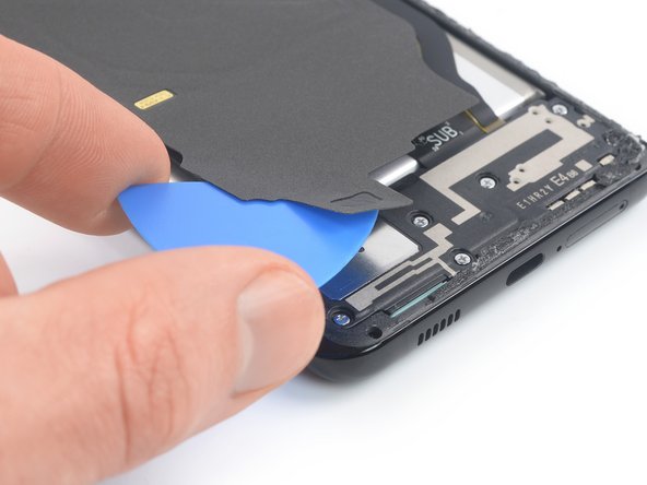
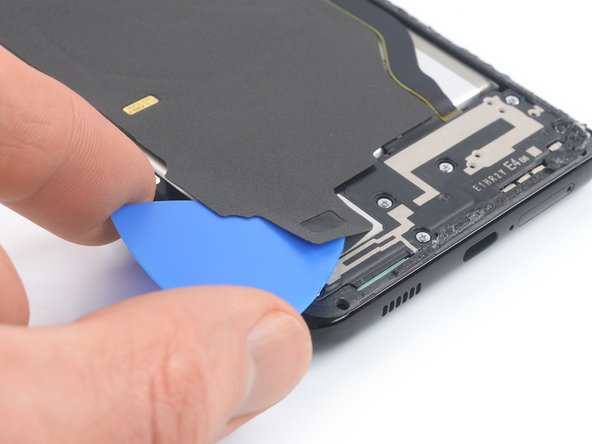
Step 16


– Slide an opening pick into the little gap between the top edge of the loudspeaker assembly and the midframe. Just a gentle nudge will do!
– Now, use that trusty opening pick to carefully lift the loudspeaker assembly by angling it downward. You’re doing great!
Step 17


– Gently take out the loudspeaker assembly.
– When you’re putting it all back together, don’t forget to use fresh adhesive where needed. A little cleaning with some isopropyl alcohol (>90%) will help the new glue stick like a champ!
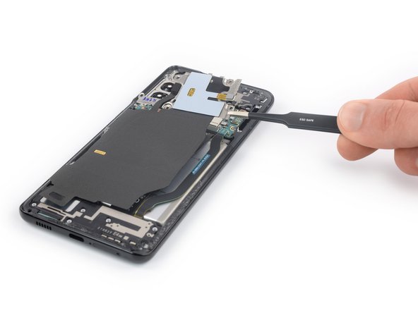
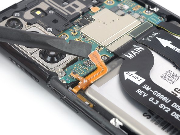
Step 18

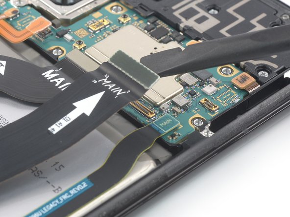
– Grab your trusty spudger and gently pry the upper connectors of the main and interconnect flex cables straight up from their sockets to disconnect them from the motherboard. You’ve got this!
Tools Used
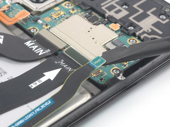
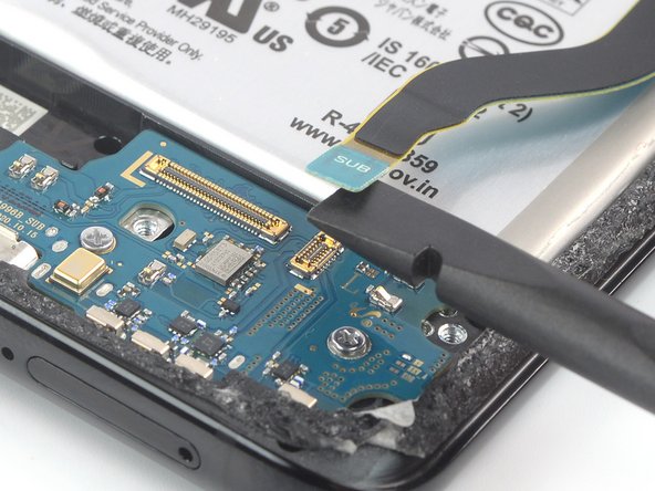
Step 19

– Get groovy with a spudger to disconnect the main flex cable from the daughterboard by prying its bottom connector straight up from its socket.
– Channel your inner zen master and use your fingers or a pair of tweezers to delicately remove the main flex cable.
Tools Used
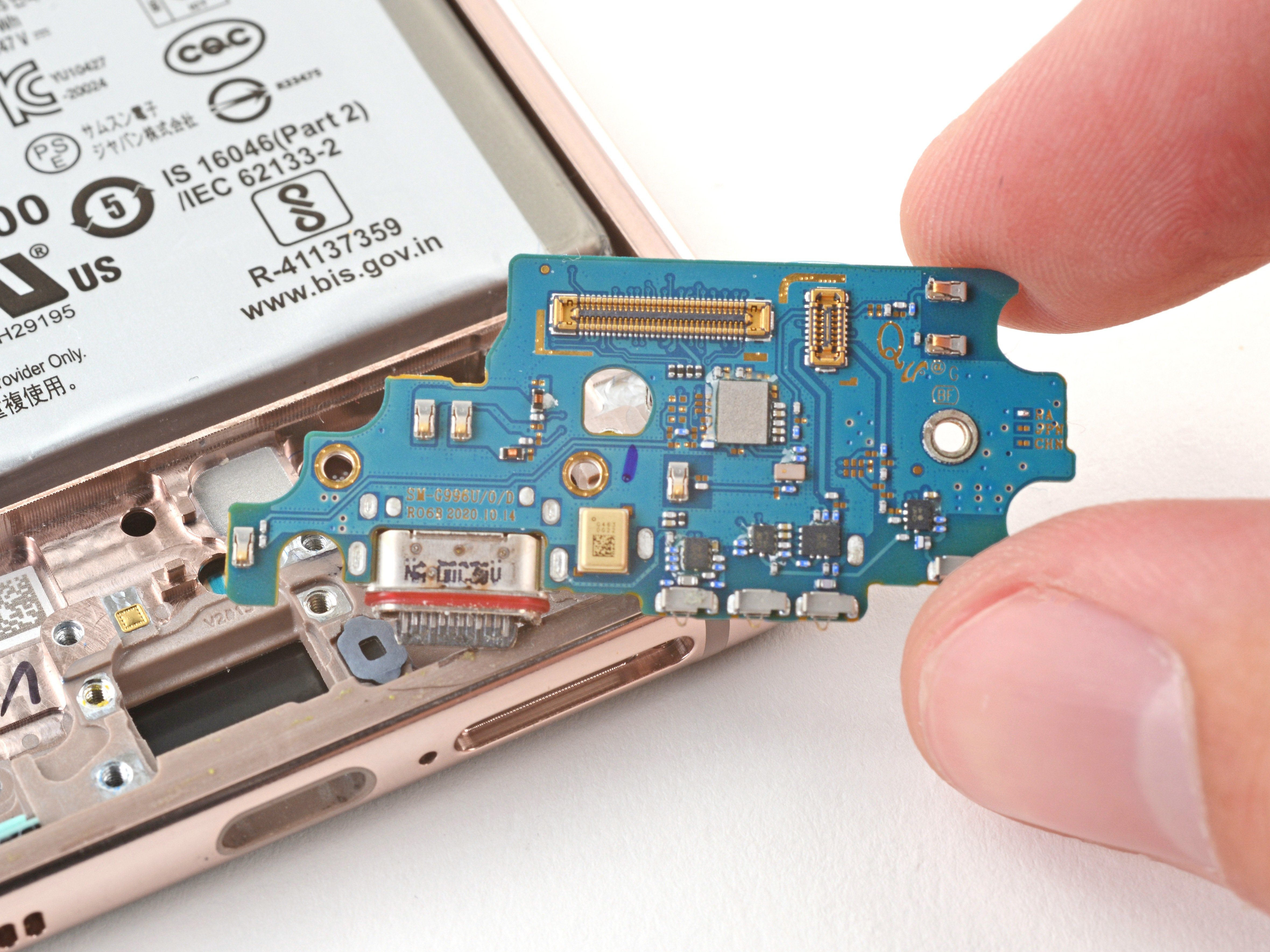
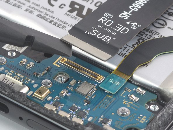
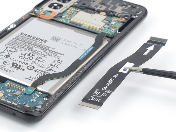
Step 20


– Ready to show that interconnect flex cable who’s boss? Grab a spudger and gently disconnect it from the daughterboard by prying its bottom connector straight up from its socket.
– Next, use your fingers or a pair of tweezers to gracefully remove the interconnect flex cable. You’ve got this!
Tools Used