How to Replace iPad 2 Wi-Fi EMC 2415 Volume and Power Button Cable
Duration: 45 minutes
Steps: 58 Steps
Heads up! Make sure to follow these steps carefully to avoid any hiccups. If you find yourself in a jam, don’t hesitate to reach out for help. You can always schedule a repair and we’ll get you sorted!
Get ready to tackle the replacement of the volume and power button cable assembly in your iPad 2 Wi-Fi EMC 2415! This nifty assembly also houses the sensor that senses the magnet in your Smart Cover. If you need help, you can always schedule a repair.
Step 1


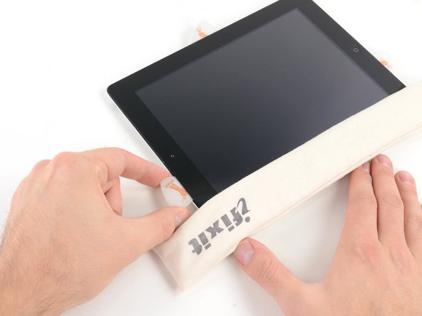
Before diving in, give your microwave a little TLC! Cleaning it up will ensure that any pesky residue doesn’t stick to your iOpener during the process. Let’s keep things tidy and smooth sailing!
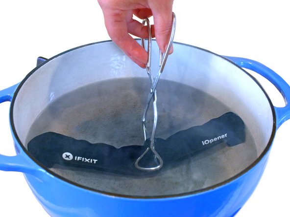
– Pop that iOpener right in the middle of the microwave and let it get nice and toasty!
Tools Used

Step 2

Keep an eye on that iOpener during your repair journey! If it gets too hot, it might just decide to pop like a balloon. Remember, no heating over 100˚C (212˚F) – we want it to help, not surprise us!
If the iOpener looks like it’s trying to become a pufferfish, steer clear! Safety first!
If the middle of the iOpener is still feeling like a hot potato, just hang tight and let it cool down a bit before you give it another round of heat. A well-heated iOpener should stay toasty for about 10 minutes.
– Warm up the iOpener for thirty seconds to get things rolling.
– As you work through the repair, keep that iOpener cozy by giving it a quick reheat in the microwave for another thirty seconds whenever it starts to cool down.
Tools Used
Step 3

Watch out! The iOpener gets super toasty, so handle it with care. An oven mitt can be your best friend here!
– Carefully take the iOpener out of the microwave, grabbing it by one of the flat ends to keep your fingers safe from the warm center.
Tools Used
Step 4

No microwave? No problem! Just pop that iOpener into some boiling water to get it nice and toasty.
– Grab a pot or pan and fill it with enough water to completely dunk that iOpener.
– Turn up the heat and bring the water to a rolling boil, then switch off the stove.
– Carefully drop the iOpener into the hot water for about 2-3 minutes, ensuring it’s fully submerged and getting cozy.
– Using tongs (safety first!), lift out the warm iOpener from the water.
– Give the iOpener a good towel dry—no one likes a soggy tool!
– Voila! Your iOpener is all set for action! If it needs a little more warmth, just repeat the boiling process and let it soak again for 2-3 minutes.
Tools Used
Step 5


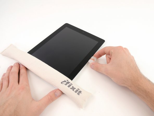
Put on your safety glasses to keep those peepers protected, and watch out for that LCD screen—it’s more delicate than it looks!
– If your display glass is cracked, let’s keep it from shattering all over the place and avoid any accidents while you work. A little tape can go a long way!
– Grab some clear packing tape and lay overlapping strips over your iPad’s display until it’s completely covered. It’s like giving your device a protective blanket!
– Do your best to stick with the rest of the guide as it unfolds. Just a heads up: once the glass starts to crack, it may continue to do its thing as you work. You might need to use a metal prying tool to carefully scoop out the glass bits.
Step 6

Hey there! Just a friendly reminder that while you’re tackling this repair, you might encounter some broken glass. It’s a good idea to rock a pair of safety glasses to shield your eyes from any unexpected flying bits. Stay safe and keep shining!
– Position the iOpener flat against the right edge of your iPad, making sure it’s snugly in place to create a solid connection between the iPad and the iOpener.
– Give the bag a little time to work its magic on the iPad—about 90 seconds should do the trick—before you start prying open that front panel.
Tools Used
Step 7


Getting that wedged tip of the opening tool snugly between the glass and plastic might take a bit of elbow grease. Take your time and be gentle—wiggle that trusty plastic tool back and forth as needed, and you’ll be on your way in no time!
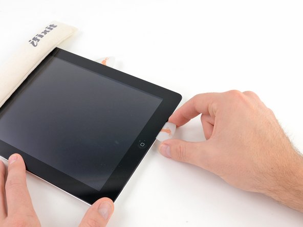
– Spot a tiny gap in the adhesive ring at the upper right corner of your iPad, about 2.0 inches (~5 cm) from the top. This little flaw is your entry point!
– Get ready to align your tool with the mute button. Gently insert the tip of a plastic opening tool into that gap between the front glass and the plastic bezel. Just the tip—enough to give that crack a little nudge!

Step 9


– With the plastic opening tool firmly nestled between the front glass and plastic bezel, gently slide a plastic opening pick into the gap right next to it. You’re doing great!
Step 10


– Gently take out the plastic opening tool from your iPad, then slide the opening pick a little deeper under the front glass—aim for about half an inch. You’re doing great!

Step 12


The adhesive is super strong, so you might need to channel your inner Hercules! Take your time and be gentle with it.
If you spot the tip of your trusty opening pick peeking out from beneath the front glass, give it a gentle tug. While diving this deep with the pick won’t cause any harm, it might leave a little adhesive love on the LCD. Keep it cool, and remember, if you need help, you can always schedule a repair.
– While the iOpener warms up the bottom edge, let’s start peeling off the adhesive from the right side of your iPad.
– Gently slide the opening pick down the edge of the iPad, freeing that sticky stuff as you go along.
Tools Used
Step 13


You might find it helpful to slide the warmed iOpener back onto the right edge of the iPad as you peel away the adhesive. How long it needs to hang out there really depends on how cool the iPad has gotten while you were busy working your magic.
– If your opening pick is having a tough time and gets stuck in the adhesive, just give it a little ‘roll’ along the side of the iPad to keep on breaking that sticky bond.
Tools Used
Step 14


– Before you pop that first opening pick into the bottom corner of your iPad, slide a second pick under the right edge of the front glass. This little buddy will help keep the adhesive from getting sticky again.
– Give your iOpener a little heat love, then place it at the top edge of the iPad to keep things cozy.
Tools Used
Step 15

Hey there! Just a heads-up: the Wi-Fi antenna is snugly attached to the bottom right edge of your iPad’s rear case with screws and a cable. Since it’s positioned in a tricky spot, please handle it with care. A little extra caution goes a long way in preventing any permanent damage to the Wi-Fi antenna. You’ve got this!
– Alright, folks, it’s time to channel your inner repair guru! Just a heads up, the next few steps require a gentle touch.
– You’ll need to carefully detach the adhesive that’s holding the antenna to the front panel. Remember, we want to keep those delicate connections intact, especially the ones linking the antenna to the bottom of your iPad. So, let’s take it slow and steady through the next steps!
Step 16


Hey there! Just a quick heads up: try not to slide that pick past the bottom right corner. You might accidentally give the Wi-Fi antenna a little love tap, and we wouldn’t want that!
– Gently glide the opening pick around the bottom right corner of your iPad, freeing up that sticky adhesive like a pro!
Step 17


As you glide the opening pick along the bottom right edge of the front panel, keep in mind that the Wi-Fi antenna is lurking nearby. Be careful, as it’s easy to accidentally snip it if the adhesive is released the wrong way. Stay sharp and take your time!
Just a little tip here: don’t yank that pick all the way out from under the front glass! Give it a gentle pull so that about 1/8″ (3 mm) of the tip stays snugly underneath. You’ve got this!
– Gently glide the edge of your trusty opening pick along the bottom of the iPad, and watch as it releases the adhesive holding down the Wi-Fi antenna. You’re doing great!
Step 18

– Once you’ve gracefully glided past the Wi-Fi antenna (about 3 inches or 75 mm from the right edge, right near that trusty home button), slide that opening pick back in all the way.
– Now, give that pick a little nudge to the right to break free the adhesive holding the Wi-Fi antenna snug against the front glass.
Step 19


Keep your iOpener toasty, but don’t overdo it! Heat it for just a minute at a time and give it a little break—at least two minutes—before you warm it up again. Your device will thank you for the extra care!
If the adhesive has gotten a bit too cozy and cooled down along the bottom edge, just give that iOpener a little reheat love to warm things up where you’re working.
– Keep easing off that adhesive along the bottom of your iPad! Gently pull the opening pick out far enough to glide around the home button, and once you’re past it, slide that pick back in about 1/2 inch (10 mm). You’ve got this!
Tools Used
Step 20


– Keep peeling away that adhesive along the bottom edge of your iPad like a pro!
– Nestle the opening pick snugly under the front glass near the home button—it’s like a cozy little spot for it!

Step 22


If your adhesive has gotten a bit too cool, just swap in the iOpener along the top edge and keep at it! And hey, if the iOpener is feeling a little chilly, give it another heat-up. You’re doing great!
– Gently slide the opening pick along the top edge of your iPad, giving it a little tug to navigate around the front-facing camera bracket.
– The adhesive in this area is pretty tough, so don’t hesitate to use some muscle. Just take your time and stay focused to avoid any slips that might lead to a mishap with your iPad.
– If the opening pick seems to be stuck in the adhesive, try ‘rolling’ the pick as demonstrated in step 9.
Tools Used
Step 23


If the adhesive is feeling warm and cozy, go ahead and take that iOpener off the iPad for a smoother experience. But if it’s still a bit clingy, just give the iOpener another heat-up and place it on the left edge while you tackle the task at hand. You’ve got this!
– Keep peeling away the sticky stuff along the top edge of your iPad, and gently maneuver the opening pick around that top left corner like a pro.
Tools Used
Step 24


The digitizer cable is hanging out about 2 inches (50 mm) from the bottom of your iPad. When you’re sliding that pick, just ease up when you hit around 2.25 inches (60 mm) from the bottom. You’ve got this!
– Gently slide that opening pick down the left edge of your iPad, letting the adhesive loosen up as you go. It’s pretty thin here thanks to the digitizer running along the whole left side. Just keep the pick at a shallow depth (no more than 1/2 inch or 10 mm) to avoid any mishaps with the digitizer. You’ve got this!
Step 25

Hey there! Just a heads up, the digitizer cable is hanging out just about an inch (25 mm) from the bottom of your iPad. Take your time and be super gentle so we don’t accidentally cut this little guy!
– With the trusty opening pick still nestled under the bottom edge of your iPad, gently work it to loosen the adhesive in the bottom left corner.
Step 26

– Grab one of those handy opening picks and gently lift up the bottom right corner of your iPad. Use your fingers to hold it steady and give yourself a little pat on the back for tackling this repair like a pro!
Step 27


Watch out for any sticky stuff that might still be hanging around! Grab an opening pick to gently slice through any adhesive still keeping that front panel in place.
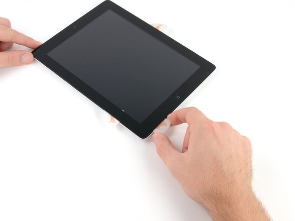
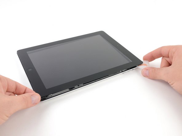
– Grab your iPad by the top and bottom right corners and gently twist the front glass away from the device. Easy peasy!
– When you’re putting everything back together, remember to whip out a microfiber cloth and some compressed air to give that LCD a little TLC—clean off any dust bunnies or fingerprints before you seal the deal with the glass.
Step 28

– Time to get your hands a little dirty! Start by unscrewing those four 2.0 mm Phillips screws that are holding the LCD snugly to the rear case. You’ve got this!
Step 29


The front panel ribbon cables are hiding just beneath the LCD. To get to them, you’ll need to gently flip the LCD over and set it aside for a moment. You’ve got this!
– Gently lift the LCD from the edge that’s closest to the volume buttons and flip it out of the rear case, just like you’re turning the page of your favorite book.
– Carefully place the LCD face down on the front panel, making sure it’s cozy and secure.
Step 30

– Gently lift off the rubber cover from the metal camera retainer and take it out of your iPad 2.
Step 31


Make sure that little thermal pad is snugly on the metal retaining clip, just like in the third picture, when you’re swapping out that rear-facing camera!
– First up, let’s tackle those two pesky screws—remove them with a smile!
– Next, gently lift the metal retainer clip straight up from its cozy spot in the rear panel. You’ve got this!
Step 32


– Grab a plastic opening tool and gently pop the rear camera connector up from its cozy spot on the control board. It’s like giving it a little nudge to say, ‘Hey, time to come out!’
– Now, let’s remove the rear-facing camera. Give it a little tug, and it should come right off!
Step 33

– Unscrew the screws holding the volume/power button assembly cable in place and let the fun begin!
Step 34

– Take off the metal bracket that’s holding the rotation lock/silent switch in place. You’ve got this!
Step 35


– Gently pull the power button cable out from its cozy spot in the rear case and give it a little bend to the side.
– Keep in mind, the ribbon cable holds the mechanical button that needs to snugly fit with the plastic button cover still hanging out in the case.
Step 36


– Let’s kick things off by carefully taking out the sleep/power button from the back case. You’ve got this!
– Remember to keep an eye on how everything fits together for when it’s time to put it back. The metal spring bar should gracefully drop down towards the back of the case.
Step 37


Keep that bracket in place! It’s still connected to the button ribbon cable, so let’s not give it a free ride just yet.
– Grab that volume control bracket and give it a little tilt using the center screw hole. Pull it gently towards the edge of the case, then lift it right out of its cozy spot! You’re doing great!
Step 38

– Carefully lift the power button part of the cable away from the back case, like you’re peeling a banana—nice and easy!
Step 39


– Carefully lift the cable that connects the power button to the volume rocker away from the rear case.
Step 40


– Gently bend the cable inward toward the rear case, but hold your horses and don’t pull it out just yet—it’s still happily connected to the upper component board.
Step 41


– Let’s kick things off by taking out that rotation lock/silent switch from the back of the case. You’ve got this!
– Remember how everything fits together for when it’s time to reassemble. The mechanical switch needs to click into that button cover just right, so make sure they snugly interlock.
Step 42


– Grab your trusty spudger and gently nudge that volume rocker inward into the cozy confines of the rear case.
– Now, go ahead and pop that volume rocker right out of the rear case. Easy peasy!
Step 43


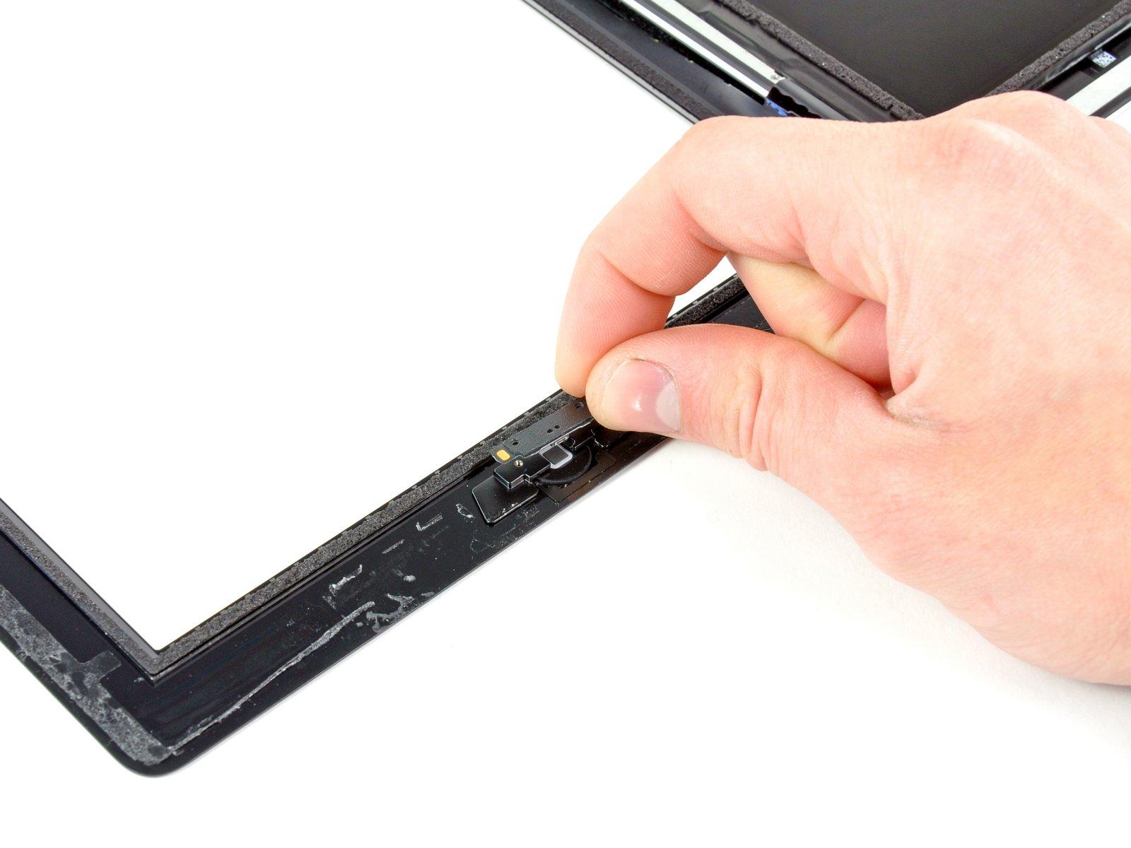
– Gently use the tip of an opening pick to lift the Smart Cover sleep/wake sensor off the back of the case. You’re doing great!
Step 44


– Gently peel back the volume rocker section of the button cable from the rear case. You’ve got this!
Step 45


Hey there! Just a quick reminder: don’t yank that cable out completely! It’s still attached with a connector that’s taped to the upper component board. Keep it gentle and you’ll be just fine!
– Carefully peel away the last vertical section of the rear case like you’re unwrapping a present.
Step 46

– Unscrew that lone 2 mm Phillips #000 screw from the bottom of the upper component board. You’ve got this!
Step 47


– Grab your trusty tweezers and gently lift that foam block out from its cozy spot nestled between the rear case and the upper component board. You’ve got this!


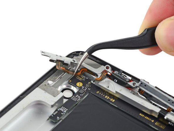
Step 50


Be sure to gently slide the cable out instead of lifting it straight up as you disconnect it. Let’s keep everything nice and safe!
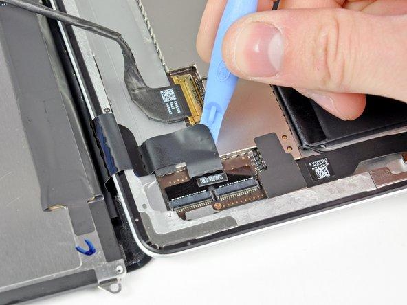
– Lift the retaining bar to free the upper component board cable connector. You’ve got this!
– Gently pull the connector straight out of its socket on the logic board. Easy peasy!
Step 51


– Gently peel the upper component board cable away from the sticky adhesive that’s keeping it snug against the rear case. You’ve got this!
Step 52


Gently tug on the cable of the upper component board as you lift it up just enough to clear the battery—make sure not to raise it too high to avoid any scratches on the rear case. Take your time and be cautious; you’ve got this!
– Gently slide the tip of your trusty spudger under the upper component board to give it a little lift-off action.
– Carefully pull the board up and out from its cozy spot nestled between the battery and the rear case bezel.
– Say goodbye to the upper component board as you remove it from the device.
– When you’re putting things back together, don’t forget to reconnect the GPS antenna cable at this stage. Grab those tweezers and take your time. Oh, and feel free to pop in the 2 mm Phillips #000 screw from the lower end of the upper component board—just thread it in lightly for now. We’ll tighten everything down once all the upper component board screws are in their happy place.
Step 53


– Gently remove the tape that’s holding down the button cable connector from the upper component board. You’ve got this!
Step 54


– Gently lift the button cable connector straight up off its perch on the upper component board. You’ve got this!
Step 55


If your replacement part already has the metal button brackets in place, you can breeze right past the next steps!
– Gently remove the power button from its cozy spot on the power button bracket.
– Remember how it was sitting and where the sticky stuff goes for when you put it all back together!
Step 56


– Slide the tip of an opening pick between the rotation lock/silent switch and its bracket to break that adhesive bond.
Step 57


– Gently slide the opening pick beneath the leftover part of the rotation lock/silent switch and lift it away from the button bracket.
Step 58


– Gently slide the point of your opening pick under the mechanical volume buttons and lift them away from the bracket with a little finesse.
– Carefully detach the button cable assembly from its cozy spot on the button bracket.