How to Replace iPad Apple Wi-Fi Speakers Tutorial
Duration: 45 minutes
Steps: 20 Steps
Hey there! Just a friendly reminder: be super careful while working on your device. It’s like handling a delicate flower! If things get tricky or you need a hand, don’t hesitate to schedule a repair. We’re here to help!
Swap out that speaker assembly and bring the sound back to your iPad. Let’s get those tunes playing again!
Step 1


Rock those safety glasses to keep your peepers safe, and watch out for that LCD screen – we want it in one piece!
– If your display glass is a bit worse for wear, let’s keep things safe and sound! Grab some tape to hold that glass together and protect yourself while you work.
– Start by laying down overlapping strips of clear packing tape across your iPad’s display until it’s completely covered. This will help contain any wayward shards.
– Do your best to follow the rest of the guide as outlined. Just a heads-up: once the glass starts to crack, it might keep on doing its thing as you proceed. You may need to use a metal prying tool to carefully scoop out the glass.
Step 2


– There are 14 metal clips that keep the display assembly snug as a bug, as you can see on the left. When you start prying in the upcoming steps, be sure to navigate around these clips like a pro, avoiding slicing through them with your trusty opening tool. You’ve got this!
Step 3


– Gently slide a metal spudger between the upper edge of the display assembly and the rear panel assembly.
– Give that spudger a little twist away from you to pop those tabs loose along the top edge of the display.
– Now, slip in a second metal spudger between the top edge of the display assembly and the rear panel assembly to keep those tabs from snapping back in place.
Tools Used

Step 4


Pry with care and a light touch—if you hit a snag, take a breather and try another spot.
– Grab your trusty spudger and gently glide it along the right edge of the iPad.
– The front panel is fastened to the aluminum back with metal clips at the top, bottom, and left sides. The right side is held by some sneaky plastic tabs that slide into grooves in the backplate.
– Once you’ve freed those clips, lift the left side of the front panel and slide it to the left to pop those tabs out from the aluminum backplate.

Step 6

– Alright, let’s get you set up for success! In the next few steps, we’ll be gently detaching the three cables that connect the display assembly to the logic board. These cables are responsible for some important components, so let’s handle them with care!
Step 7


Just a friendly reminder: lift the retaining flap, not the socket itself!
– Grab your trusty plastic opening tool and gently nudge those little retaining flaps up so the digitizer ribbon cables can wiggle free from their cozy sockets on the logic board.
– Now, with a steady hand, pull those digitizer ribbon cables straight out. You’ve got this!
Step 8

– Grab a trusty plastic opening tool and gently nudge the ambient light sensor connector upwards to pop it out of its socket. You’ve got this!
Step 9


Gently slide the connector out parallel to the logic board’s surface.
– Gently lift the metal retainer using its handy black plastic pull tab to free the display data cable from the main board.
– Carefully pull the cable connector away from its cozy socket.

Step 11

– Take out those two 4.56 mm T5 Torx screws that are holding the dock connector cable down to the main board. You’ve got this!
Step 12

– Unscrew the lone 2.84 mm T5 Torx screw that’s holding the dock connector cable to the rear case assembly. You’ve got this!
Step 13

– Take a moment to locate the two 2.84 mm T5 Torx screws that are holding the dock connector cable snugly against the rear panel assembly. Once you’ve found them, give them a gentle twist and remove them like a pro!
Step 14

– Gently lift off the plastic cover shielding the WiFi/Bluetooth board and dock connector cable using a trusty plastic opening tool. You’ve got this!
Step 15

– Gently lift the Wi-Fi and Bluetooth antennas off their cozy homes on the Wi-Fi/Bluetooth board. They’ll be just fine, promise!
– Carefully detach the dock connector cable from the rear panel assembly. It’s like giving it a little goodbye wave!
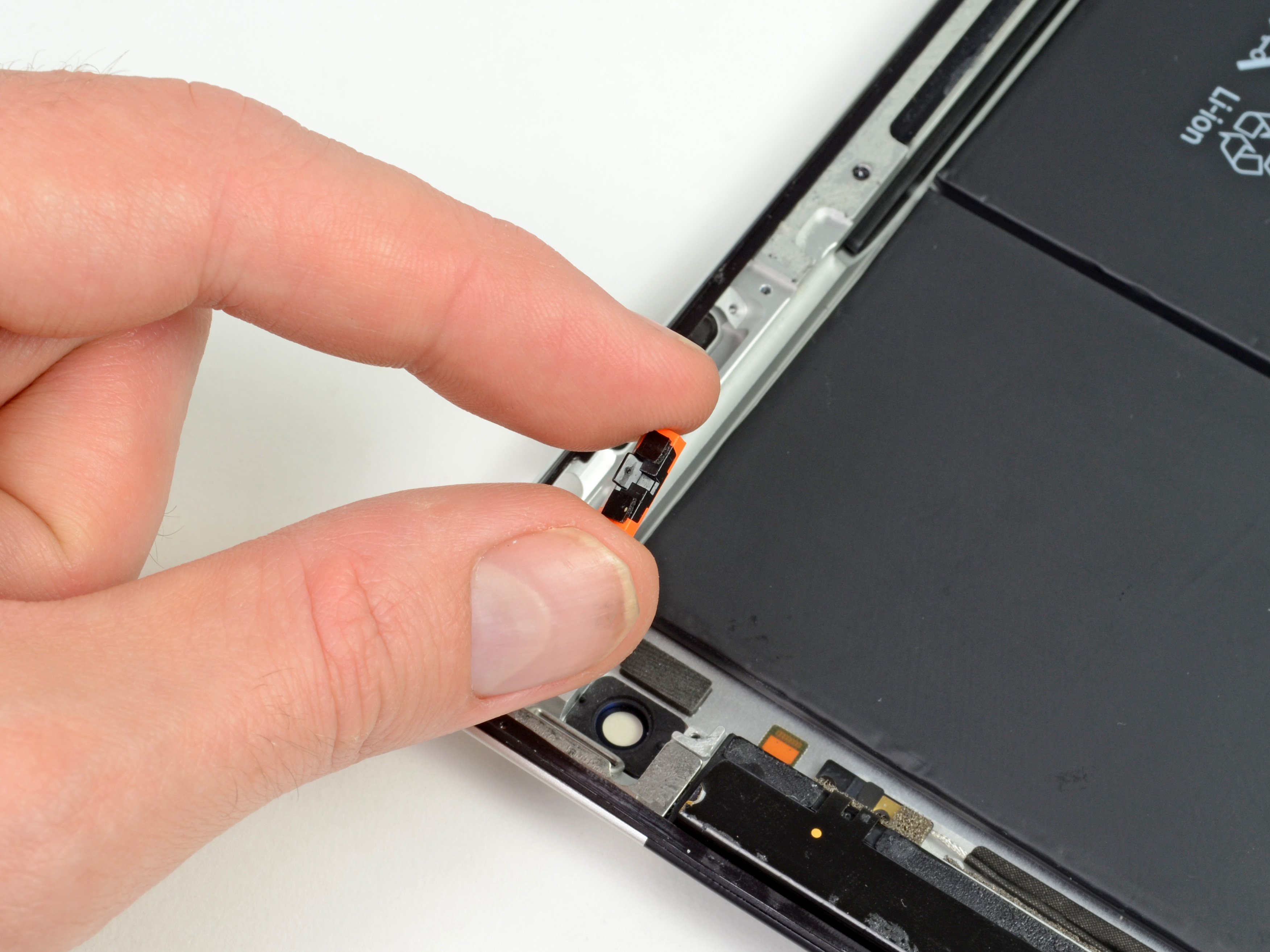
Step 16

Gently lift from underneath the wires to get things moving.
– Gently pry the speaker connector away from the logic board using the edge of a trusty plastic opening tool. You’ve got this!
Step 17

If needed, peel away the tape that’s snugly hugging the Wi-Fi cables.
– Unscrew those two 2.84 mm T5 Torx screws that are keeping the speaker assembly snugly attached to the rear panel assembly. You’ve got this!

Step 19

– G
– e
– n
– t
– l
– y
–
– g
– u
– i
– d
– e
–
– t
– h
– e
–
– s
– p
– e
– a
– k
– e
– r
–
– c
– a
– b
– l
– e
–
– c
– o
– n
– n
– e
– c
– t
– o
– r
–
– t
– h
– r
– o
– u
– g
– h
–
– t
– h
– e
–
– l
– e
– f
– t
–
– s
– i
– d
– e
–
– o
– f
–
– t
– h
– e
–
– r
– e
– a
– r
–
– p
– a
– n
– e
– l
–
– a
– s
– s
– e
– m
– b
– l
– y
– .
–
– Y
– o
– u
– ‘
– v
– e
–
– g
– o
– t
–
– t
– h
– i
– s
– !
Step 20

– Gently lift the speaker assembly and nudge it forward until the ports clear the bottom of the rear panel assembly. You’re almost there!
– Carefully take the speaker assembly out of the rear panel assembly. You’ve got this!