
How to Replace iPad Pro 9.7 Battery: Step-by-Step Guide
Duration: 45 minutes
Steps: 126 Steps
totally out of juice
Ready to give your iPad Pro 9.7” a new lease on life? This guide will show you how to swap out that old battery with ease. You’ll need to wiggle the logic board out first to make room for the battery swap. Rocking a cellular model? Kick things off with the first step. If not, just skip it and dive right in. Keep your iPad powered on and let the battery drain completely before you start—this way, you’ll avoid any unexpected zaps! Grab your high-concentration isopropyl alcohol to breeze through any sticky situations. Oh, and if your battery looks puffy, handle it with care!


Step 2


Pop on some safety glasses to shield those peepers, and let’s be careful not to bust that LCD screen while we’re at it!
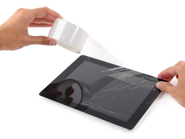
– Got a cracked screen? No sweat—let’s keep those pesky shards in check and avoid a DIY disaster by slapping some tape over the glass.
– Start by laying overlapping strips of clear packing tape across the face of your iPad’s display until it’s fully covered. This will keep the glass secure and prevent any loose bits from escaping.
– Try to stick to the guide as closely as possible. But hey, cracked glass does what it wants, and it might just decide to crack a bit more as you go. If it gets too wild, you might have to bring in a metal prying tool to help clear out the glass.
Tools Used

Step 3

The next steps will have you cozying up with an iOpener to loosen the adhesive that’s keeping the front panel assembly snug. Remember to heat your iOpener in the microwave for no more than 30 seconds—just a quick zap!
– Grab the iOpener by its tabs and give your iPad’s top edge a warm embrace with it.
– Let the iOpener hang out there for two minutes to loosen up that stubborn adhesive holding the front panel in place.
Tools Used

Step 4


Though your iPad might look slick and seamless on the outside, it’s like a secret party of delicate parts underneath that glass. Make sure you heat and pry only where we tell you in the steps to keep the party going without any party-poopers!
– As you dive into the directions, remember to tread lightly around these zones to keep your device happy and healthy!
Step 5


The upcoming two steps showcase the Anti-Clamp, our special tool designed to simplify the opening process. If the Anti-Clamp isn’t part of your toolkit, just hop down two steps for an alternative technique.
– Prop up your iPad so the Anti-Clamp’s arms are chilling above and below the screen—just hanging out.
– Give the blue handle a friendly tug towards the hinge to pop out of opening mode.
– Snag a spot near the top edge of the iPad for the suction cups—one on the front and one on the back, like a cool hat.
– Press down on those cups to get a good, snug suction. Stick ’em well!
Step 6


– Slide the blue handle away from the hinge to kick off the opening party.
– Crank that handle clockwise until the cups start doing their stretchy dance.
– Hang tight for a minute to let the sticky stuff get a hint and loosen up, making a gap.
– When the Anti-Clamp works its magic and pops open a big enough gap, sneak an opening pick under the screen.
– Feel free to skip the next two steps and keep cruising forward.
Step 7


– Pop a suction cup just above the iPad’s selfie cam and give it a smooth press to stick it like glue.
Step 8


– Give that suction cup a hearty tug to pry open a nifty little gap between the front panel and the rear case.
– Got that gap going? Awesome! Slip an opening pick into that space to keep that sneaky adhesive from sticking back together.
Step 9


– Glide the pick toward the headphone jack, cruising along the edge of the display. Keep it cool and steady, you’re doing great!


Step 11


– Scoot the second pick across the top edge of your iPad, heading towards the Sleep/Wake Button. Keep it groovy!
Step 12


– Pop in another pick right by the selfie snapper!
Step 13


– Swoosh that right opening pick down and swing it around the top right corner of the iPad like you’re scoring the winning goal!
Step 14


– Swing the left opening pick around the top left corner of the tablet like you’re rounding the bases after a home run!

Step 16


– Glide the right opening pick about halfway down the display like a mini skateboard. Keep it groovy!
Step 17

– Warm up that iOpener again and give the left side of your iPad some heat love!
Tools Used
Step 18


– Glide the left-hand opening pick down about halfway through the side of the display. Keep it cool and steady, you got this!


Step 20


– Glide the opening pick down the left edge of the screen all the way to the corner, like you’re skating on thin ice. Keep it smooth and steady, champ!
Step 21

– Heat up the party at the bottom edge of your iPad using the iOpener. Let’s get this repair started with some warmth!
Tools Used
Step 22


– Swing the opening pick around the bottom corner of the iPad like you’re rounding the bases after a home run!
Step 23


Keep the heat coming! If it cools down, just reheat the iOpener and slap it back on as needed.
– Do the same for the left-hand pick.
Tools Used
Step 24


– Whisk away that right-hand opening pick at the bottom of your iPad like you’re waving a magic wand!
Step 25


– Whizz your left-hand opening pick along the bottom edge of the screen, then pop it out from the bottom right corner of the iPad. Keep it groovy!
Step 26


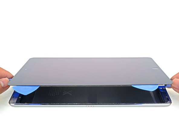
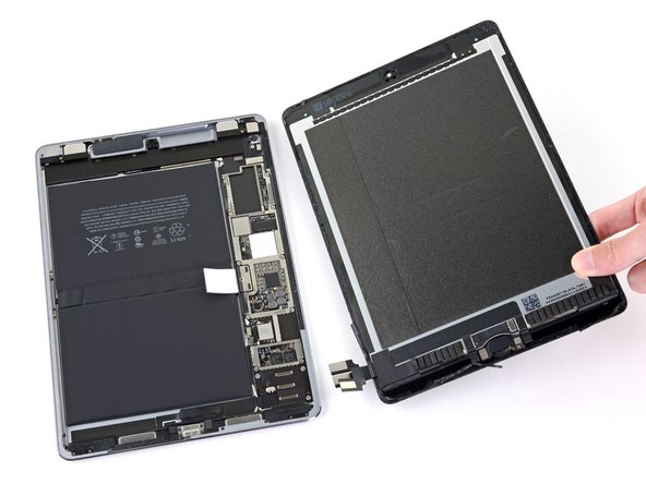
Hold up! Don’t try to yank off the display just yet—it’s still connected to the back. Let’s keep everything in one piece, shall we?


Step 28

– Grab your trusty Phillips screwdriver and pop out those eleven 1.3 mm screws holding down the EMI shield. If you need help, you can always schedule a repair.
Step 29

– Get cozy with the logic board by gently applying a warm iOpener to the EMI shield for about a minute.
Tools Used
Step 30


– Start by coaxing the logic board EMI shield off, beginning at the top edge closest to the iPad’s noggin.
– Gently persuade the EMI shield to detach from the logic board with a slow peeling motion.
– Wave goodbye to the logic board EMI shield as you remove it.
Step 31

– Grab your Phillips driver and unscrew the 1.7 mm-long screw that’s keeping the battery connector in place.
Step 32


– If that EMI shield is giving you the spiky attitude after removal, go ahead and smooth those edges before you pop it back in place.
– Grab a pair of pliers and give those unruly spikes a gentle squeeze to flatten them out.
– Do a quick repeat performance on all those spiky troublemakers around the edges of the EMI shield.
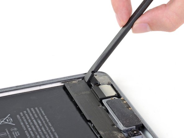
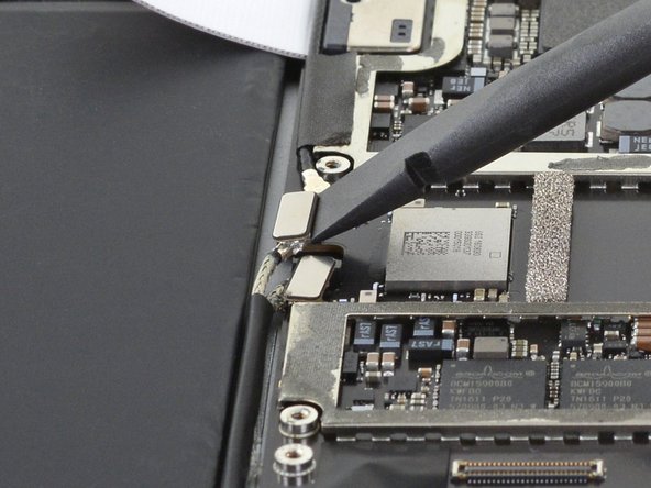
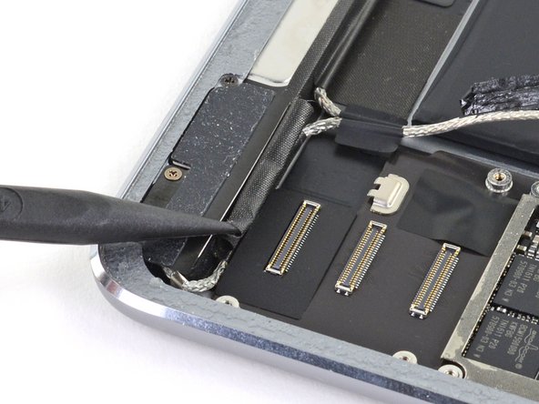
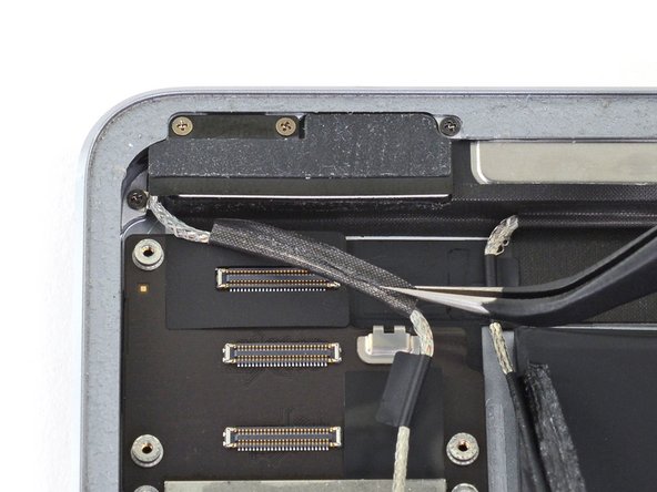
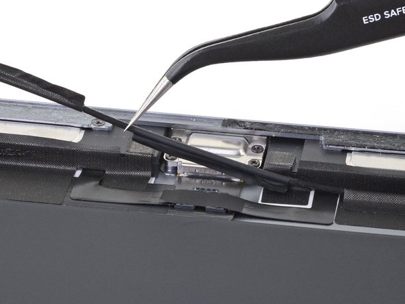
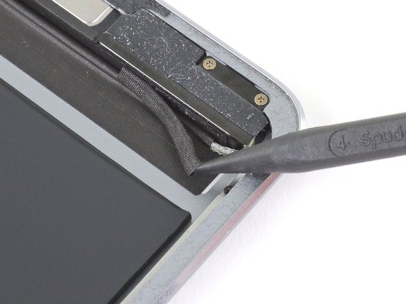
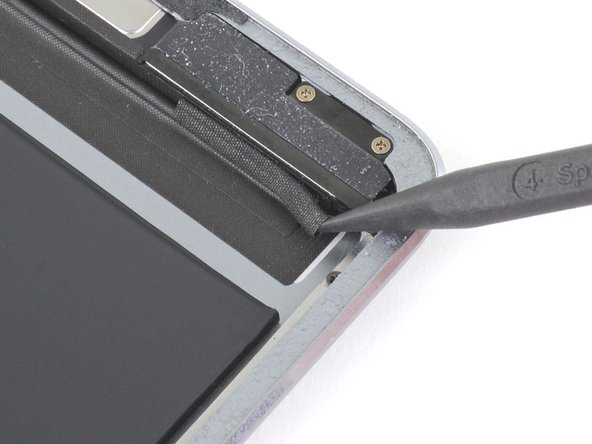
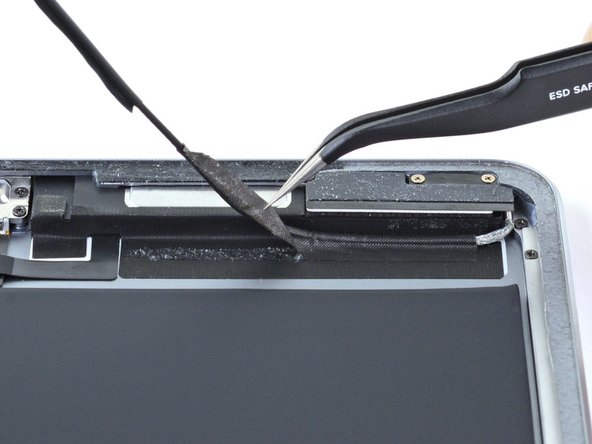
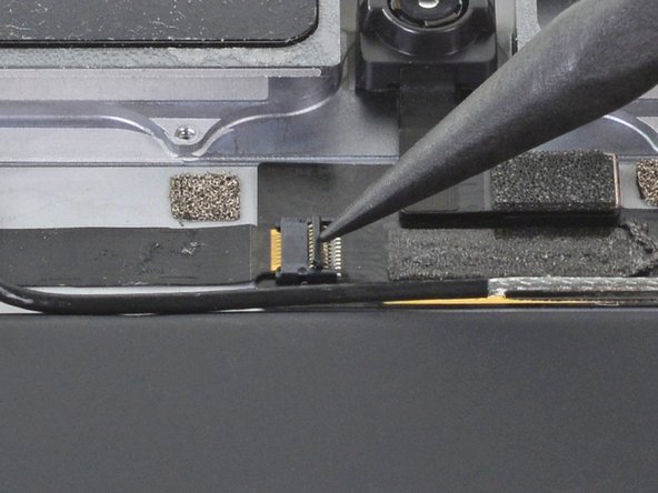
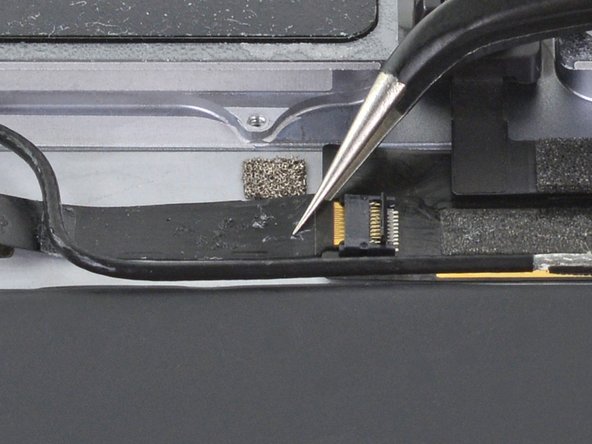
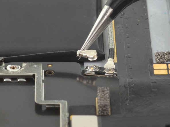
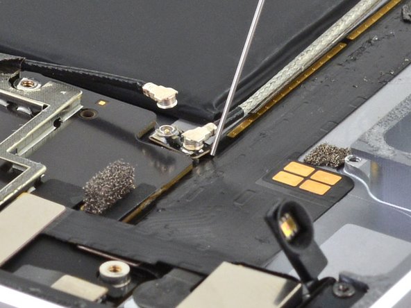
Step 33

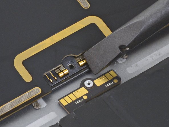
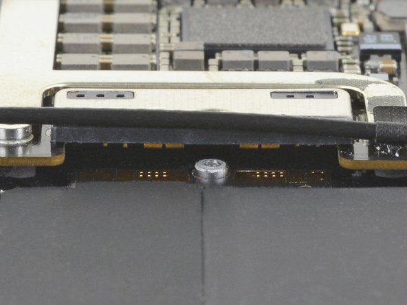
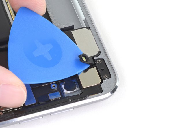
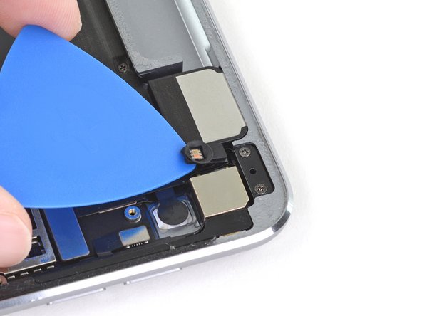
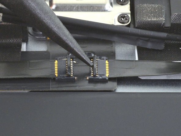
Check out these cool snapshots showing the hideout of the battery connector under the logic board. Keep these pics handy as a cheat sheet while you ninja your way through disconnecting the battery.
Peep this: The battery connector sports some nifty cantilever springs on the logic board that bump up against the battery’s contact pads. Both the logic board and battery are stuck down tight, so you’ll wanna slide something slim and nimble in there to break them apart.
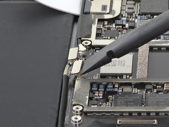
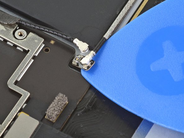
Step 34

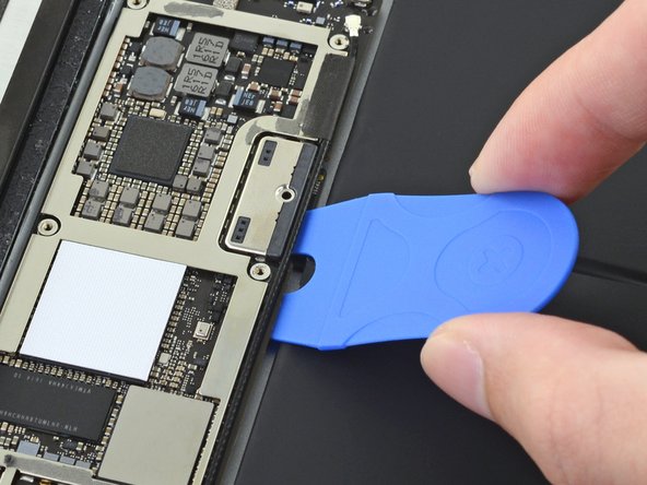
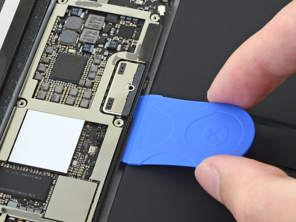
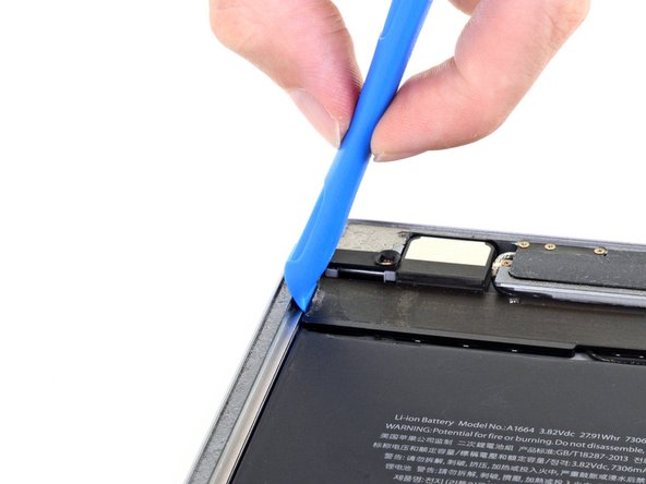
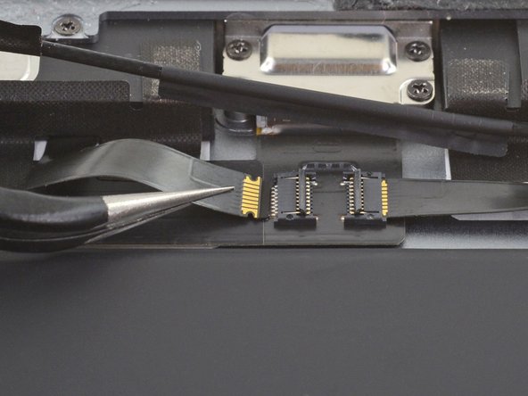
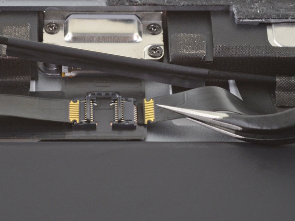
Watch out when you’re playing superhero with the battery blocker! Those battery contacts are delicate little things—bend or break them, and it’s game over for them, no respawns!
Make sure the iFixit logo on the battery blocker is sporting its best side up!
– Wiggle the battery blocker beneath the left side of the logic board’s battery connector at a sassy 35 degree angle.
– Keep that blocker snug under there while you continue your fix-it magic.
Tools Used

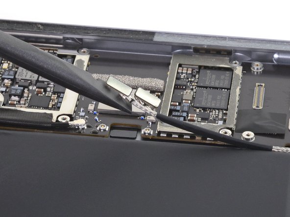
Step 35


If that pesky battery blocker is being a bit stubborn and won’t glide under the logic board smoothly, try these steps to give the logic board a little wiggle room from the frame:
Tools Used
Step 36

– Grab your Phillips screwdriver and twist out those three 1.3 mm Phillips screws that are holding the display cable bracket in place.


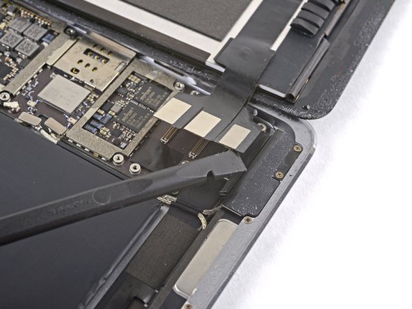
Step 38
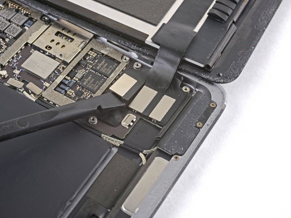

– Grab the flat end of your spudger and gently pop the display assembly connector off its socket on the motherboard. It’s like unplugging a tiny, delicate cable – easy does it!
Tools Used


Step 41

– Wiggle an opening pick under the right ambient light sensor to break up that pesky adhesive.
– Look for two little pegs on the shelf that help the ambient light sensor chill in the right spot—one peg hanging out at the bottom edge and another near the top.
Step 42

– Grab your Phillips screwdriver and let’s get those four 1.9 mm-long screws out that are keeping the upper speaker cozy with the frame.
Step 43


The upper speaker is glued down with some seriously stubborn adhesive. It’s not going anywhere without a fight!
– Drop a party of isopropyl alcohol (90% or higher—only the good stuff!) right under the upper speaker. Just a few drops, no pool parties!
– Hang tight for a minute! Let the isopropyl alcohol work its magic and soften the sticky stuff holding down the upper speaker.
Step 44

– Grab your opening tool and give the left edge of the upper speaker a gentle yet firm pry. Time to unleash the music maker!

Step 46


– Grab and detach the upper speaker from its mount.
– When putting it back together, ensure the right ambient light sensor sits snugly on its perch.
– If any alcohol residue lingers inside, dab it off gently or let it evaporate before popping the upper speaker back in place.


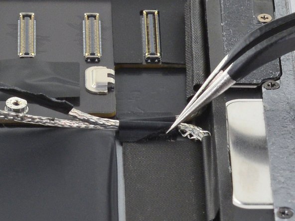
Step 50

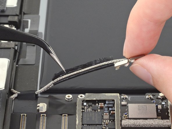
– Grab your tweezers and gently pluck out the sticky adhesive holding those antenna cables to the frame like you’re defusing a tickle bomb.
– When you’re putting it all back together, slap on some fresh pre-cut adhesive to those antenna cables to keep them snug as a bug on the frame.
Tools Used


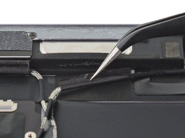
Step 52
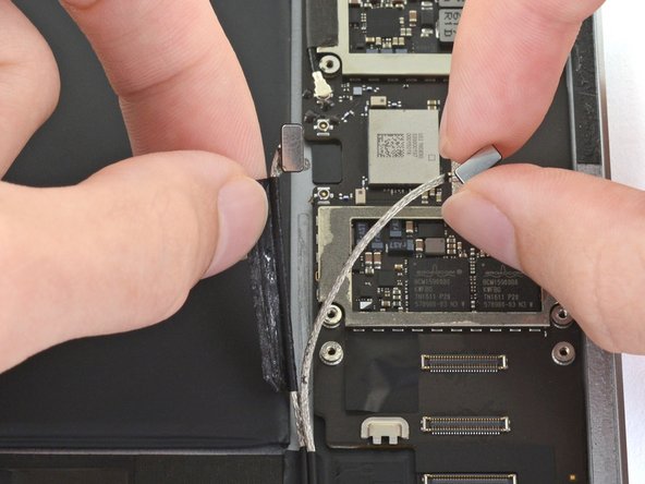

– Gently unleash the right antenna cable from its sticky slumber.


Step 55

– Yoohoo! Time to whisk away that foam spacer from the second right antenna sticker. Let’s keep it groovy and move on!
Step 56

– Grab your tweezers and gently peel off the big right antenna sticker that’s hanging out between the logic board and the antenna. It’s like separating two best friends—it’s necessary but handle with care!
Tools Used


Step 61

– Peel off the funky foam spacer from the fourth left antenna cable sticker like a boss!

Step 63

– Grab your tweezers and gently lift off the sticker hiding the left ambient light sensor’s ZIF connector. It’s like uncovering a little secret!
Tools Used
Step 64

– Grab the pointy end of your spudger and gently flip up the locking flap on the left ambient light sensor’s ZIF connector. It’s like lifting a tiny treasure chest lid!
Tools Used
Step 65

– Grab your tweezers and gently pinch the left ambient light sensor ribbon cable right near its contacts—like you’re picking a tiny flower!
– Gently tug that ribbon cable right out of its ZIF connector. It’s like unplugging a tiny electronic noodle—easy peasy!
Tools Used
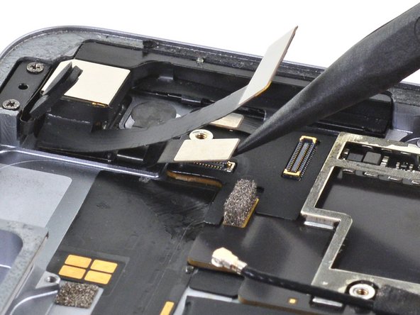
Step 66

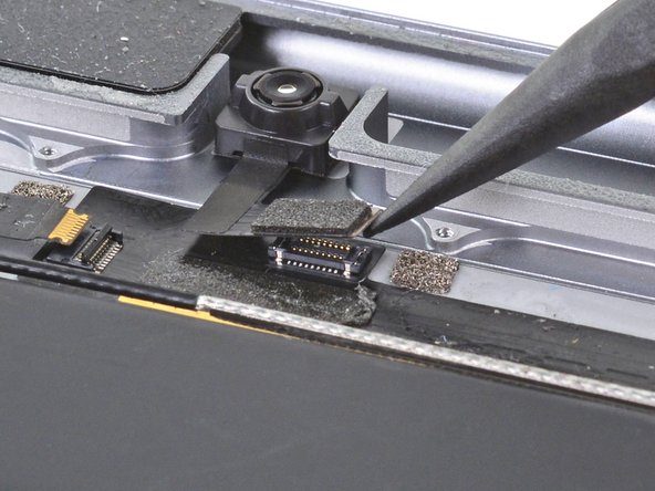
– Grab the pointy end of a spudger and gently pop off the front camera’s press connector from its cozy socket.
– When snapping it back into place, line the connector up just right and give it a gentle push with your fingertip—start on one side and then the other—until you hear a satisfying click.
Tools Used

Step 68

– Splash a couple of drops of the mighty 90% (or higher) isopropyl alcohol around the edges of the top interconnect board. It’s like giving it a little cocktail!
– Chill out for thirty seconds while the alcohol does its magic, softening the adhesive holding down the top interconnect board.
Step 69

– Grab your opening pick and show that adhesive who’s boss! Slice through the sticky stuff under the top interconnect board and pop it off the frame like a pro.
Step 70


– Grab your trusty spudger and gently use its pointed end to unplug the rear camera’s press connector from its cozy socket.
Tools Used
Step 71

– Grab your trusty spudger and use its pointed end to gently disconnect the power button assembly’s press connector from its cozy little socket.
Tools Used
Step 72

– Grab the pointy end of your spudger and gently pop the volume buttons’ press connector out of its cozy socket.
Tools Used
Step 73

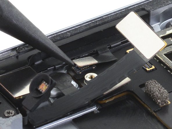
– Grab your tweezers and gently lift the sticker hiding the ZIF connectors near the Lightning port. It’s like finding a secret treasure!
Tools Used
Step 74


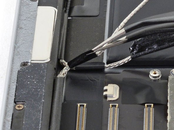
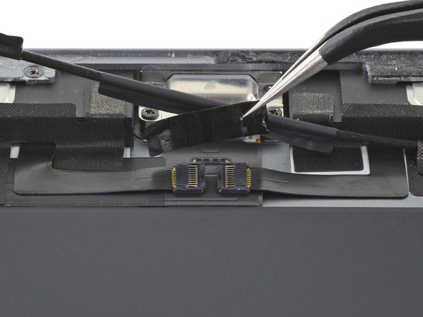
– Grab your opening pick and let’s make some magic! Slide it under the right ribbon cable near the lower speaker (make sure the Lightning port is smiling up at you). Gently wiggle that pick to say goodbye to the adhesive and free the cable from its frame prison.
Step 75

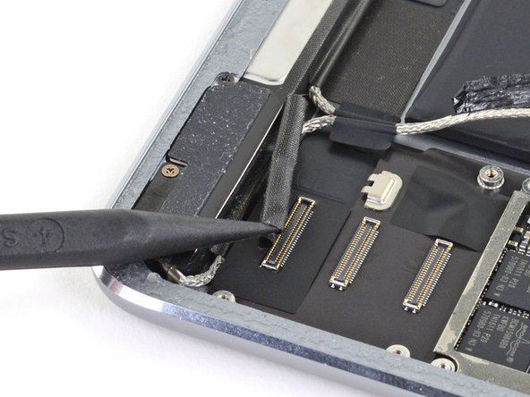
– Grab your opening pick and show that pesky adhesive who’s boss! Slice through the glue under the left ribbon cable next to the lower speaker to free it from the frame’s clutches.
Step 76
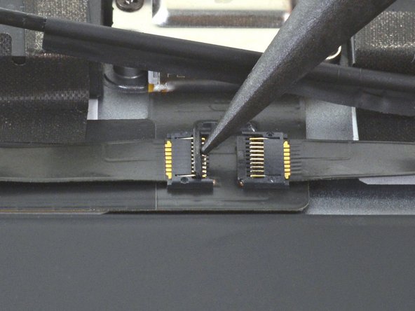

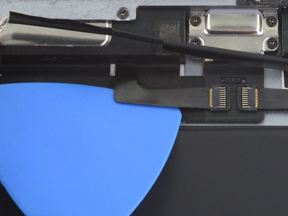
– Grab the pointy end of your spudger and give that little hinged locking flap on the left ribbon cable ZIF connector a gentle flip upwards. It’s showtime for that connector!
Tools Used
Step 77

– Grab the pointy end of your spudger and give that hinged locking flap on the right ribbon cable ZIF connector a cheeky flip-up. Let’s make this happen!
Tools Used
Step 78

– Grab your tweezers and gently pinch the left ribbon cable right near its contacts. Give it a smooth pull to slide it out of the ZIF connector. You got this!
Tools Used
Step 79

– Grab your tweezers and gently latch onto the right ribbon cable as close as you can to its contact buddies. Give it a smooth pull to slide it out of the ZIF connector. Nice and easy does it!
Tools Used
Step 80

– Unscrew the four Phillips screws holding the Lightning port in place:
Step 81
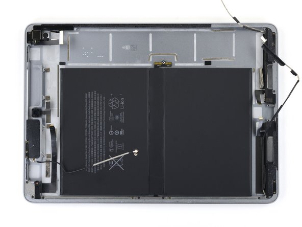

Check it out! Here’s your gadget stripped down with the logic board off. Exciting, right?
– The logic board is snugly stuck down with some sticky