How to Replace iPhone 5 Back Cover Guide
Duration: 120 min.
Steps: 47 Steps
In this guide, we show you how to replace your iPhone 5’s defective back cover. This repair can help if the back cover is warped or scratched, or if your rear camera no longer takes sharp pictures because the lens is scratched.
Step 1

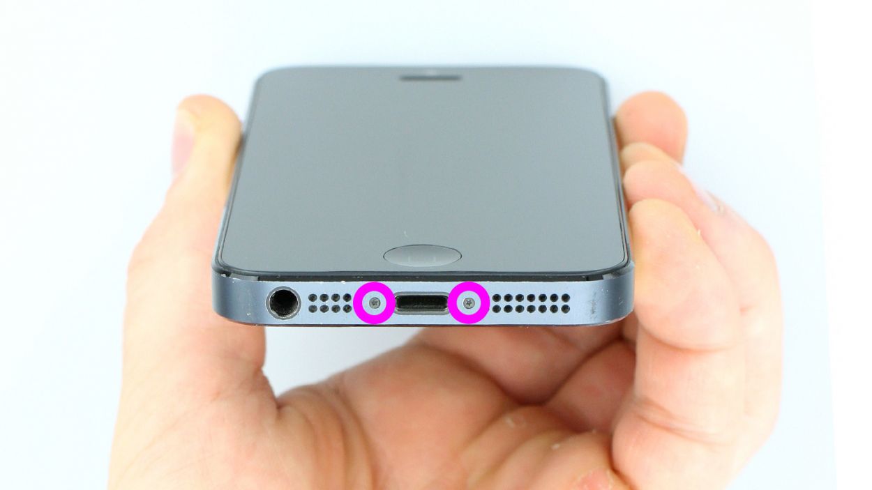
– Grab your trusty pentalobe screwdriver to get that iPhone 5 open!
– Now, let’s tackle those two pentalobe screws at the bottom of the enclosure. They’re hanging out right next to the Lightning connector, one on each side. Make sure to stash those screws in the same compartment of your organizer tray. You’ve got 2 x 3.6 mm pentalobe screws to keep track of!
Step 2

– Place your iPhone 5 on a soft, clean surface to keep that back looking sharp.
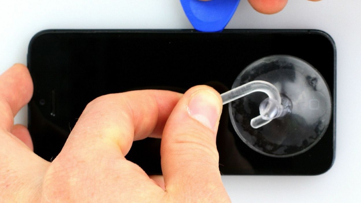
– To lift the front panel, grab a suction cup and a hard plastic pick. If your screen is looking a bit worse for wear, cover it with packing tape to keep things tidy.
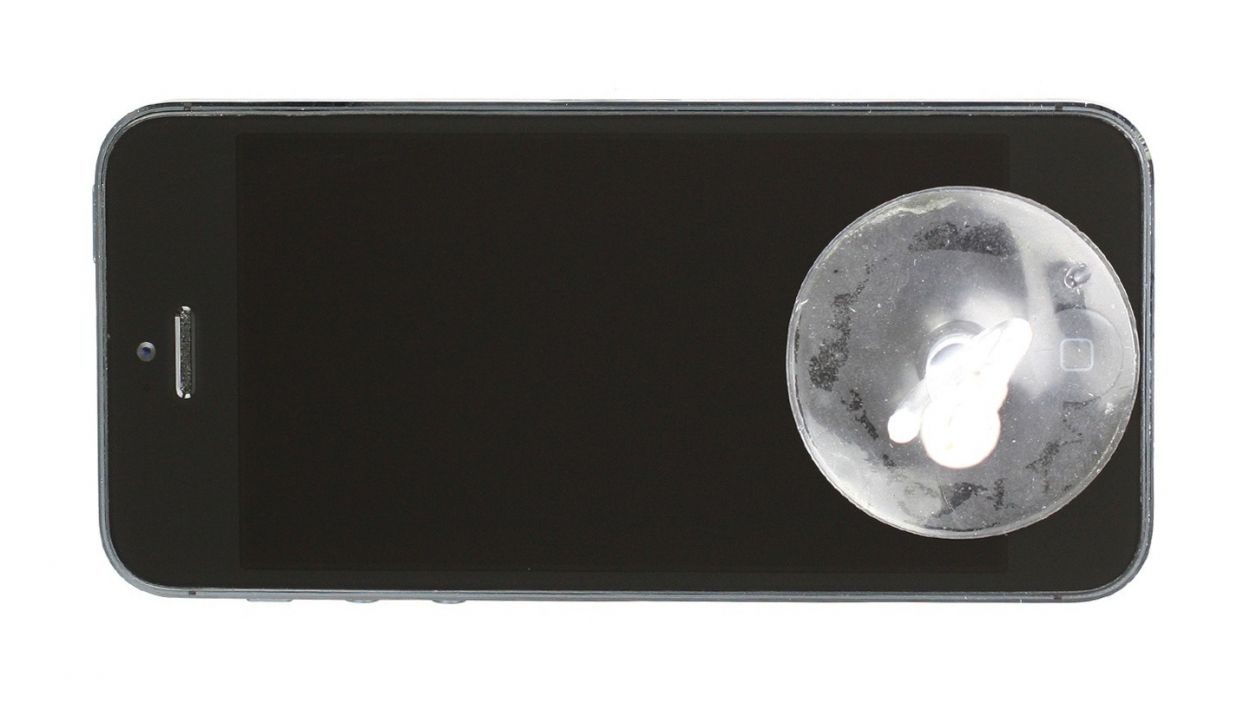
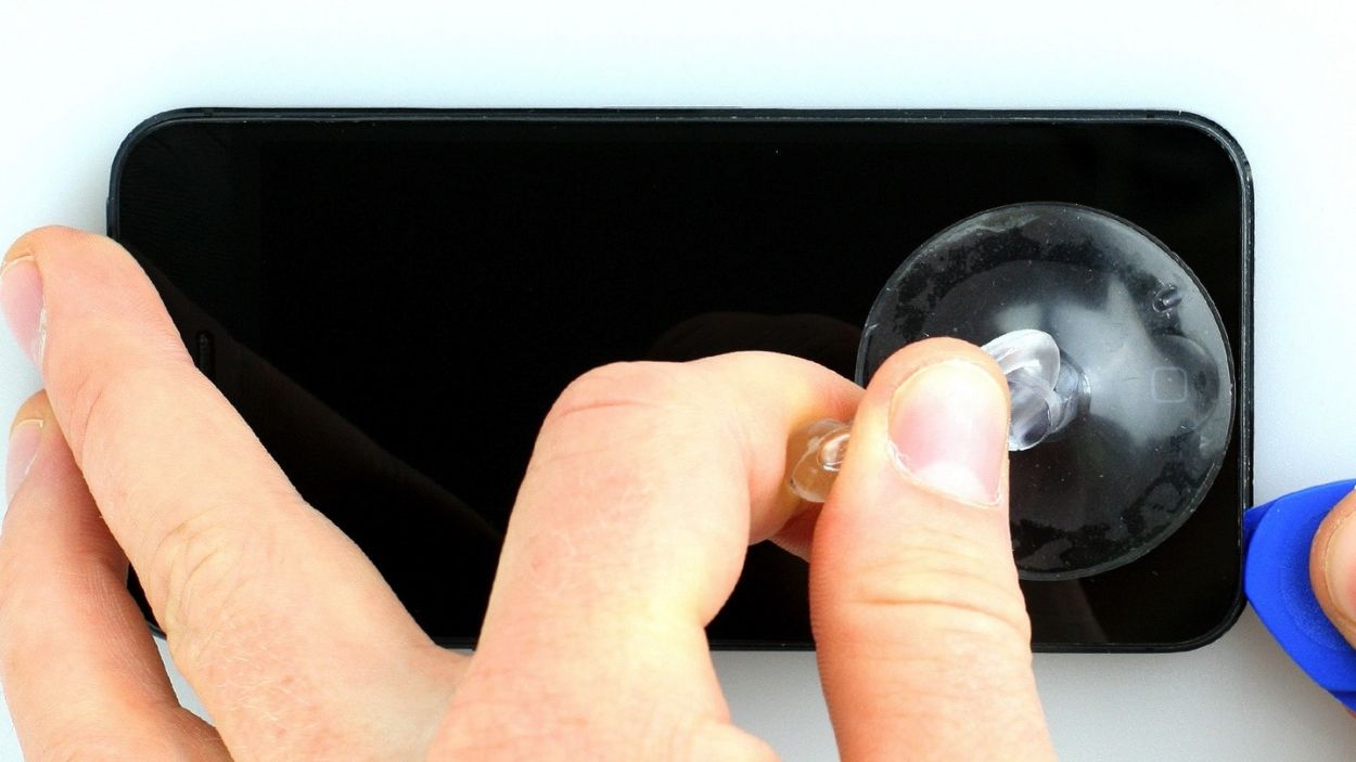
– Position the suction cup over the Home button (if you can) or right next to it (check out figure 1). While you gently pull up on the screen with the suction cup, slide the hard plastic pick between the aluminum frame and the display frame, pressing down on the aluminum frame. Use that pick to help lift the screen (see figures 2 and 3). It might take a few tries, but you’ve got this!
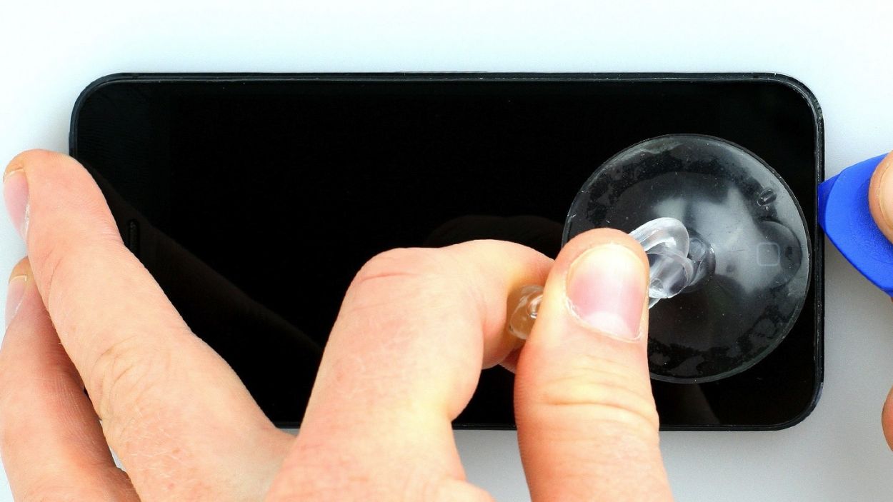
– Once you can lift the screen just a bit (see figure 4), carefully work your way around the edges until it’s loosened on both sides (see figure 5).
– When the display is fully free, you can flip it up at the Home button. Just a heads up, the display cables are still connected to the logic board (check out the next step).
Step 3
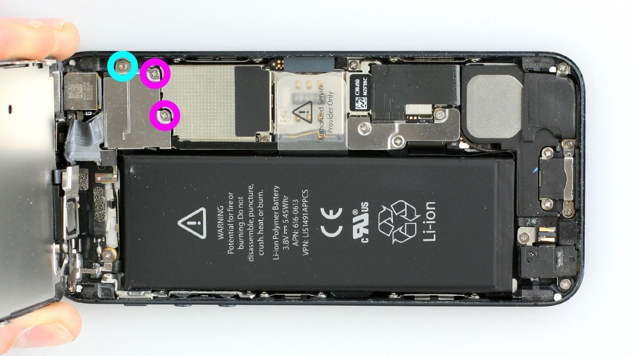

– First remove the three Phillips screws from the silver cover (see figure 1). Put the screws in the same compartment of your organizer tray.2 x 1.2 mm Phillips screws1 x 1.7 mm Phillips screw (not magnetic)
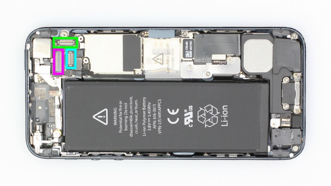
– Now you can disconnect the following three connectors (see figure 2). Be very careful.
– Place the pointed tip of the spudger very slightly below the contact and lift it up. Make sure you don’t break off the resistors that are soldered onto the logic board. In later batches of phones, the resistors are protected by a black plastic film.LCDTouchscreenFront camera/sensor/earpiece
Step 4
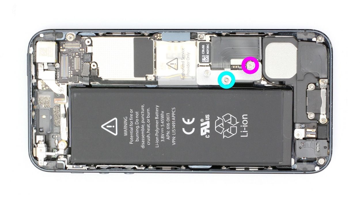
– Get ready to tackle the battery connector! Use your trusty Phillips screwdriver to remove those screws on the battery connector cover. Then, with a touch of finesse, lift the cover using the spudger. Remember to keep all the parts cozy in the same compartment of your organizer tray.
– Now, it’s time to delicately lift off the battery connector. Gently slide the pointed tip of the ESD spudger just below the connector. No spudger? No problem! You can give it a go with your fingernail.
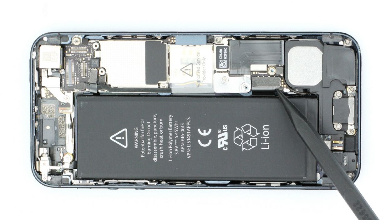
Step 5

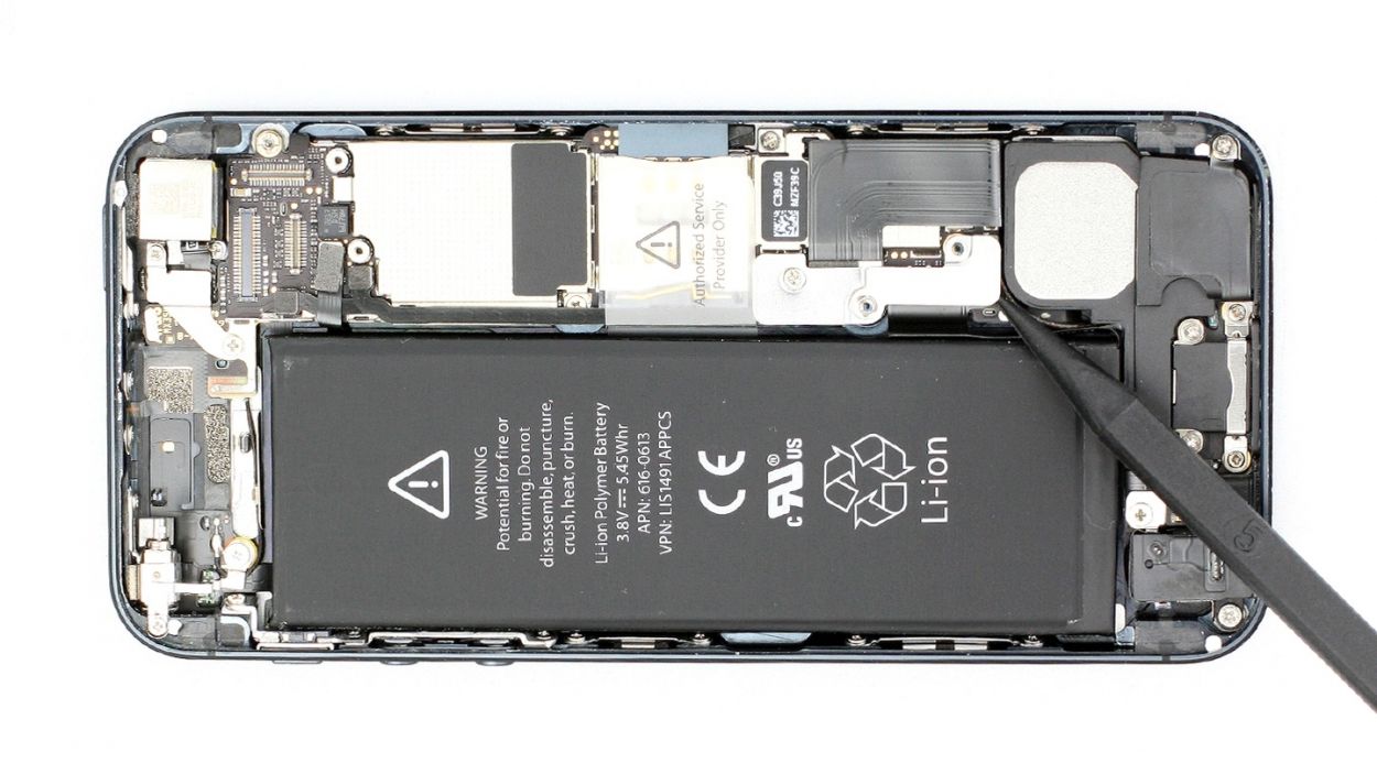
The logic board is super delicate, so handle it with care! You can also pop the battery out from the other side if you need to.
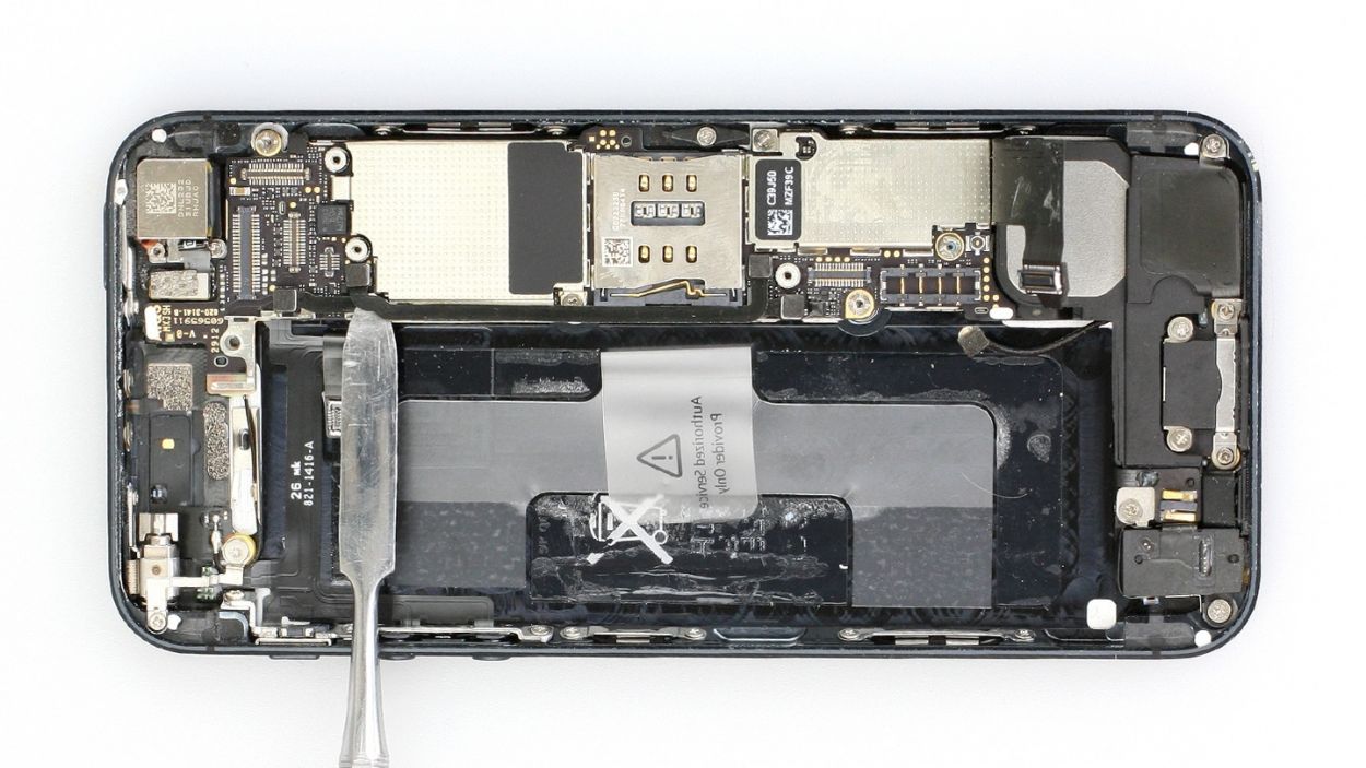
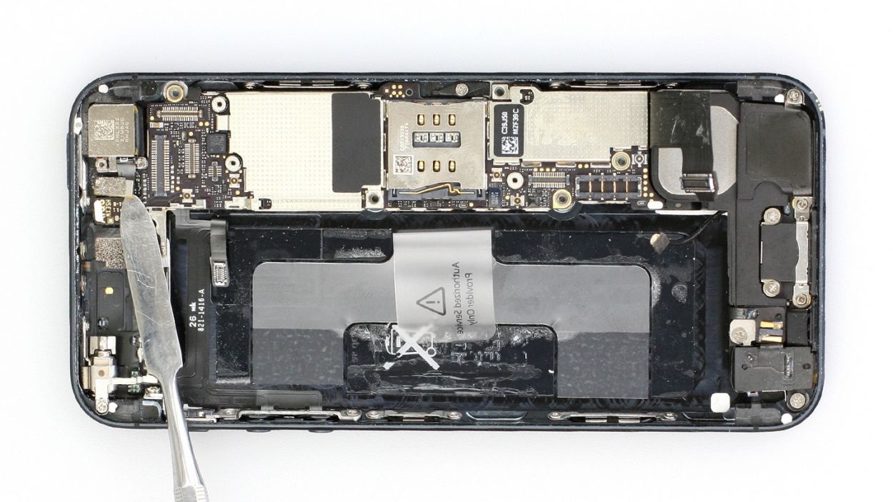
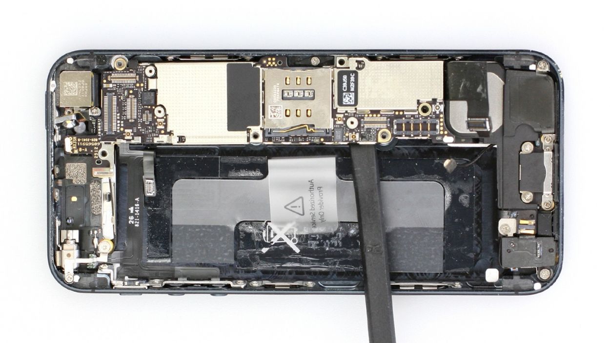
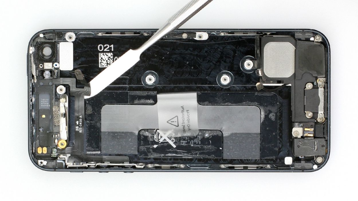
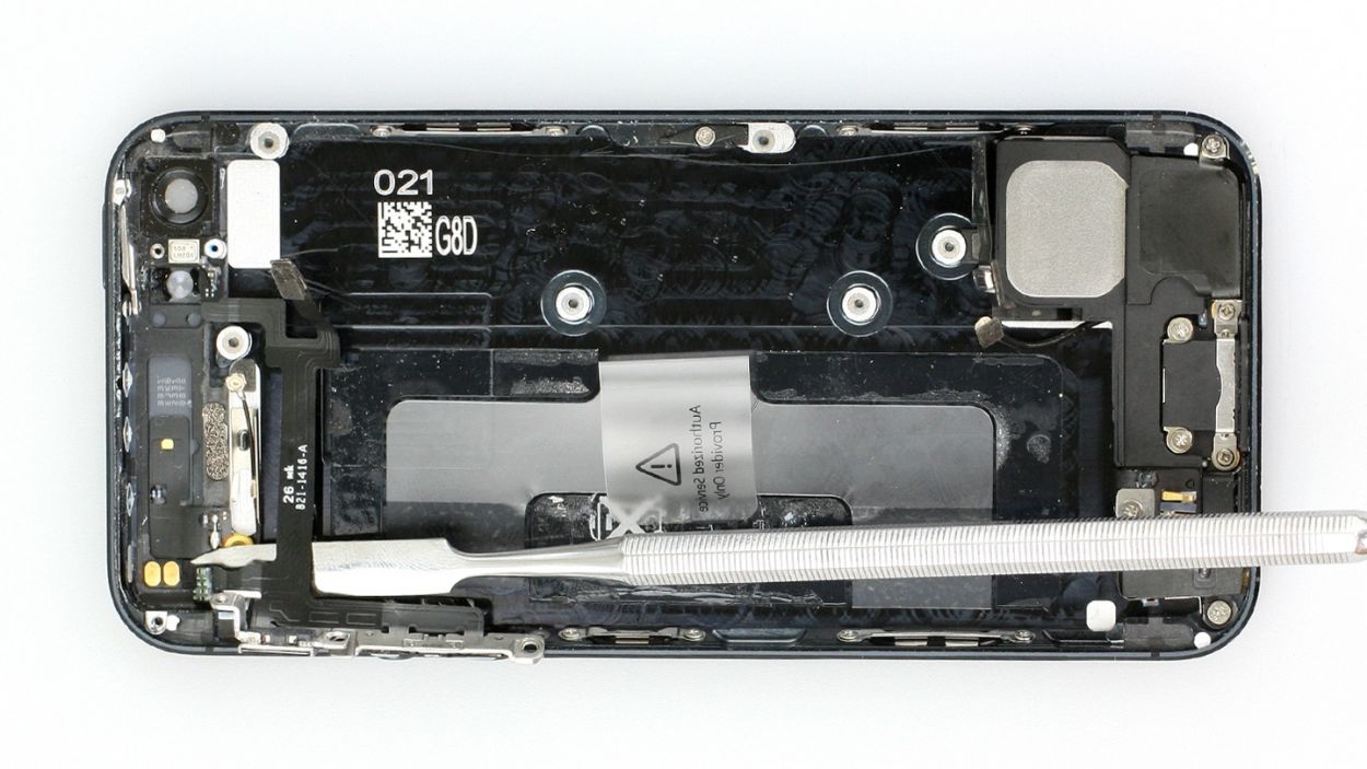
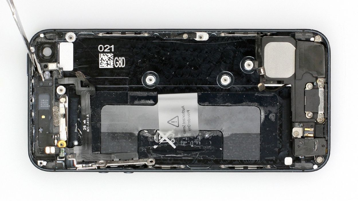
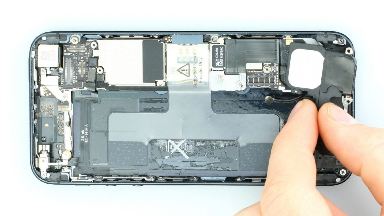
– Alright, champ, let’s get this battery out! It might be feeling a little cozy, stuck in place with some glue. Gently slide the flat end of your spudger between the battery and the logic board and give it a little lift. Remember, the logic board is super sensitive, so be nice to it! You can try lifting from the other side too if that feels better.
If it’s stubbornly refusing to budge, try using your spudger at a few different spots around the battery to loosen it. Still no luck? Grab your heat gun (or hairdryer – hey, we’re not judging!) and give the glue a little warmth. It should soften right up. If you’re still having trouble, schedule a repair with us; we’re happy to help!
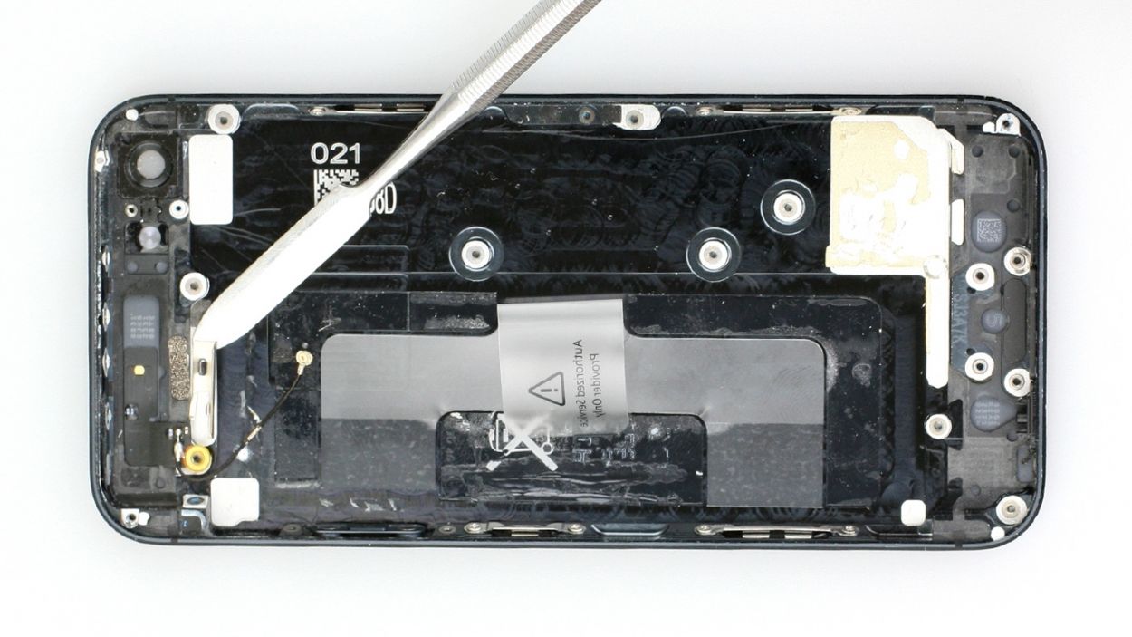
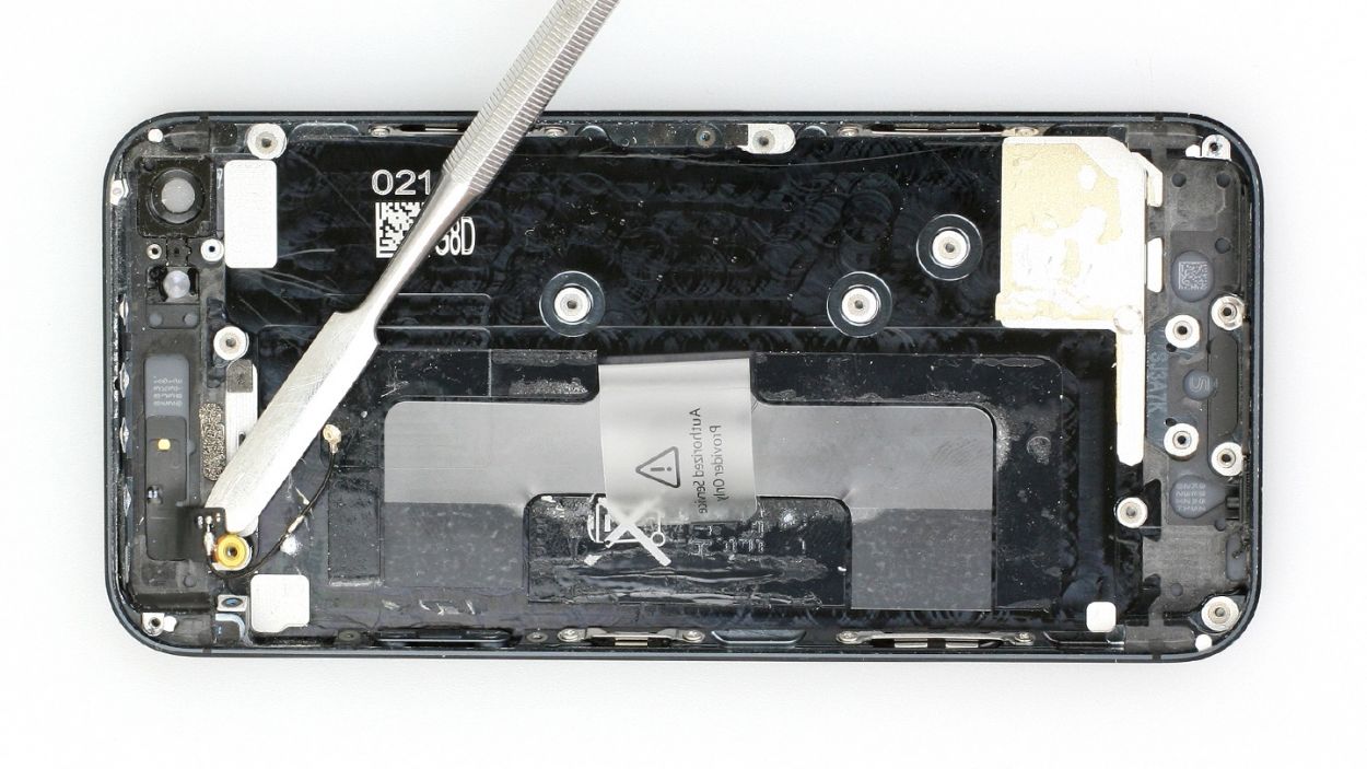
Step 6
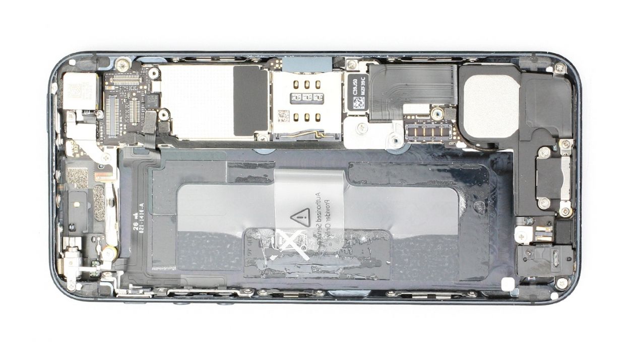
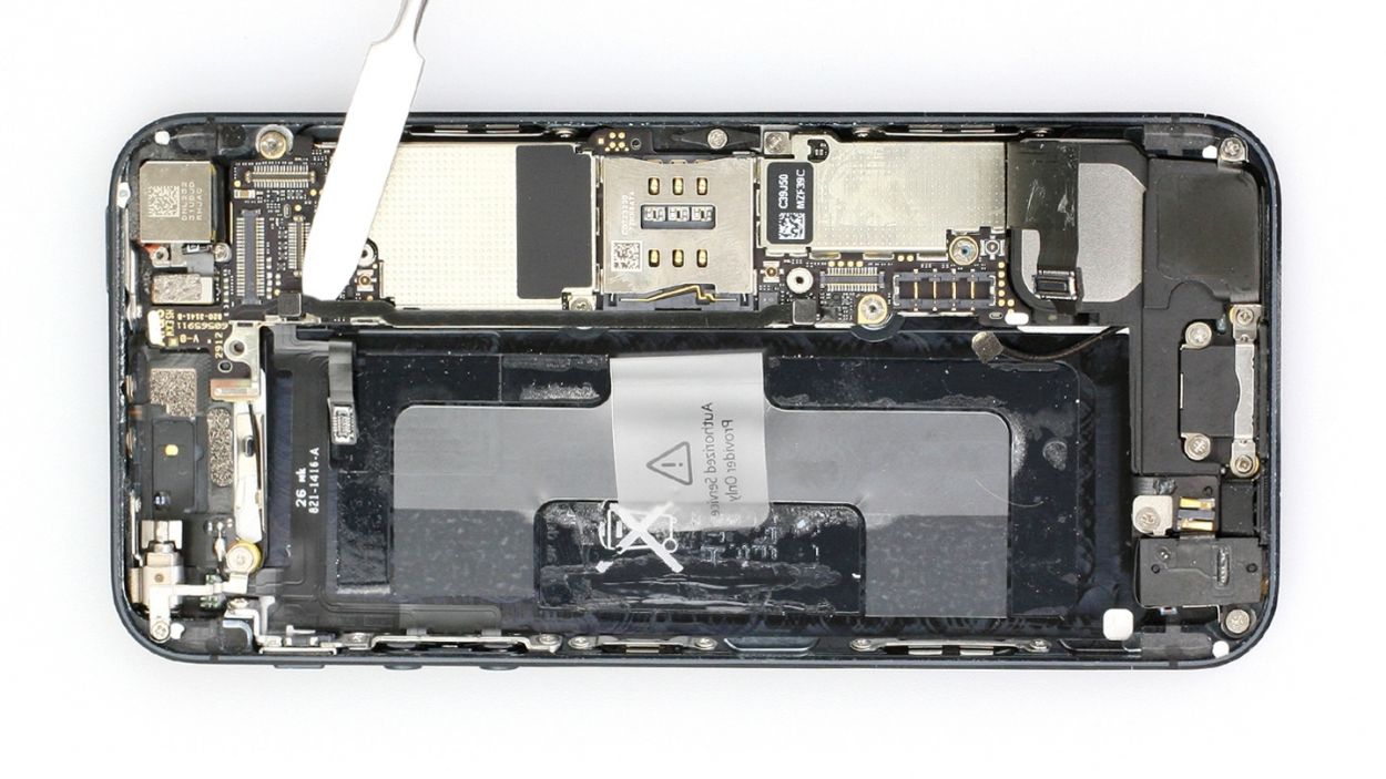
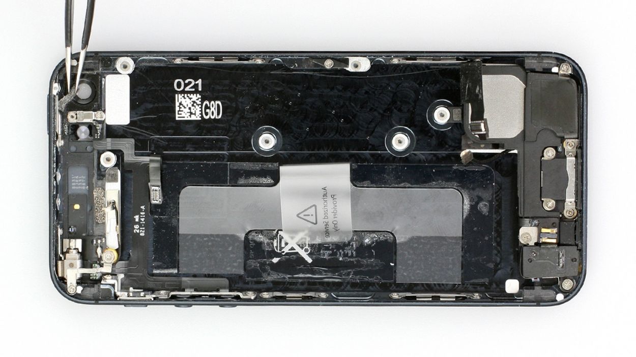
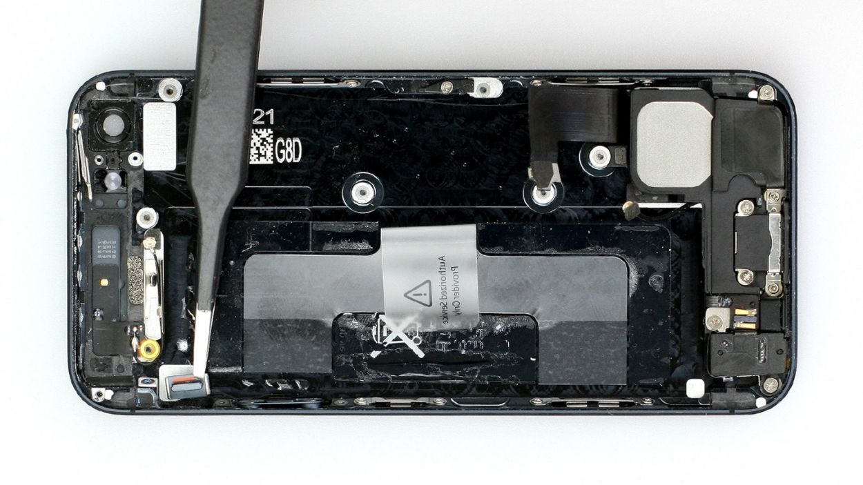
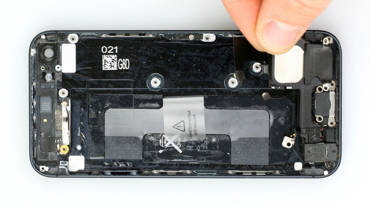
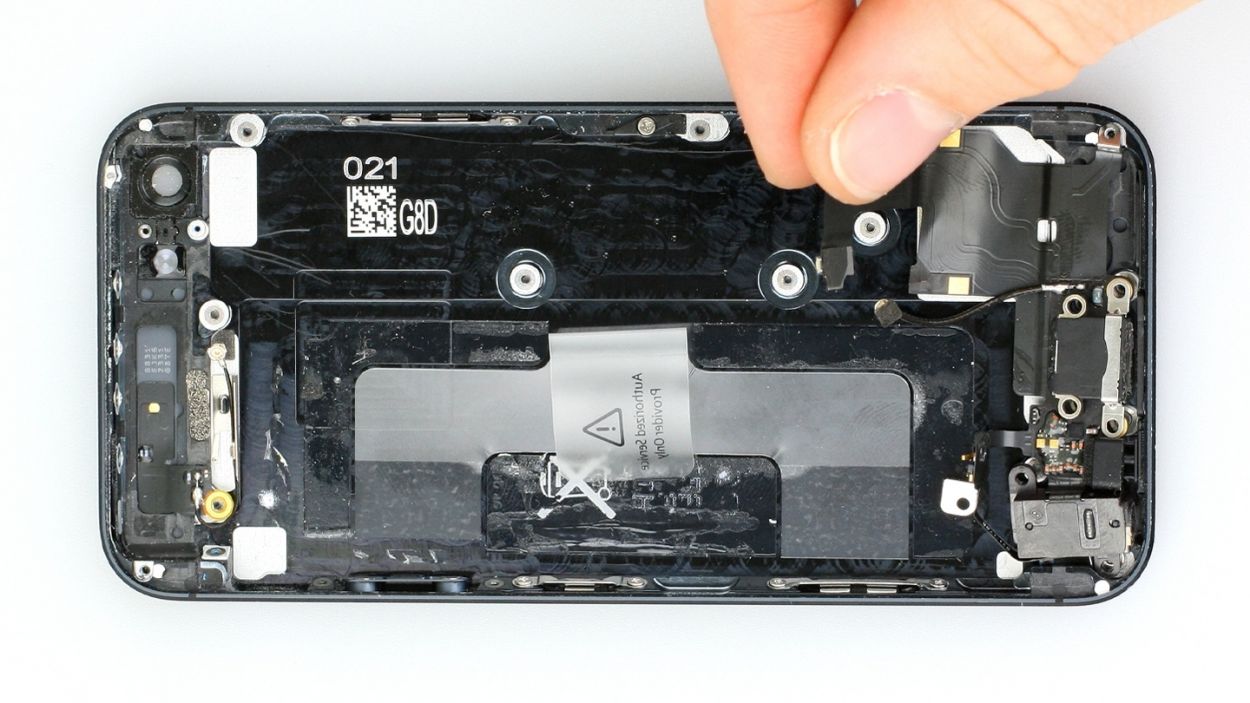
– Go ahead, fold that plastic tab with the warning like you’re tucking it in for a cozy nap, then press it down snug onto the adhesive strip. This way, it won’t be playing hide and seek during your repair.
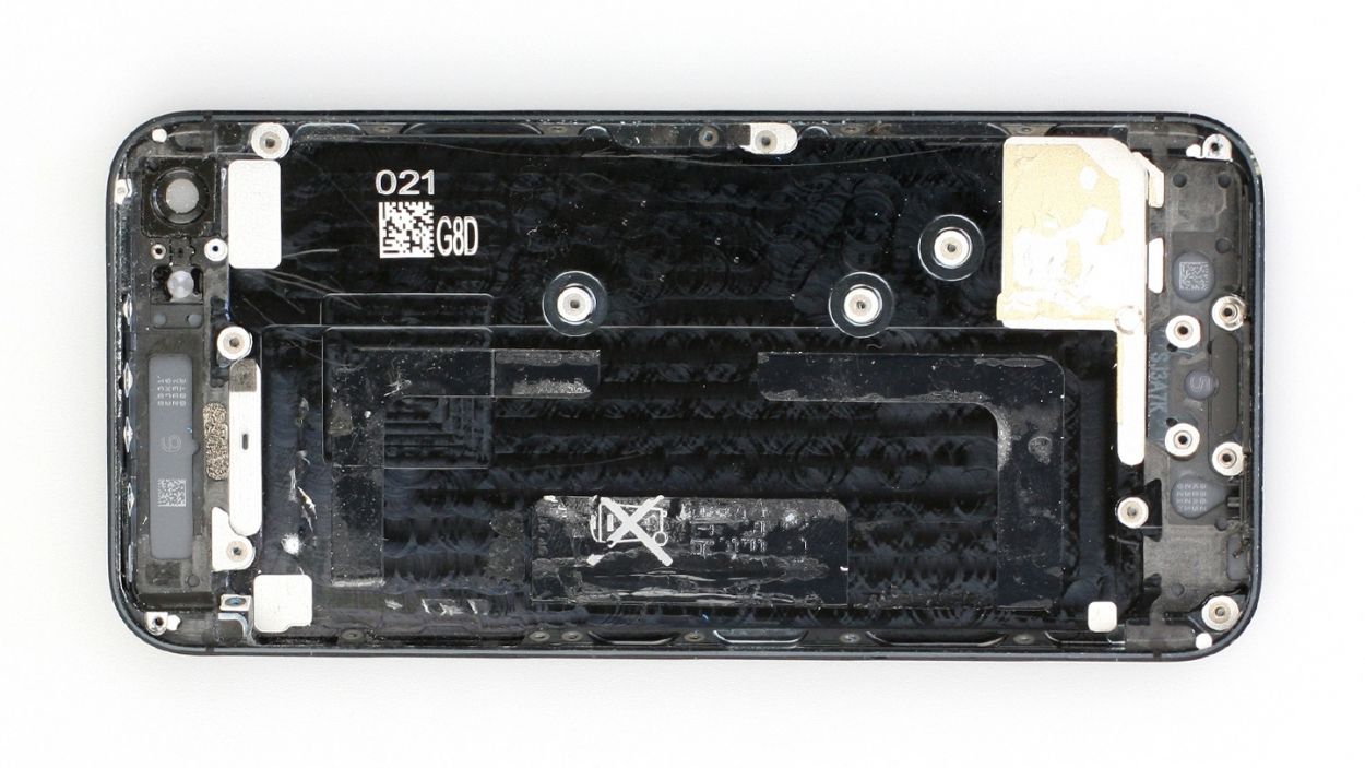
Step 7

– Ready to jazz up your repair game? Use either the SIM Tool or a paperclip to slide out that SIM card tray. Tap that SIM Tool into the tiny hole on the SIM card tray and slide it on out!
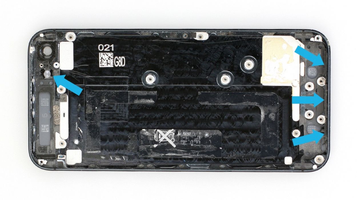
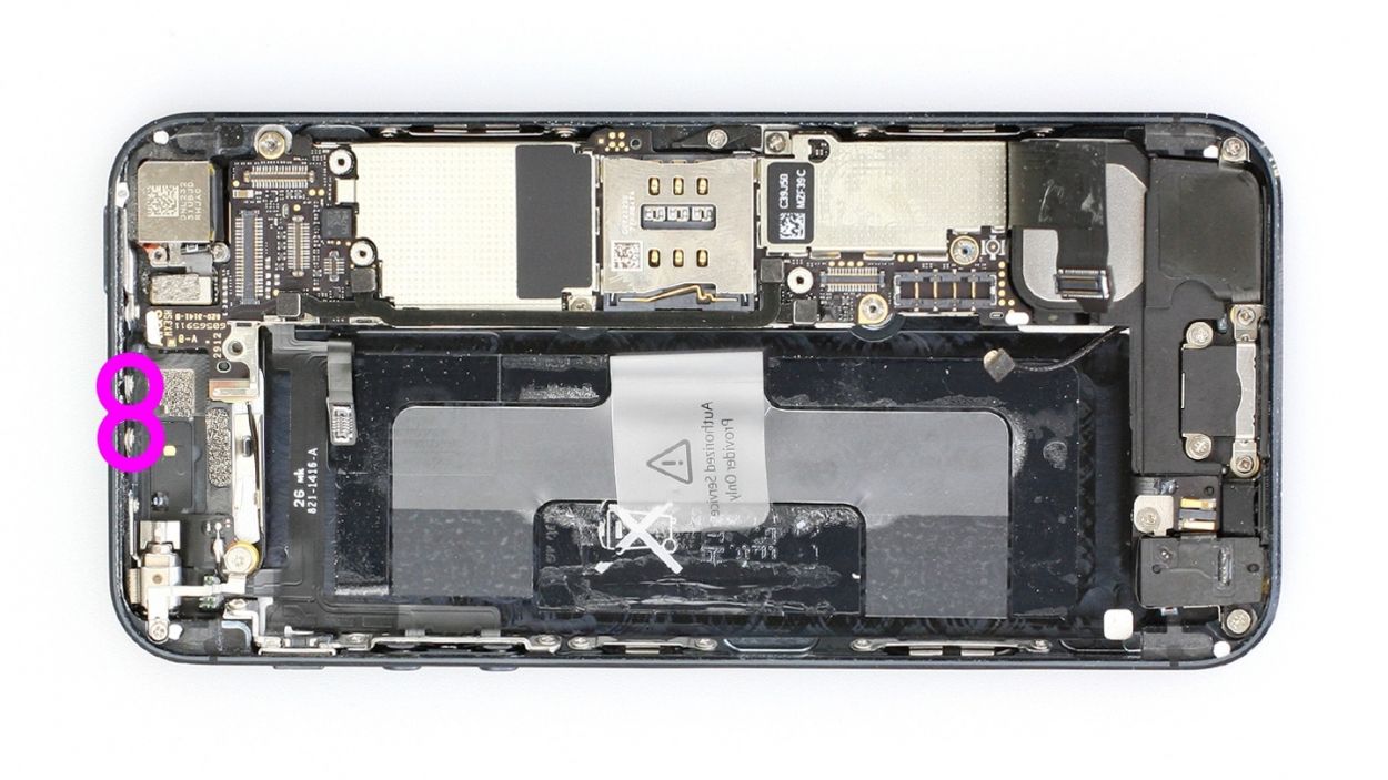
Step 8
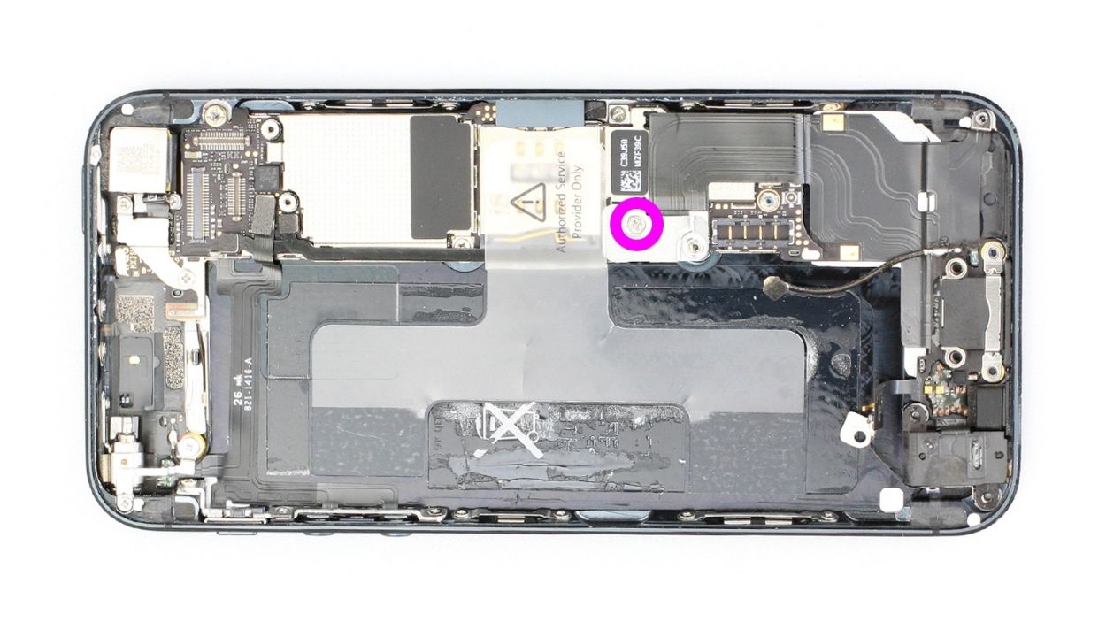
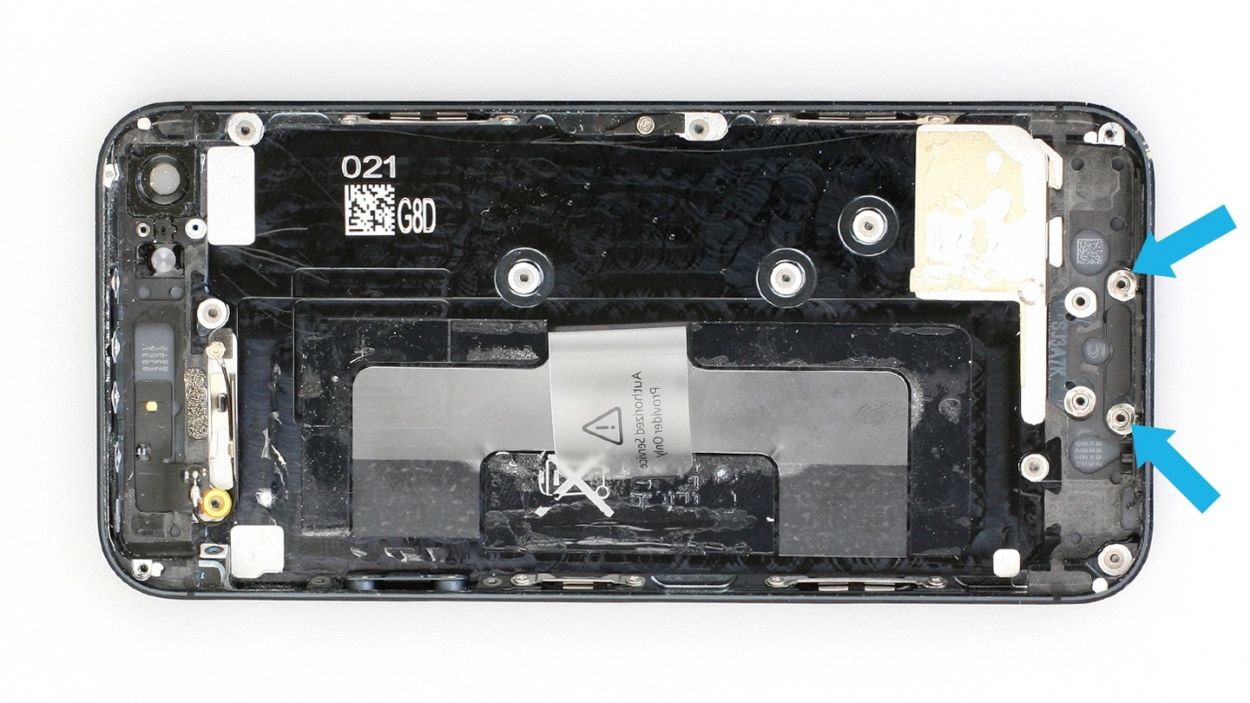
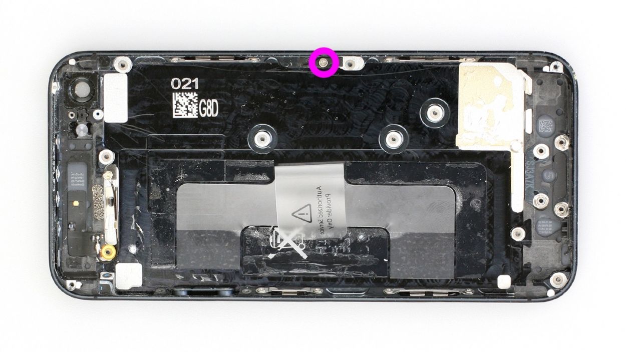
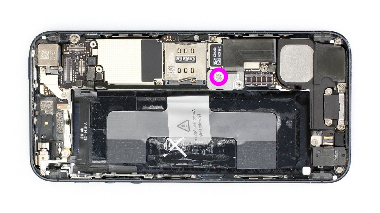
– First, let’s tackle that Phillips screw and the shiny silver cover beneath it (check out figure 1). Make sure to keep those parts cozy in the same compartment of your organizer tray. You’ve got 1 x 1.2 mm Phillips screw to keep track of!
– Next up, it’s time to disconnect the Lightning connector’s ribbon cable (see figure 2). Gently slide the pointed tip of your spudger just below the contact and lift it up. Then, with a little care, fold the cable over. Easy peasy!
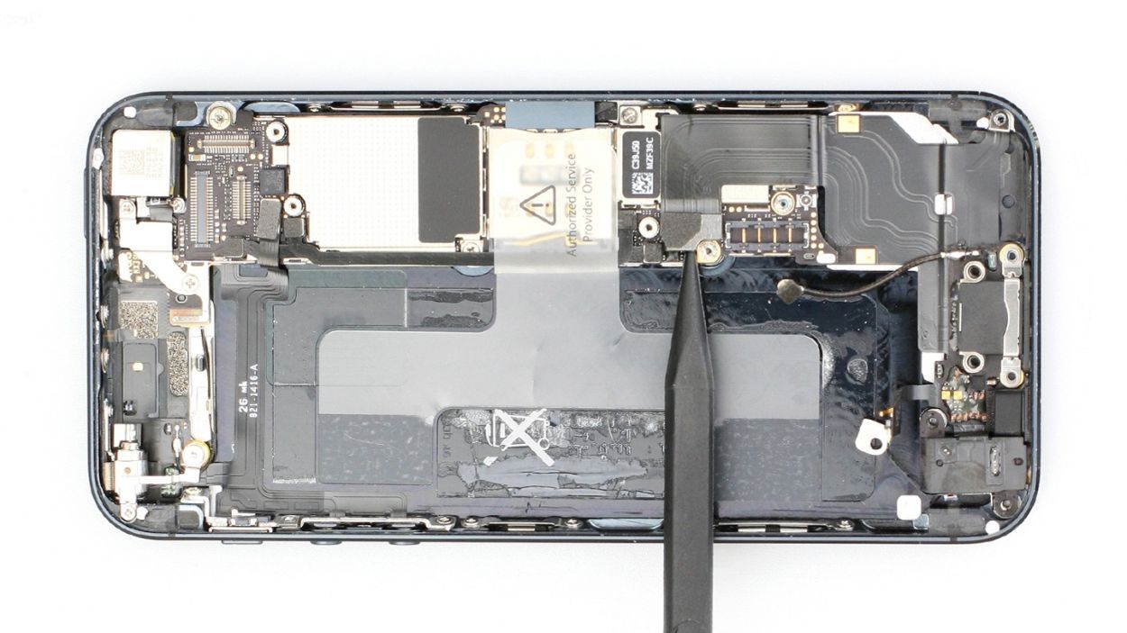
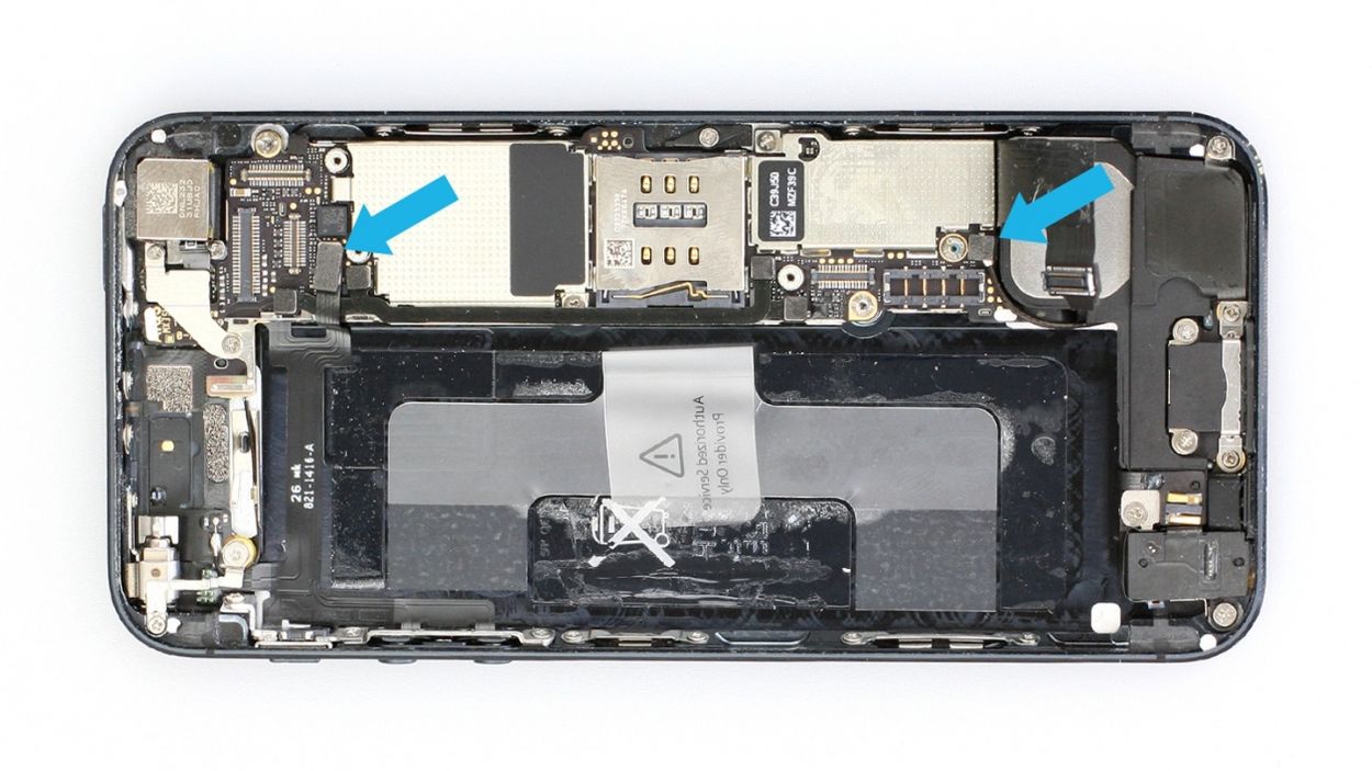
Step 9
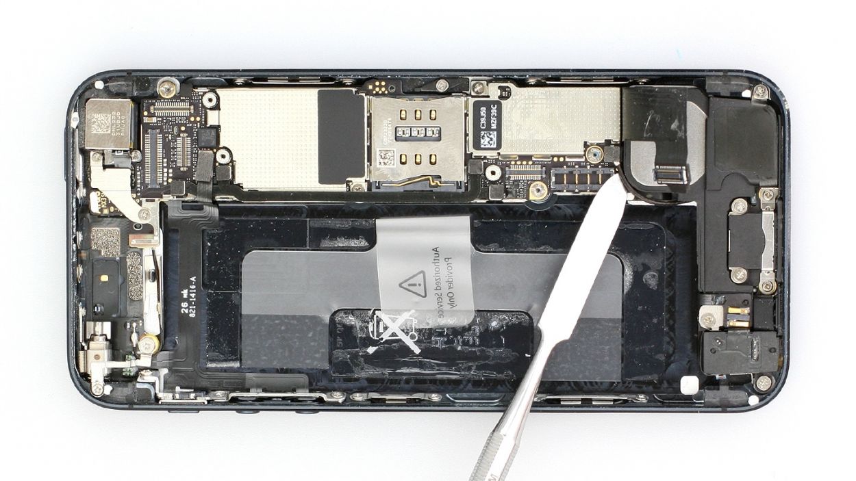
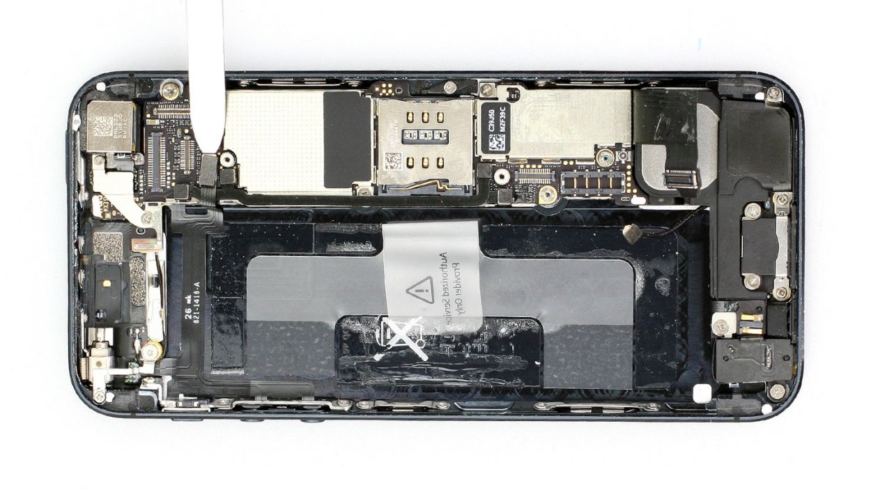
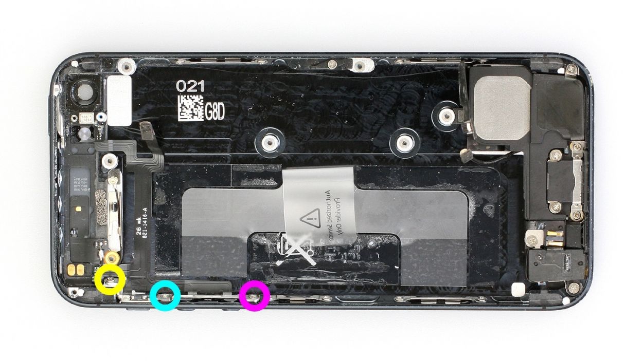
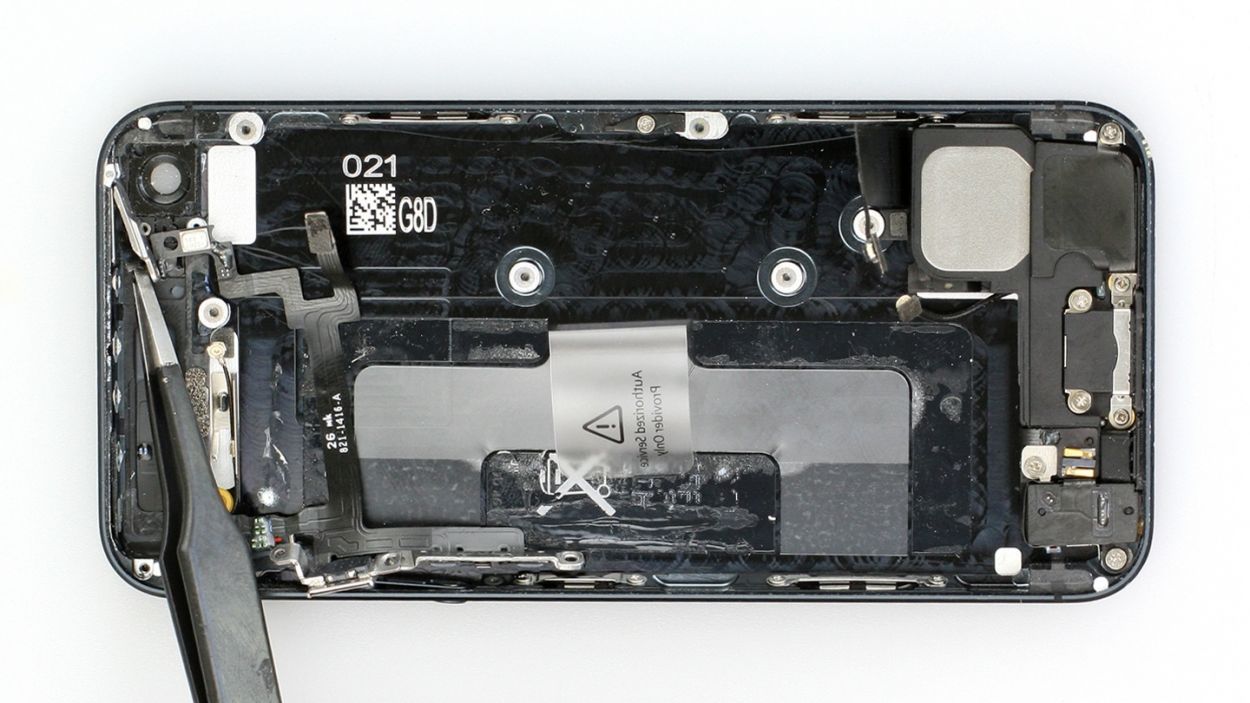
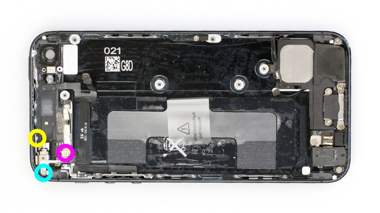
– Hey there! Time to work your magic on that antenna connector with the trusty laboratory spatula. Lift it off gently like a pro (check out figure 1)!
– Now, let’s give a big shoutout to the standby/volume cable set connector. Lift it off like a champ (see figure 2). Use the spudger or spatula to lift it up carefully, making sure to keep those resistors safe and sound on the logic board.
Step 10
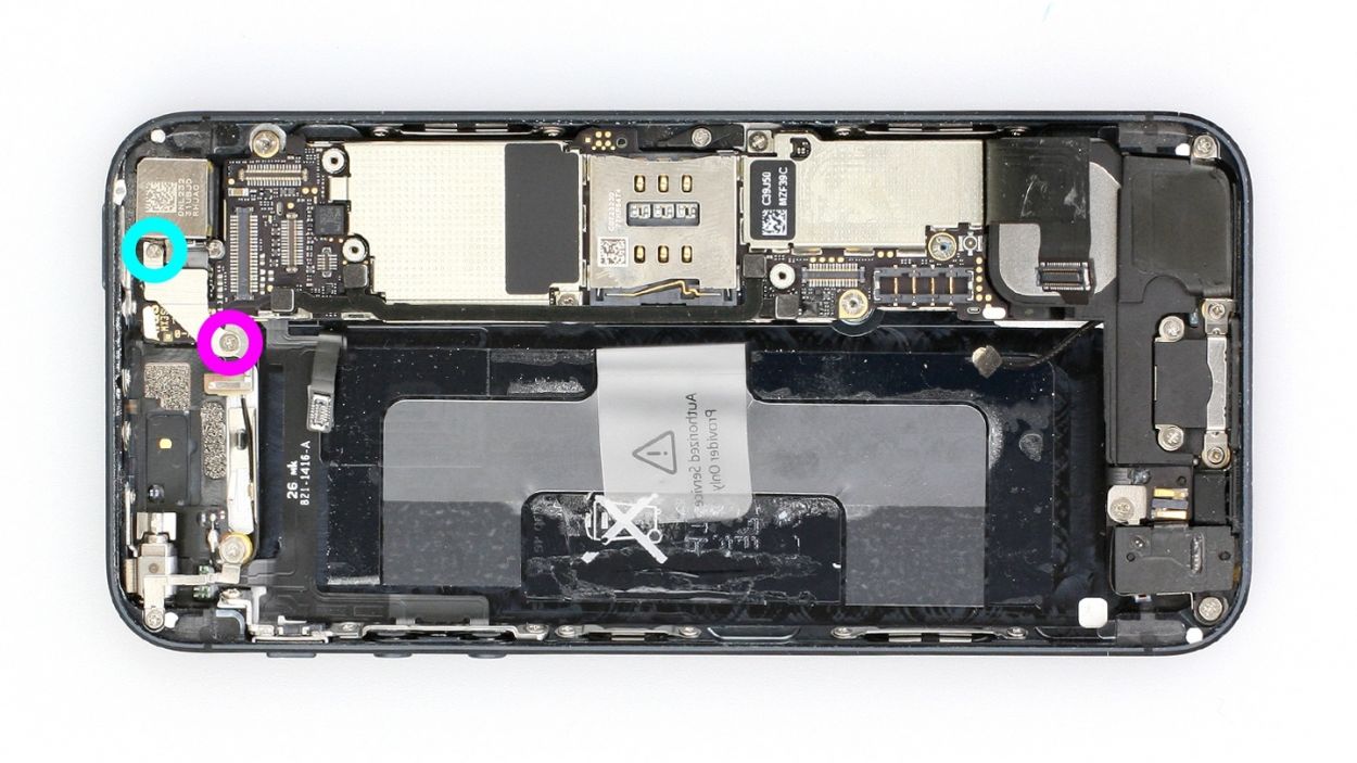
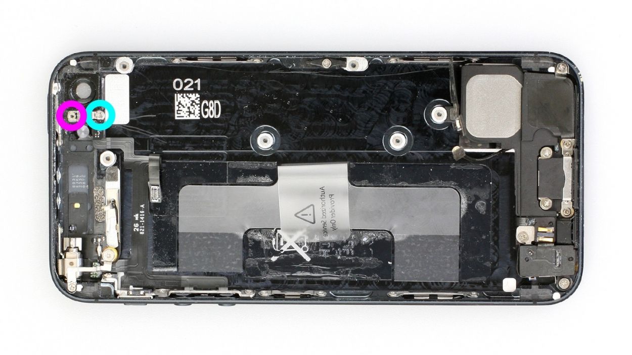
– Alright, let’s get those screws out! First, we’ll remove the two Phillips screws and the bracket hiding underneath. Don’t forget there’s another connection lurking beneath that bracket – be sure to keep track of everything!
We recommend using a parts organizer tray to keep everything neat and tidy! You’ll need to keep track of:
1 x 2.3 mm Phillips screw
1 x 1.5 mm Phillips screw
Step 11

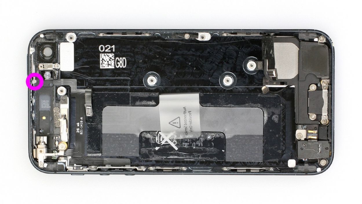
– Alright, let’s get those antenna screws outta there! Grab your Phillips screwdriver and give those two little 1.3 mm guys a gentle nudge. They’re just hanging out, ready for a new adventure!
Step 12
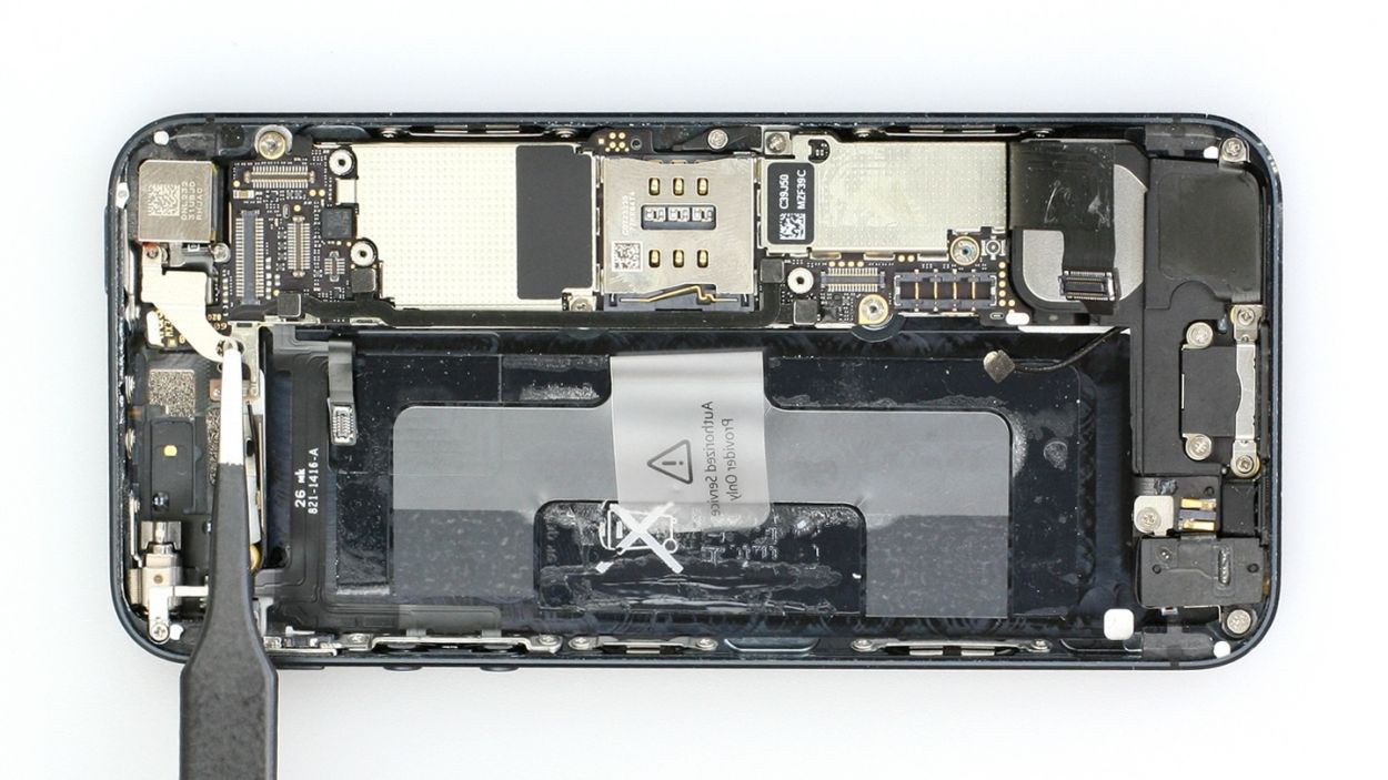
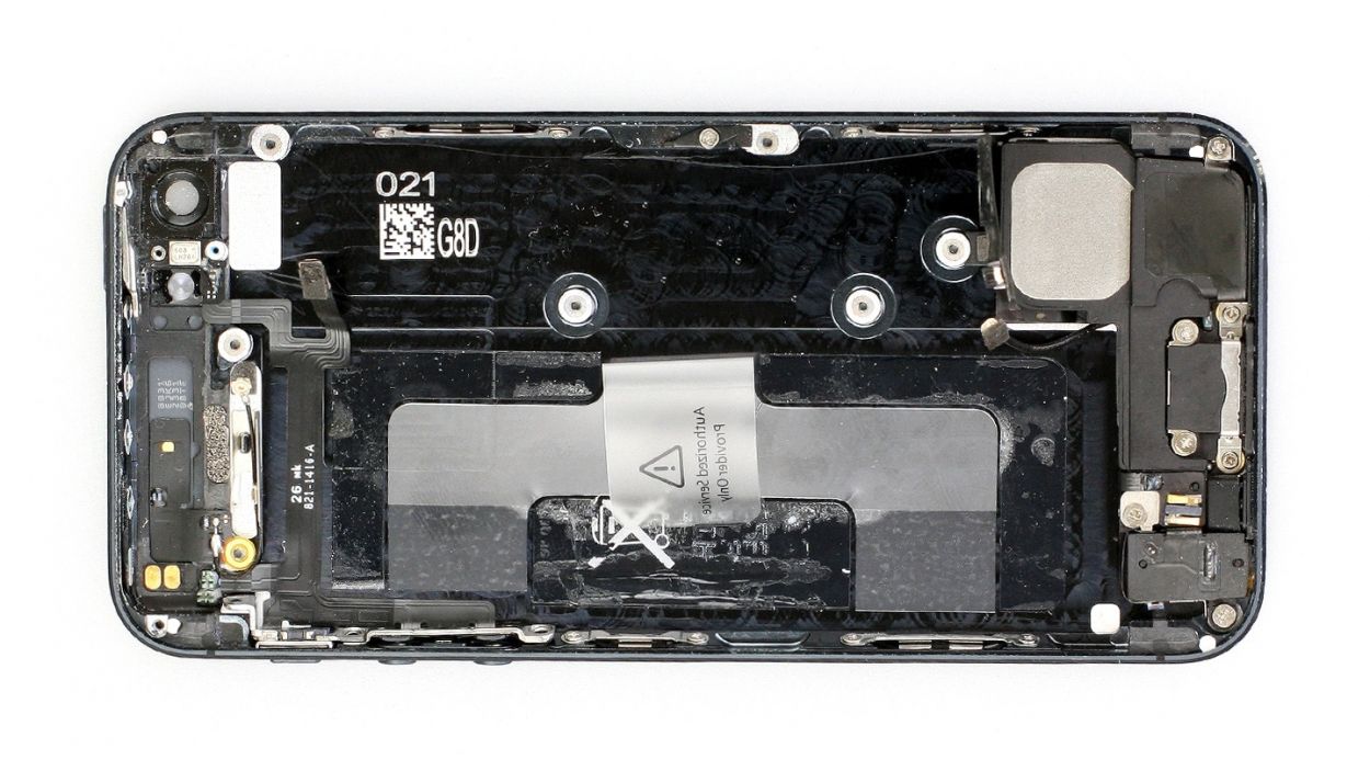
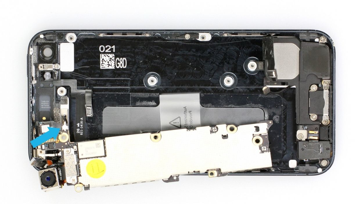
– Time to tackle those connection cables! First, gently pull out the two cables (check out figures 1 and 2 for a visual guide). Now, grab your trusty spudger or spatula and carefully slide the pointed tip just under the contact. Give it a little lift, but be super cautious not to break off any of those tiny resistors soldered onto the logic board. You’ve got this!
Step 13

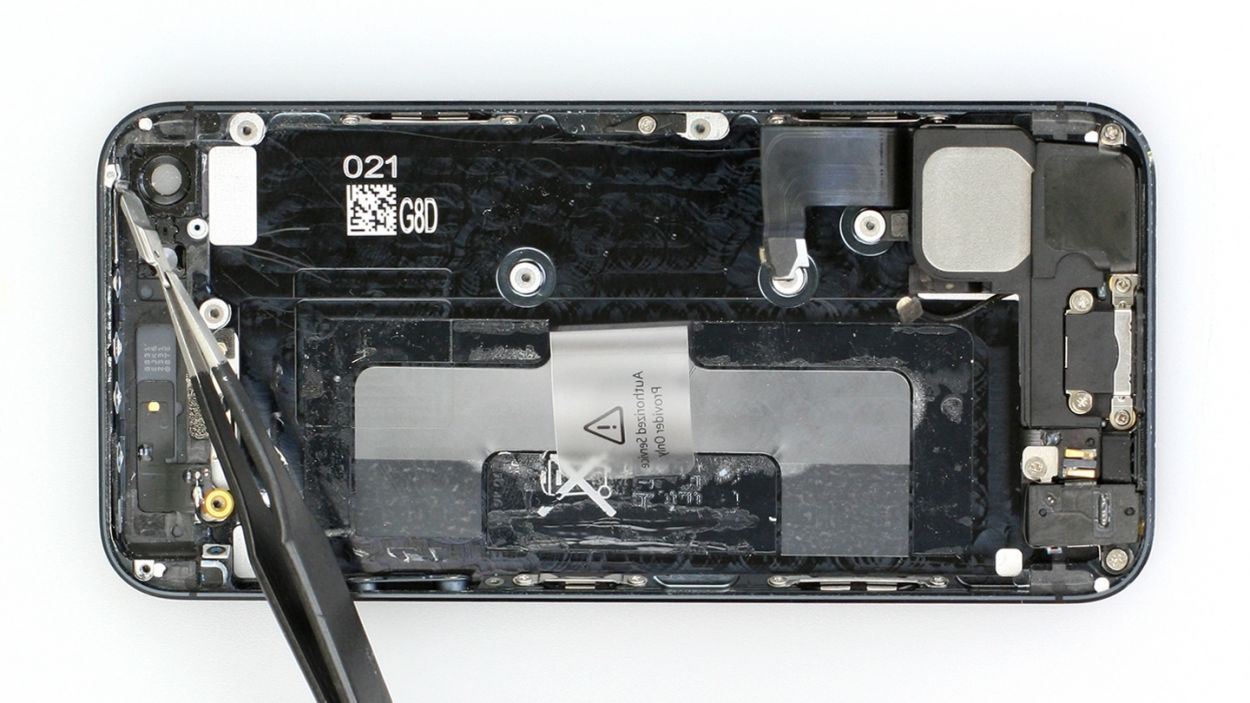
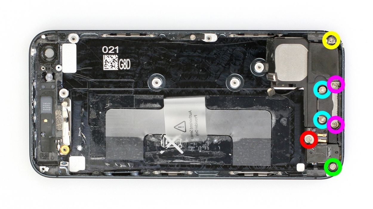
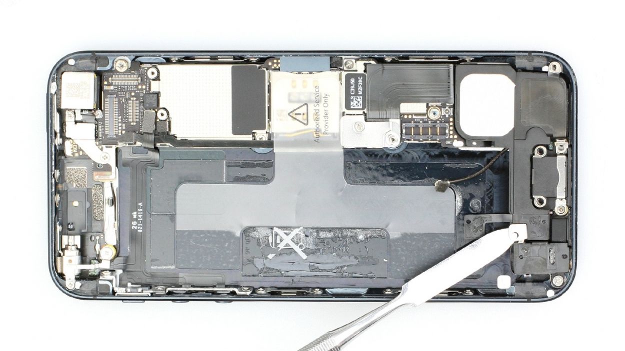
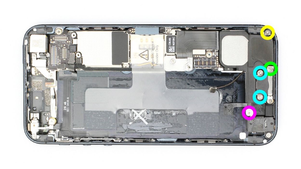
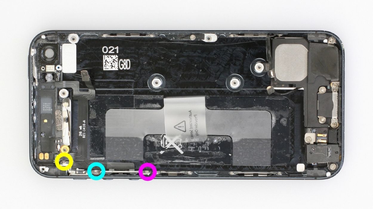
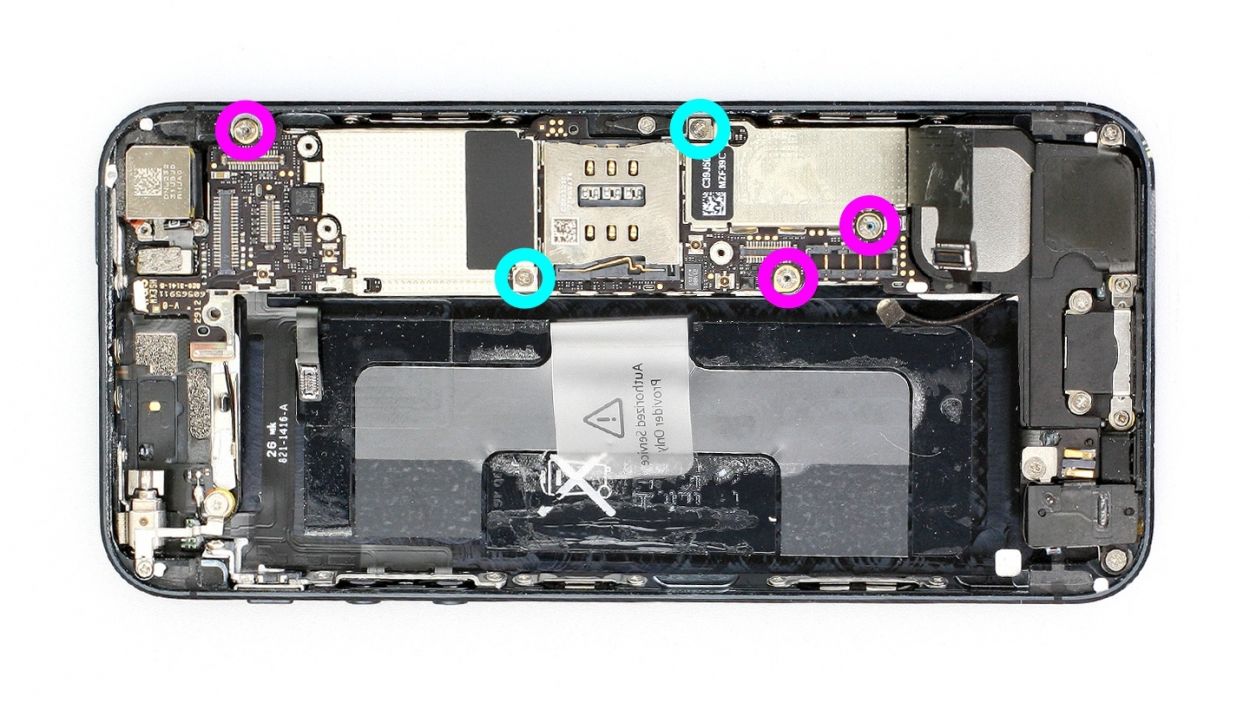
– Alright, let’s get those five screws out that are keeping the logic board snug as a bug! Check out figure 1 for a visual guide.
– Three of these screws have an internal thread, and the one next to the rear camera is a bit of a rebel – it’s not magnetic! You can use a flathead screwdriver or your trusty spatula to remove it. Make sure to keep all those screws in the same compartment of your organizer tray. You’ve got 3 x 2.7 mm Phillips/flathead screws and 2 x 2.3 mm Phillips screws to keep track of!
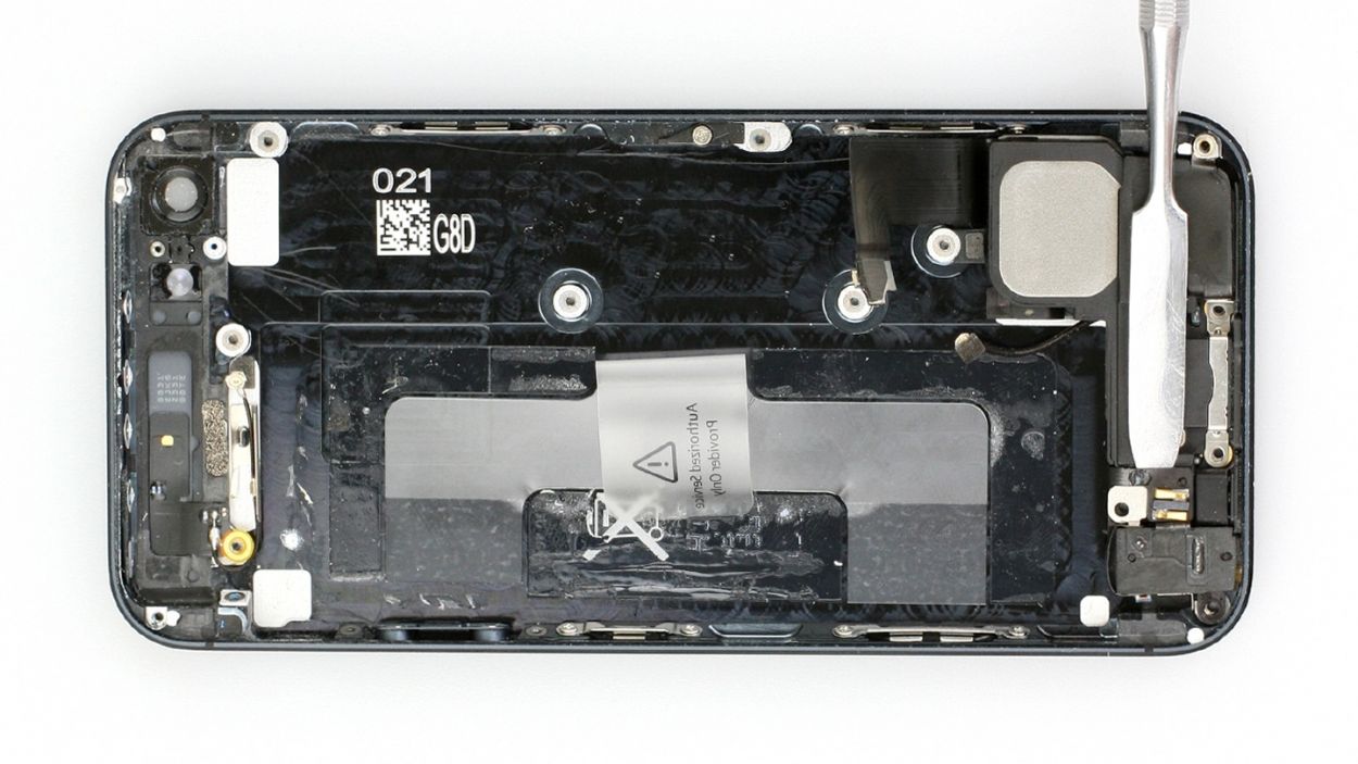
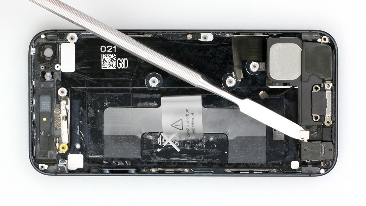
– Now, gently lift the camera flash using the laboratory spatula (see figure 2).
Step 14

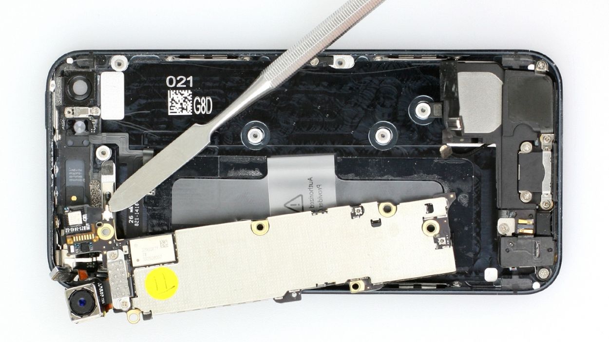
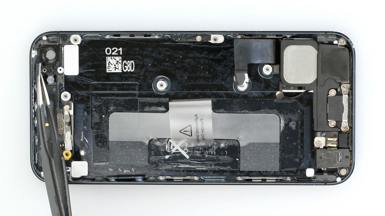
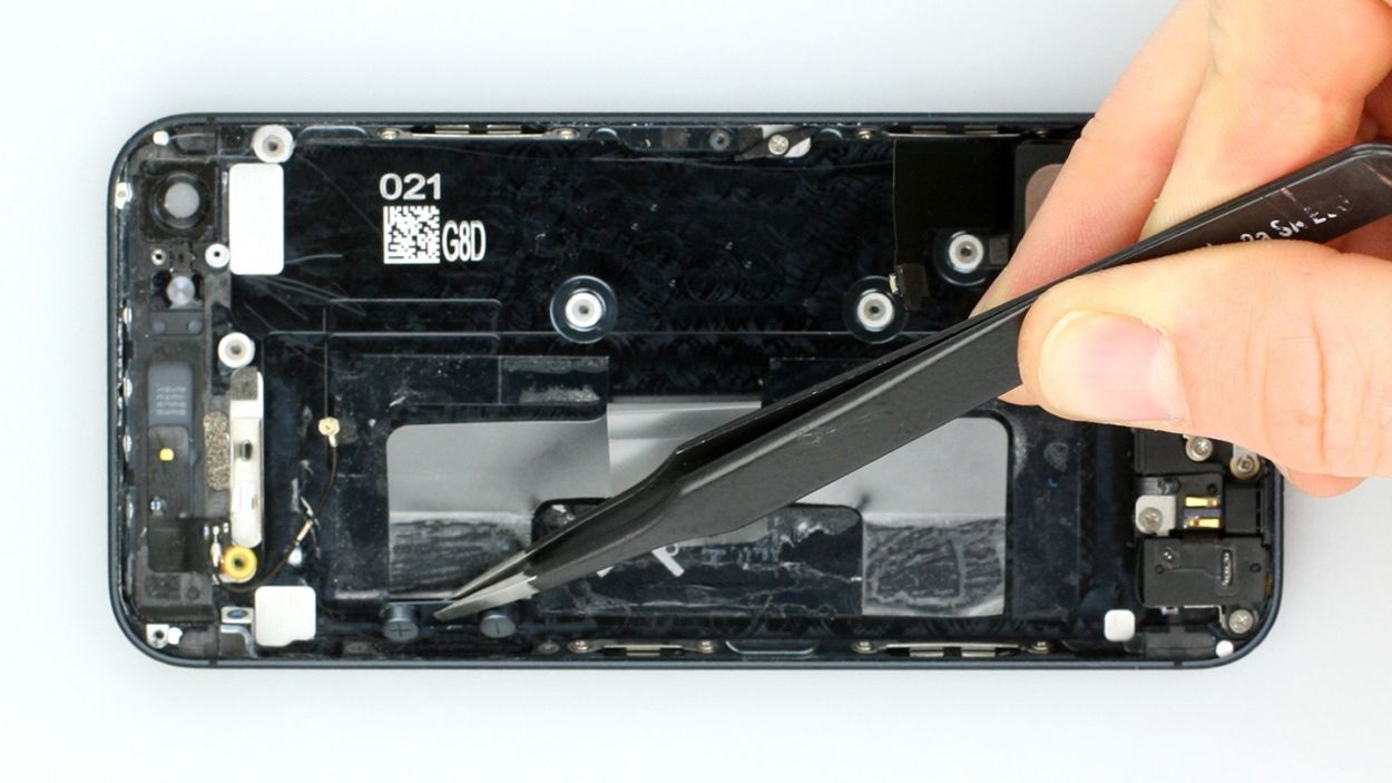
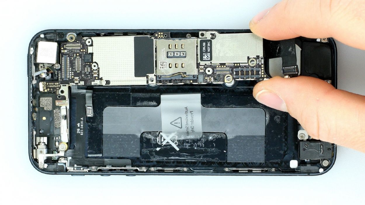
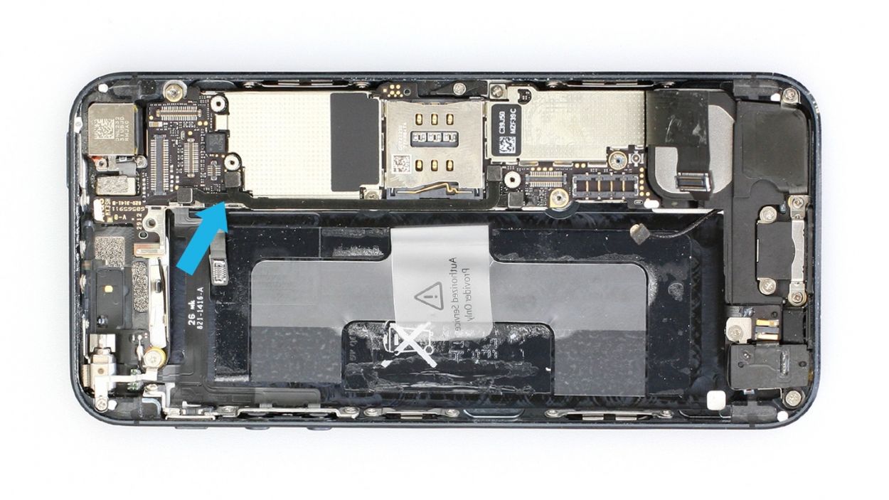
– Gently lift the logic board with your spudger (see figure 1), then give it a little twist using the plastic tab (check out figures 2 and 3). It’s like a little logic board dance!
– On the other side, use your spudger to carefully unplug the antenna connector – just a gentle tug will do! (see figure 3)
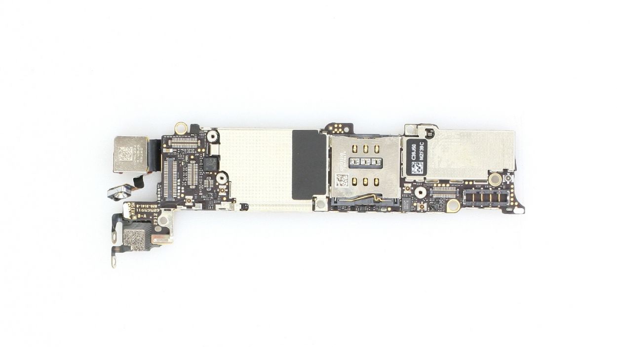
– Now, with a flourish, carefully remove the logic board. You’re doing awesome!
Step 15

– Get ready to jazz up your repair game! Peel off that foam sticker with style (check out figure 1).
– Now unscrew the Phillips screw like a pro (see figure 2). Pop the screw and foam sticker in the same cozy compartment of your organizer tray. You’ve got a cool 1 x 1.9 mm Phillips screw to keep track of!
Step 16

– Alright, time to get your hands a little dirty! Start by removing those screws and the metal bracket. Grab your trusty laboratory spatula or flathead screwdriver to tackle that sneaky screw with internal threading. Here’s what you’ve got: 1 x 2.9 mm Phillips/flathead screw and 1 x 1.6 mm Phillips screw. Happy unscrewing!
Step 17

– Unscrew the three screws that are keeping the vibration motor and its trusty support frame snug as a bug.1 x 1.8 mm Phillips screw1 x 2.4 mm Phillips screw1 x 1.5 mm Phillips screw
– Now give that vibration motor its well-deserved break and remove it gently.
Step 18
– Time to tackle those three Phillips screws in the volume and mute button bracket! Just a heads up, this bracket is glued to the cable set, so give it a gentle nudge. You’ve got this!
Step 19

– Hey there! Time to rock and roll with the repair of your device! Carefully detach the lightly glued cable set using the laboratory spatula (check out figures 1 and 2).
– Get ready to part ways with the standby button that’s stuck to the metal rocker switch (take a peek at figure 3). Now, gently separate the cable set from the rocker switch. It might be best not to remove the rocker switch, as putting it back in can be a bit of a challenge.
– Once you’ve successfully detached the cable set from the rocker switch, you can slide it out using tweezers (refer to figure 4) or simply use your fingers.
Step 20


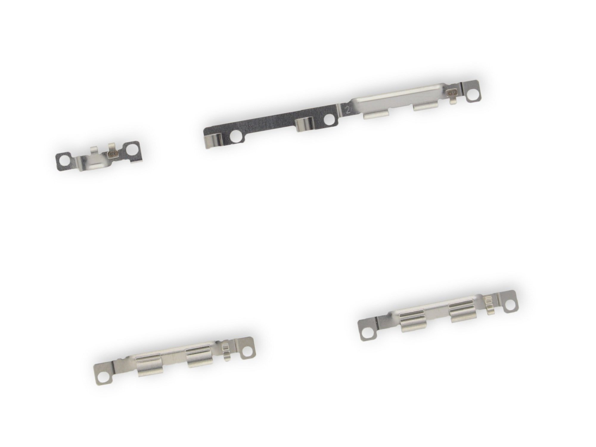
– Say goodbye to the volume, mute, and standby buttons, and don’t forget the rocker switch for that standby button – they’re ready for a new home!
– That rocker switch is hanging out on a metal peg, so if there’s no peg in your new back cover, feel free to give it a second chance! Reuse it with pride.
Step 21
– Alright, let’s tackle those five Phillips screws like a pro! Make sure to stash them in different compartments of your organizer tray so you can easily spot them later on. Here’s the lineup:
2 x 1.4 mm Phillips screw
2 x 3.1 mm Phillips screws
1 x 2.7 mm Phillips screw
1 x 2.7 mm Phillips screw
1 x 2.4 mm Phillips screw. Keep up the great work!
Step 22
– Hey there! Time to show that Home button contact cable who’s boss! Give it a gentle nudge with the trusty laboratory spatula to set it free (check out figure 1).
– Peel off the silver cover that’s holding onto the cable (check out figure 2). It’s like unwrapping a little gift!
– And now, it’s time to bid farewell to the speaker (see figure 3). Off it goes, ready for its next adventure!
Step 23
– Gently wiggle that ribbon cable free with your fingers (check out figure 1). While you’re at it, grab your spatula or spudger to help detach the Lightning connector, headphone jack, and microphone. Teamwork makes the dream work!
– Keep an eye on those tiny washers hiding beneath the cable set – we wouldn’t want them to go missing (see figure 2)!
Step 24
– Time to get that ejector lever out! Unscrew the Phillips screw and gently remove the lever. You’ve got 1 x 2.0 mm Phillips screw to keep track of!
Step 25
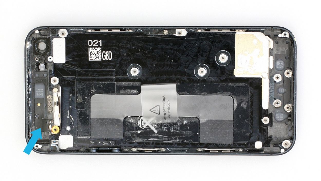
– Time to jazz up your repair game! Say goodbye to the silver rail by gently sliding in the laboratory spatula and detaching it from the back cover (check out figure 1).
– Ready to rock and roll? It’s time to show some love to the antenna ribbon cable. Glide in the laboratory spatula below the cable and unhook it from the back cover (check out figure 2). You’ve got this!
Step 26

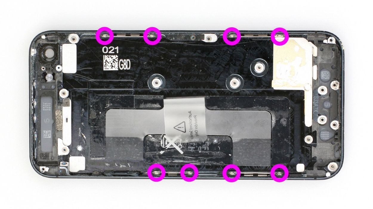
– Alright, let’s tackle those screws with style! Remove the two Phillips screws holding each of the four retaining brackets in place. Make sure to stash those screws in the same cozy compartment of your organizer tray. You’ve got 8 x 1.6 mm Phillips screws to keep track of!
Step 27
– Get ready to jazz up your repair game! It’s time to gently fold that plastic tab with the warning like you’re tucking it in for a cozy nap, then press it down snug onto the adhesive strip. This way, it won’t be playing hide and seek during your repair.
– Feeling like a rockstar? You may need to hold onto other bits of your old back cover for the new one. Keep up the great work!
Step 28
– Go ahead and stick that plastic tab onto the new back cover and give it a little fold. If you’re feeling like a rebel, you can totally wait to do this until after you’ve installed the battery!
Step 29
– Let’s get those four brackets attached! Use your Phillips screwdriver to secure them with the 8 x 1.6 mm Phillips screws. You’ve got this!
Step 31

– Let’s get that ejector lever in place! Use your Phillips screwdriver to attach it. Remember, the top part of the ejector lever should be positioned to the left of the SIM card slot. You’ve got 1 x 2.0 mm Phillips screw to keep track of!
– Now, give that SIM card tray a little test! Can you push it in and out smoothly? You’re doing great!
Step 32

– Alright, let’s get that Lightning connector in there (check out figure 1)! Just make sure those little washers are snug on the thread.
– Now, gently push the microphone’s rubber seal into that tiny black groove. It’s all about making sure the Lightning connector and audio jack fit perfectly against the frame. You’re doing great!
Step 33
– Give that speaker a little twirl to place it back in its original spot (see figure 1).
– Next up, pop on that shiny silver cover attached to the cable (see figure 2). It’s like putting on a fashionable accessory!
– Now it’s time to secure those Phillips screws once more (see figure 3). Here’s what you’ll be dealing with: 1 x 2.8 mm Phillips screw, 2 x 3.3 mm Phillips screws, 1 x 1.4 mm Phillips screw, and 1 x 2.9 mm Phillips screw. You got this!
Step 34


– Time to put those volume, mute, and standby buttons back where they belong, along with the standby button’s rocker switch! Just a quick reminder: the rocker frame for the standby button should be facing downward. And hey, double-check that you’re inserting the volume button the right way!
Step 35
– Time to jazz up your repair game! Securely attach that standby button to the metal rocker switch again (check out figure 1). It’s a bit tricky, but you’ve got this! If it feels like a challenge, try removing the rocker switch first and then sticking the standby button back on.
– Let’s connect the vibration switch and volume controller back to their original spots (check out figure 2).
– When you’re setting up the vibration rocker switch, ensure that the vibration switch is facing downward (you’ll spot the orange stripe along the frame). This little trick makes it easier to connect the button to the rocker switch correctly (refer to figure 3).
– Next up, tighten the screws on the volume and mute button bracket (see figure 4). You’ve got 1 x 1.7 mm Phillips screw, 1 x 1.8 mm Phillips screw, and 1 x 1.9 mm Phillips screw to handle. You’re doing great!
Step 36
– Give those three Phillips screws a little pep talk before securing the vibration motor and its loyal support frame. You’ll need 1 x 1.8 mm Phillips screw, 1 x 2.4 mm Phillips screw, and 1 x 1.5 mm Phillips screw to keep things in place.
Step 37

– Let’s get that metal bracket on there and secure it with the screws (check out figure 1). You’ll need: 1 x 2.9 mm Phillips/flathead screw and 1 x 1.6 mm Phillips screw.
– Next up, fasten the Phillips screw on the standby switch (see figure 2). Just a heads up, the rocker frame for the standby button should be facing upward during this step. You’ll need 1 x 1.9 mm Phillips screw.
– Finally, don’t forget to attach that foam sticker (see figure 3).
Step 38
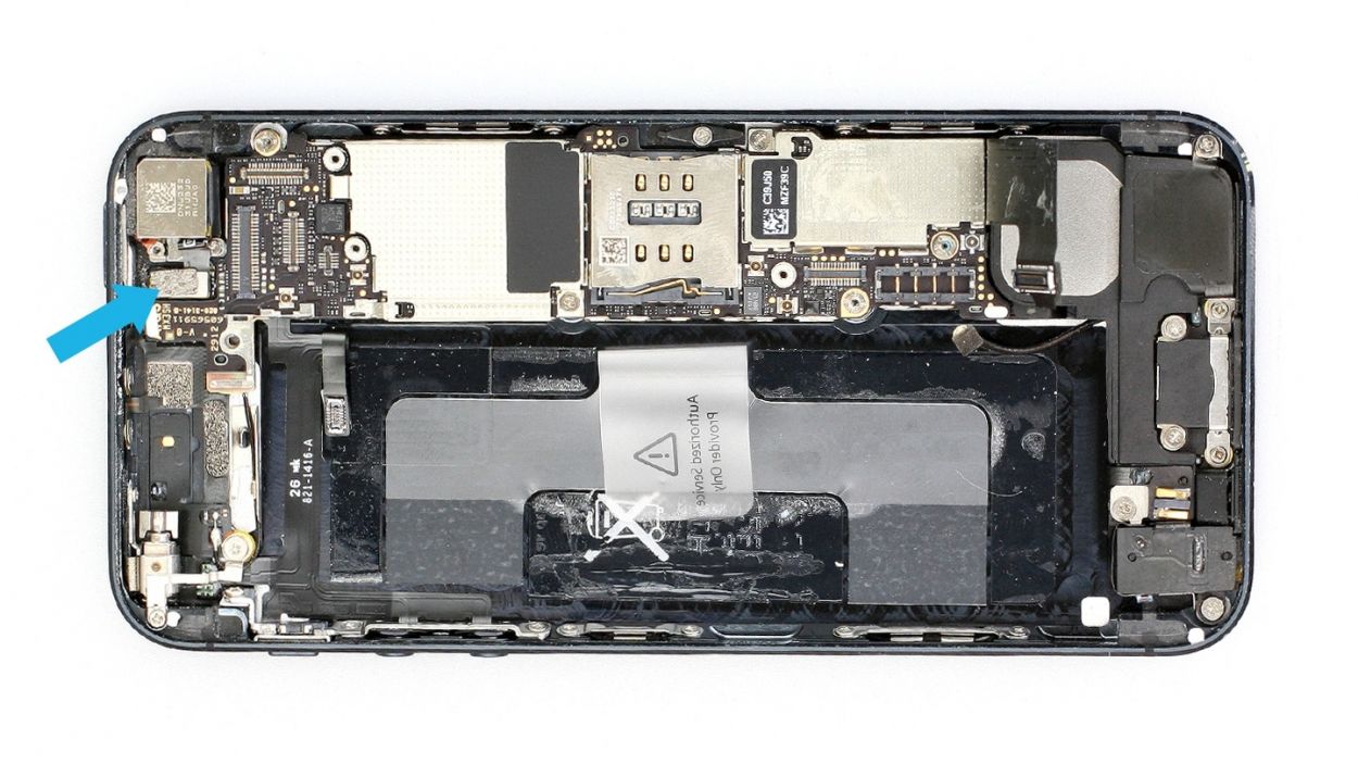
– Reconnect the WLAN antenna connector to the logic board (check out figure 1) and gently place the logic board back in its cozy spot (see figure 2). Use figure 4 to make sure your logic board is snug as a bug in a rug.
– Pop in the camera flash (see figure 3).
– Now, let’s screw in all five screws that keep the logic board secure (see figure 4). You’ve got 3 x 2.7 mm Phillips/flathead screws and 2 x 2.3 mm Phillips screws to keep track of!
Step 39
– Alright, let’s reconnect those cables! Make sure those connectors are snug as a bug in a rug – no loosey-goosey connections here!
Step 40
– Alright, let’s give those antenna screws a little love tap! Grab your trusty Phillips screwdriver and gently secure those two 1.3 mm screws. They’re just hanging out, ready for their next adventure!
Step 41

– Alright, let’s get this bracket attached! Grab your Phillips screwdriver and pop in those two screws. It’s a 2.3 mm and a 1.5 mm – easy peasy!
Step 42
– Reconnect the antenna connector and the standby/volume cable set connector like a pro (check out figure 1).
– Next, let’s get that ribbon cable connected! Gently place the cover over it and secure it with a screw (see figure 2). You’ve got this with just 1 x 1.2 mm Phillips screw!
Step 43
– Go ahead and fold that plastic tab with the warning like you’re tucking it in for a cozy nap, then press it down snug onto the adhesive strip. This way, it won’t be playing hide and seek during your repair.
Step 44

– Time to jazz up your repair game! Let’s get that battery back in the iPhone and snug it up close to the logic board like it’s getting a warm hug.
– Give that battery connector a satisfying click back into place. It’s like putting the last piece of a puzzle in its spot.
– Now, it’s cover time! Pop that cover on and screw it in. How about a high-five for those 1 x 1.8 mm Phillips screw (funnel head) and 1 x 1.7 mm Phillips screw? They’re your trusty sidekicks in this repair journey!
Step 45

– Alright, let’s reconnect those connectors (see figure 1)! Sometimes the LCD connector gets a little shy when you’re connecting the touchscreen one. Don’t worry, we’ve got you covered. Make sure the LCD, touchscreen, front camera/sensor, and earpiece are all hooked up.
– Time to reattach the battery connector and put the cover plate back on – it’s like giving your iPhone a warm hug!
– Once those connectors are snug, fire up your iPhone and check that the LCD, touchscreen, proximity sensor, front camera, and earpiece are all working like champs. If you’re having trouble with any of these, check out our handy troubleshooting guide!
– Now, let’s attach that cover and screw it in place (see figure 2). You’ll need 2 x 1.2 mm Phillips screws and 1 x 1.7 mm Phillips screw (the 1.7 mm screw is not magnetic, so be extra careful with it!).
– Gently fold down the screen, making sure the edge with the cables clicks into place. Then, carefully press the screen towards the Home button until it’s perfectly seated in the frame (see figure 3). You’re a repair rockstar!
Step 46
– Alright, let’s get those two pentalobe screws at the bottom of the enclosure all snugged up! They’re just hanging out next to the Lightning connector, one on each side. Don’t forget to keep them cozy in the same compartment of your organizer tray. You’ve got 2 x 3.6 mm pentalobe screws to keep track of!
Step 47

Uh oh! Pulling the battery out makes your iPhone’s clock think it’s 1970. No worries, though! Just sync it with iTunes or your Wi-Fi network to set the time. Otherwise, you might have trouble connecting to your cellular network. It’s a quick fix, and then you’re back in action!
– Synchronize your iPhone with iTunes or connect to a WLAN network and wait until the time is set.
– Remove the SIM tray with the SIM card and reinsert it.
– Activate airplane mode on the device and then deactivate airplane mode.