How to Replace iPhone 6 Front Camera Sensor Cable Guide
Duration: 30 min.
Steps: 13 Steps
In this guide, we show you how to replace your iPhone 6’s defective front camera/sensor cable. You need this repair if the front camera isn’t working, the aperture doesn’t open, or your pictures are blurry.Even if your screen no longer goes dark when you’re talking on the phone, replacing this cable will fix the problem.Also replace the cable if your microphone no longer works for videos or FaceTime.
Step 1
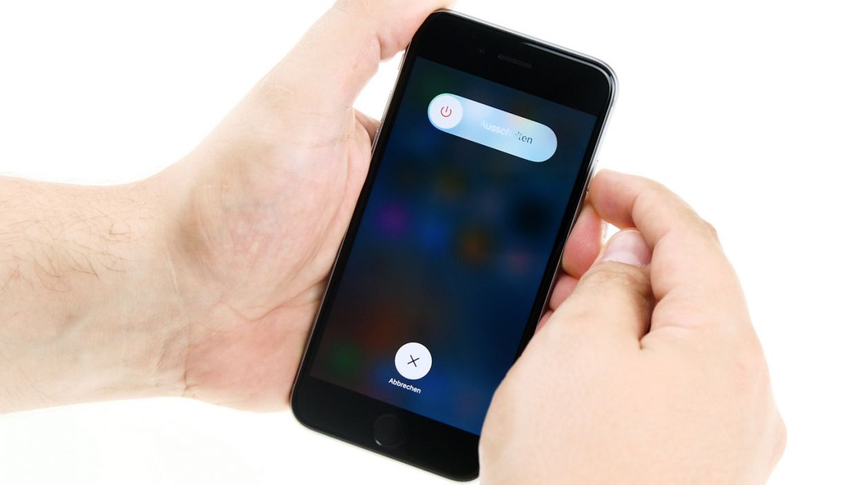
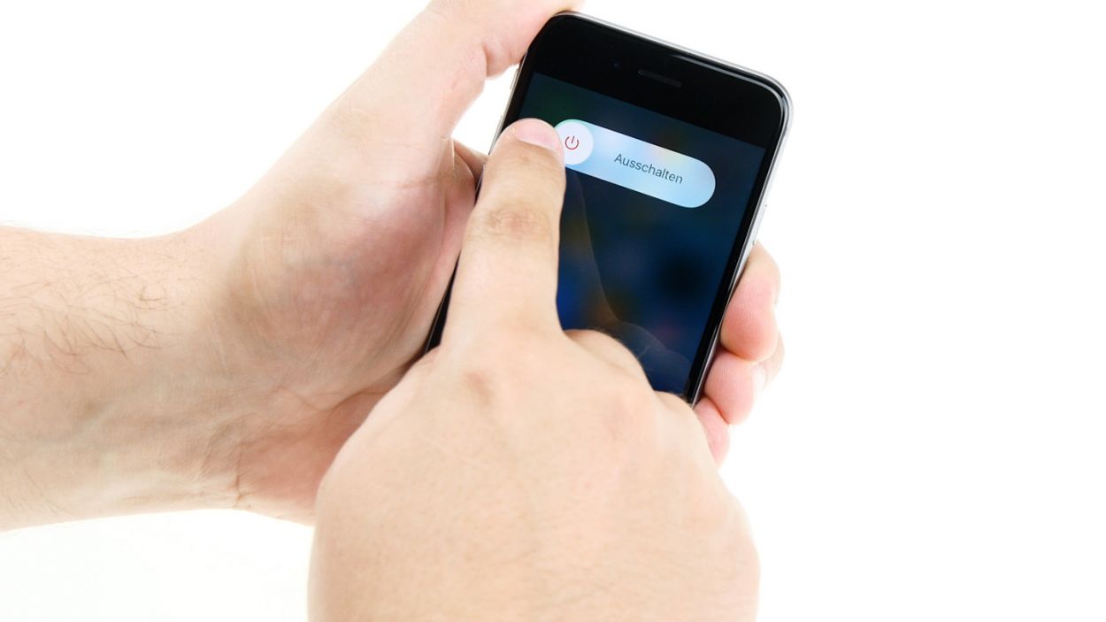
– First things first, power down your iPhone 6 completely to keep it safe during the repair process.
– Give that standby button a good press for about three seconds until the slider pops up.
– Swipe it away to fully shut down your iPhone. This might take around ten seconds, so hang tight!
Step 2
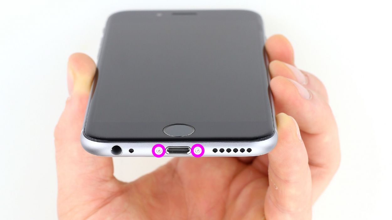
– To get your iPhone 6 open, grab a pentalobe screwdriver and let’s get to work!
– On the bottom side of your device, you’ll spot two Pentalobe screws, one on each side of the Lightning connector. Remove those little guys and toss them into a square on your magnetic pad. You’ve got 2 x 3.8 mm pentalobe screws to deal with!
Step 3


– Start by placing your iPhone 6 on a soft, clean surface to keep that back cover scratch-free.
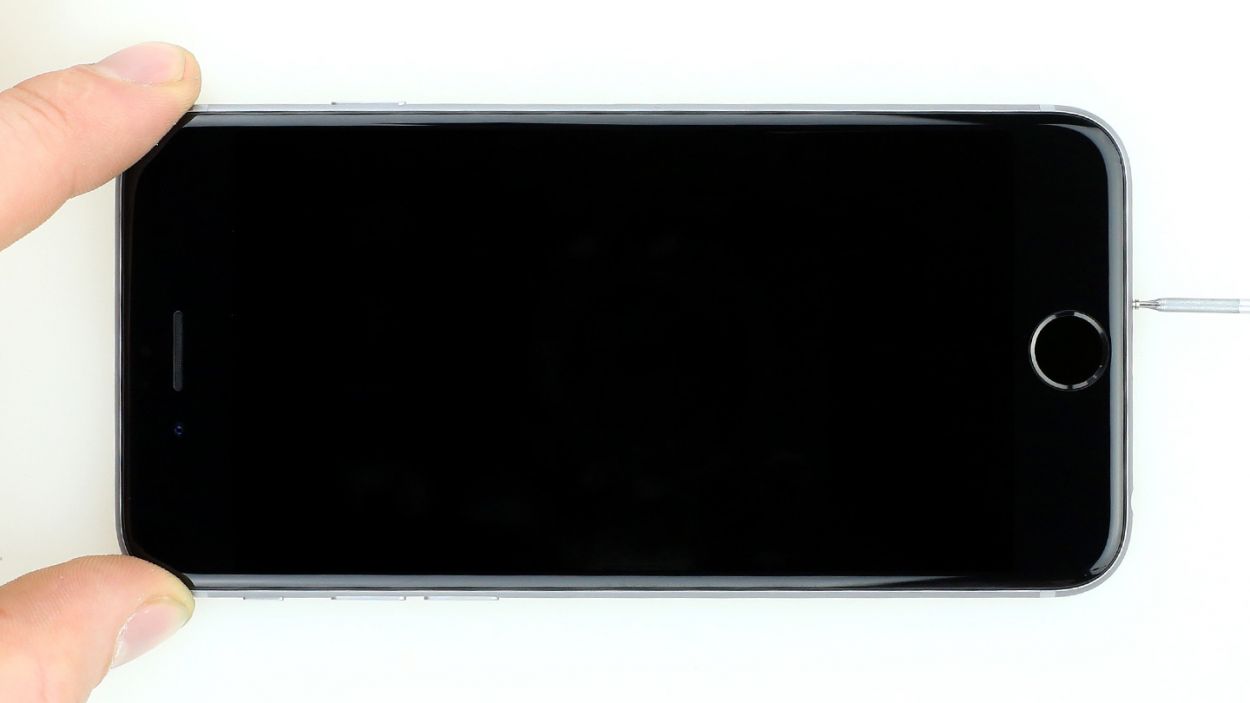
– Grab a suction cup and a hard plastic plectrum to gently lift the front screen. If your screen is looking a bit worse for wear, consider taping it up first to shield yourself from any pesky glass shards.
– Position the suction cup on the display, ideally right above the Home button, or just next to it (check out figure 1). Use the suction cup’s ring to lift the screen while you slide the plectrum between the aluminum and display frame, pushing the aluminum frame downwards. This will help you lift the screen with the plectrum (see figure 2). Remember, patience is key here—you might need a few tries!
– Once you’ve managed to lift the display a bit, carefully work your way around the edges until both long sides are free (see figure 3).
Step 4
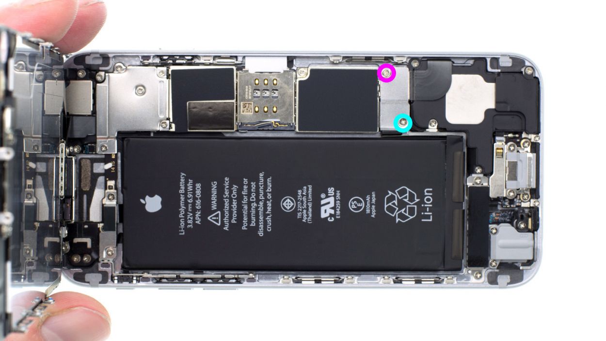


– Use a Phillips screwdriver to remove the Phillips screws that are attached to the battery connector (see figure 1). Take off the cover (see figure 2) and put all parts in the same container.1 x 3.2 mm Phillips screw1 x 2.3 mm Phillips screw
– Now carefully remove the battery connector. To do this, use the sharp end of the ESD spudger – go very gently under the plug (see figure 3). You do not have a spudger available? You can also try to remove the plug with your fingernail.
Step 5
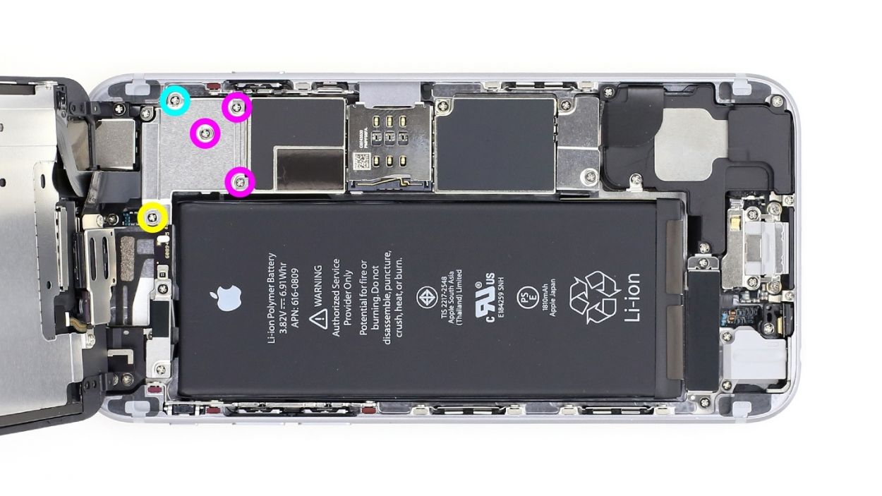

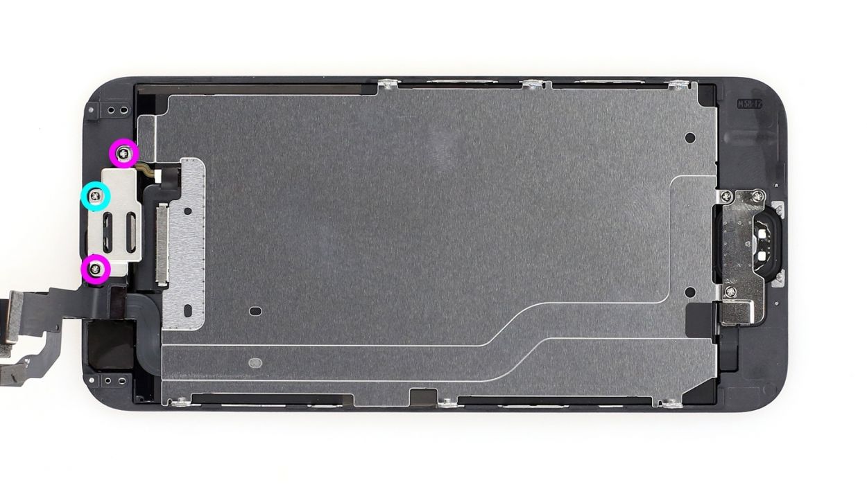
– The silver cover is fixed with five Phillips screws. Remove them (see figure 1) and place the screws in one section of the magnetic pad. Then you can remove the cover.1 x 3.1 mm Phillips screw3 x 1.3 mm Phillips screw1 x 1.8 mm Phillips screw
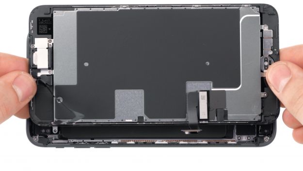
– Now you see four overlapping connectors (see picture 2). Loosen them very carefully in the order shown below. To do this, gently go under the contact with the pointed side of the spudger and lift it up.Front camera/sensor/earpiece/ambient microphoneTouch ID cableLCDTouchscreen
Step 6


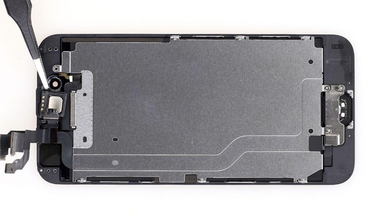
– The earpiece is cleverly tucked away on the back of the display unit. Grab your trusty Phillips screwdriver and let’s tackle those three screws holding the cover in place (see figure 1). Be sure to toss them into your screw container for safekeeping! You’ll be dealing with 2 x 2.2 mm Phillips screws and 1 x 3.0 mm Phillips screw.
– Next up, gently lift off the cover and add it to your screw container with the other little friends you removed earlier (check out figure 2 for guidance).
– Now, give the cable a little nudge to the side, just enough to wiggle that earpiece out (see figure 3). You got this!
Step 7
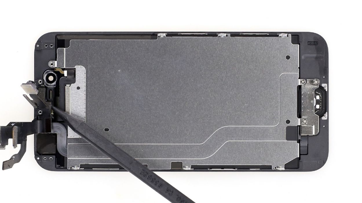


– Let’s tackle that cable set in two easy steps! First, grab your trusty spudger and slide it right below the cable set, just above the little gold ambient microphone. Give it a gentle lift to pop those sensors out (check out figure 1 for a visual!).
– Next, slide the spudger under the ribbon cable where the ambient microphone is hanging out (see figure 3). It’s got a bit of glue holding it down, so be gentle.
– Now, you can lift the cable set right out (see figure 3). You’re doing great!
Step 8
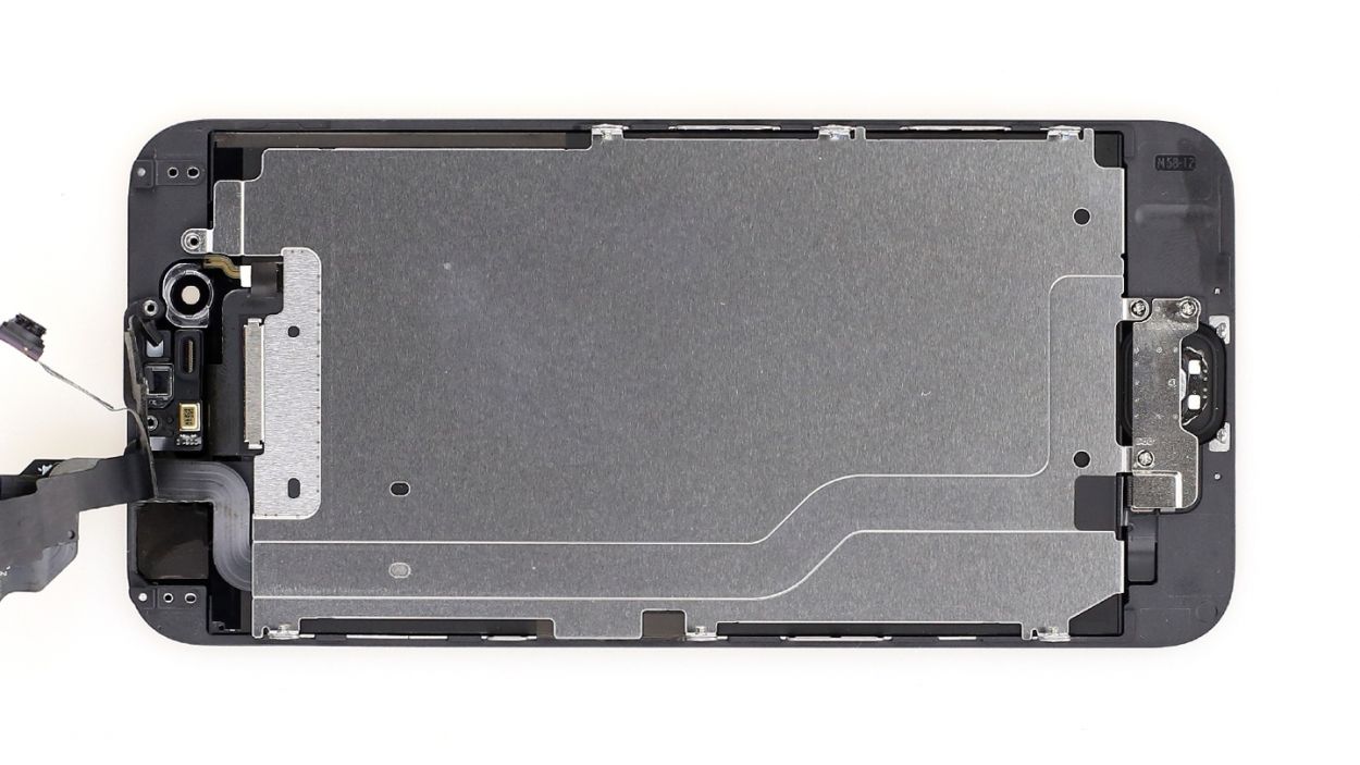

Getting those sensors in the right spot is key, or the proximity sensor will be playing peek-a-boo instead of working properly!
– First stick the ambient microphone to its original position (see figure 1).
– Then attach each of the sensors to the corresponding bracket (see figure 2).It’s important to position the sensors correctly because, otherwise, the proximity sensor won’t be fully functional.
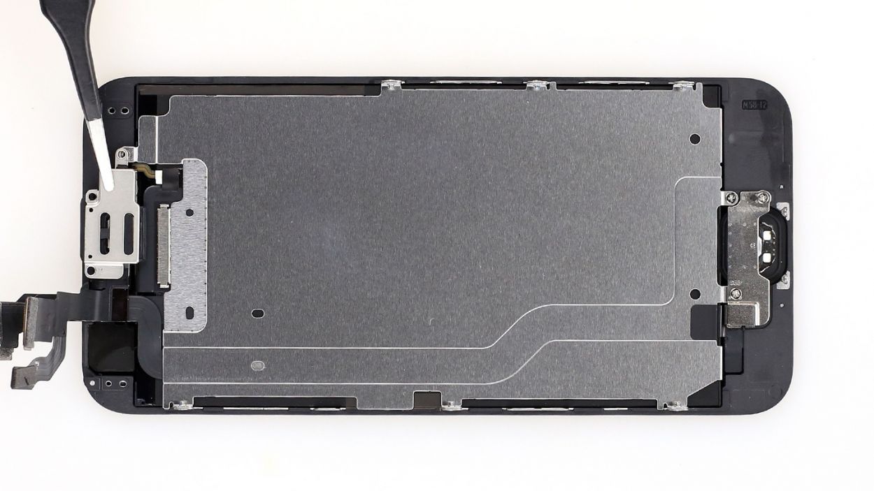
Step 9
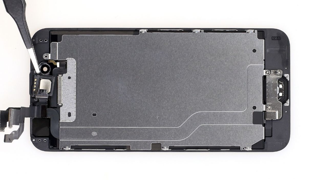
Remember, not all screws are created equal! If you mix them up, one of those little guys could press against your display glass from the inside and cause some unwanted damage.
– Put the earpiece back in its original position between the FaceTime camera and the sensors (see figure 1). Then put the cover back on (see figure 2).
– Now fasten the Phillips screws (see figure 3). Make sure the front camera is centered on the front of the display. Move it slightly if necessary.2 x 2.2 mm Phillips screw1 x 3.0 mm Phillips screw
Step 10

If you see streaks on the display or the touchscreen is partially not working, the connectors are not connected properly.
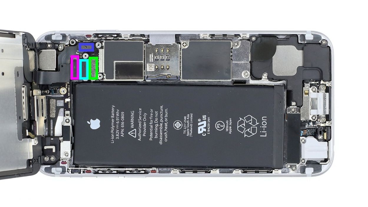
– Alright, champ, let’s connect that LCD connector (see figure 1)! It might take a couple of tries—no sweat if it doesn’t click in right away. Just be super gentle so you don’t bend the plug. We’re talking about the Front camera/sensor/earpiece/ambient microphone, Touch ID cable, LCD, and Touchscreen connectors here.
– Once those connectors are snug as a bug in a rug, fire up your iPhone 6! Let’s do some quick tests to make sure the LCD, touchscreen, proximity sensor, front camera, and earpiece are all singing and dancing. If you spot any weird streaks on the screen or the touchscreen is acting a little funky, double-check those connectors.
– Time to put the cover back on those connectors and secure it with those five screws (see figure 2): 1 x 3.1 mm Phillips screw, 3 x 1.3 mm Phillips screws, and 1 x 1.8 mm Phillips screw. You’re a rockstar!
Step 11


– It’s time to reconnect that battery! Let’s bring it back to life.
– Next up, slide that shiny silver cover back into the case and secure it with the screws: 1 x 3.2 mm Phillips screw and 1 x 2.3 mm Phillips screw. You’ve got this!
Step 12
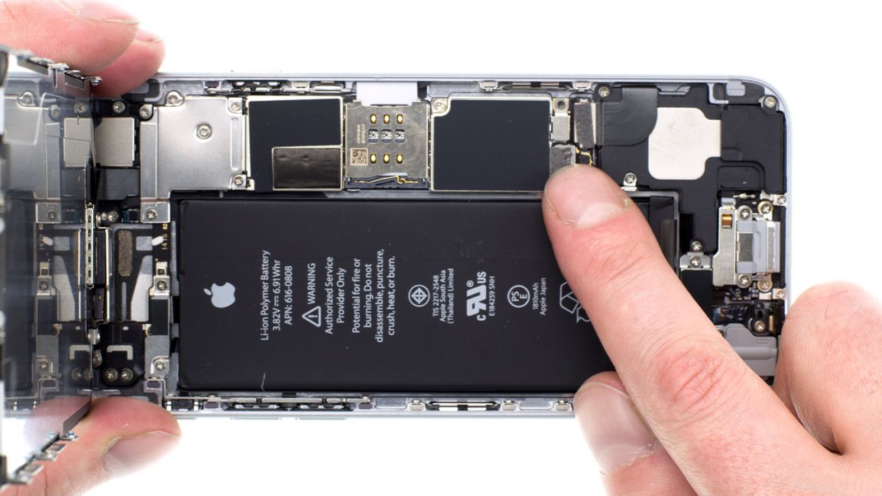
– You’re nearly there! Carefully put the display back into the housing. Be careful not to pinch any cables and make sure that the edge at the top of the screen really clicks into place.
– Now carefully push your screen on towards the home button so that it fits correctly in the frame.
Step 13

– Gather those final Pentalobe screws and give them a warm welcome as you insert them into the lower side of your device’s body. You’ve got 2 x 3.8 mm pentalobe screws ready to shine!