How to Replace Mac Pro Processors 2006-2008 Guide
Duration: 45 minutes
Steps: 46 Steps
Hey there! Get ready to dive into the world of processor replacement—it’s a bit of a challenging adventure, but totally worth it! Once you’re done, you’ll be cruising on a zippier computer and rocking a deeper knowledge of your Mac Pro. Let’s do this!
Step 1


Heads up! Always power down your device before diving in to prevent any mishaps with its internal parts or the new components you’re about to add. Keep it cool and don’t try to tinker while it’s still buzzing with energy.
Just a friendly reminder: After you shut down your system, those internal parts can still be a bit toasty! Give your device some time to chill before you get back to work.
– Power down the computer, friend.
– Give it a rest for 5 to 10 minutes to cool its circuits.
– Unplug all the external cables, but keep the power cord connected for now.
– Touch the metal PCI access covers on the back to discharge any static in your body.
– Now you can unplug the power cord.
– Slip on an ESD wrist strap to keep everything safe.
Step 2

Caution: The edges of the access panel and enclosure can be a bit sharp. Handle them with care to keep your fingers safe and sound!
Remember to keep the latch up before popping the access panel back on. If it’s down, the panel won’t sit right in the case. If you need help, you can always schedule a repair.
– 1) Grip the side access panel and lift the latch on the back of the computer.
– 2) Take off the access panel and lay it on a soft, clean cloth on a flat surface.
Step 3

To get rolling, make sure your hard drives check off these must-have specs:
– Type: Choose between the cool Serial Attached SCSI (SAS) or the smooth Serial ATA (SATA) 3 Gb/s.
– Width: It’s a sleek 3.9 inches (102 mm) wide, perfect for fitting in those tight spaces!
– Depth: Going deep? It’s just 5.7 inches (147 mm) deep, so you won’t have to worry about it sticking out too much.
– Height: Standing tall at 1.0 inch, it’s compact and ready to roll!
Step 4

Heads up! When you’re installing SAS drives in that snazzy Mac Pro (Early 2008), don’t forget to pop in the optional Mac Pro RAID Card too. You’ve got this!
Step 5

Heads up! Make sure that the latch on the back panel is in the up position. If it’s down, the hard drives and carriers are securely locked in, and you won’t be able to get them out. Keep it up for a smooth removal!
– Before you start, get your computer ready by opening it up and placing it on its side with the access panel facing upwards. If you need help, you can always schedule a repair
Step 6

– First up, give that back panel latch a little lift to unlock those drives and carriers. We’re getting ready to roll!
– Now, carefully slide that hard drive right out of the drive bay. You’ve got this!
Step 7

Heads up! When grabbing the drive, hold it by the edges. Avoid poking the printed circuit board at the bottom – it likes its personal space!
Quick Tip: Gently glide the carrier and drive along the guides, easing it into the drive bay. Give it a little push until you hear that satisfying snap. It’s right where it needs to be!
– Ready to swap out that hard drive? Start by taking out the four screws that hold the old drive to the carrier, then pop in the new drive and secure it in the carrier like a pro!
Step 8


– Ready to take out that standard card or one with a booster cable? First things first, you’ll need to loosen up those two captive screws holding the PCI bracket to the enclosure. Once you’ve done that, remove the bracket and you’re good to go!
Step 9

When handling the card, be sure to grip it by the edges only. Keep your fingers away from the connectors and components to avoid any mishaps. To remove the card, lift it straight up from the connector. For reinstallation, simply insert it straight back into the connector. Avoid rocking it side to side or forcing it into the slot. Once the new card is in place, give it a gentle tug to ensure it’s secure.
– 1) Give that tiny locking clip at the front of your card’s logic board connector a gentle nudge upwards toward the media shelf to set it free.
– 2) Grasp the card by its top corners and gracefully lift it up, sliding it right out of its cozy expansion slot.
Step 10


Some graphics cards might need either one or two booster cables to connect to the auxiliary power connectors on the logic board. No sweat!
For instance, the NVIDIA GeForce 8800 GT gets by with just one booster cable, while the NVIDIA Quadro FX 5600 likes to keep it cozy with two booster cables. Got it?
If you’re swapping out an old booster cable for a shiny new one, simply disconnect it from the card first. Easy peasy!
– Unplug the booster cable(s) from the logic board.
– Pop open the small locking clip at the front of the card’s logic board connector by nudging it up toward the media shelf.
– Grip the card by the top corners, lift it gently, and slide it out of its expansion slot.
Step 11

Replacement Tip for One Booster Cable: Make sure to plug that booster cable into the right auxiliary power connector on the logic board. For a card in PCI slot 1, connect it to the lower connector. For a card in PCI slot 2, you’ll want to go with the upper connector.
Replacement Tip for Two Booster Cables: Simply connect both cables to the two auxiliary power connectors. Easy peasy!
Step 12

Heads up: When using all four PCI Express slots, keep an eye on the total power consumption – it should be 300 W or less. If you need help, you can always schedule a repair
Removing graphic cards is a breeze! Just remember that while the process is pretty much the same for all PCI Express Cards, there might be a few small differences in the cards themselves. You’ve got this!
Step 13


Hey there! The heatsink cover is secured with some sneaky tabs and magnets underneath. Make sure you pop those tabs loose before attempting to remove the cover from the enclosure. If you need help, you can always schedule a repair.
– Quick check: all PCI Express cards safely out and stowed away?
– Put your fingers under the lip of the heatsink cover closest to the logic board. Lift the lip slightly toward the media shelf to pop the tabs and magnets under the top face of the cover.
– Keeping your fingers under the cover’s bottom lip, lift it straight up to release the remaining tabs and magnets under the front face.
– Slide the cover off and you’re good to go!
Step 14

Replacement Note: As you get ready to pop that processor heatsink cover back on, remember to line up those little tabs on the underside with the slots right below. (Those slots are hanging out on the front fan and memory cage, flanking either side of your heatsink cover.)
Step 15

– Hey there! Before you dive into removing the Front Fan Assembly, don’t forget to take out the first two bays of the hard drives and all PCI express cards. Make sure to stash them away safely, alright?
– Now, grab your trusty long-handled, magnetized #1 Phillips screwdriver. It’s time to remove that sneaky screw located at the top rear of the front fan assembly, which keeps it snugly attached to the logic board.
Step 16

– Now it’s time to remove the second Phillips screw located at the bottom front of the assembly. Take your time and make sure it’s out completely. If you need help, you can always schedule a repair
Step 17

– Grab the fan with one hand at each end, then give it a gentle lift straight up to smoothly detach it from the enclosure. You’ve got this!
Step 18


Quick Tip: Before you pop that front fan assembly back into the enclosure, double-check that those fan cables are cruising through the fan channel just right.
Quick Tip: Make sure all those AirPort and Bluetooth antenna wires are out of the way before you gently lower the fan assembly onto the logic board.
Step 19

– Quick tip: Don’t forget to make sure the latch located on the inside top left edge of the fan assembly clicks into place with the slot on the inside lip of the enclosure. It’s like giving it a little hug – they need to be close for everything to run smoothly!
Step 20

To upgrade your Mac Pro (Early 2008), you’ll need DIMMs that fit these specs:
Hey there! You can install extra pairs of 1 GB, 2 GB, or 4 GB FB-DIMMs in those open DIMM slots to give your device a memory boost. Just keep in mind, the maximum you can go is 32 GB!
When installing DIMMs, make sure they come in pairs of the same size and type from the same vendor. Check out the handy illustration provided—it’s like matching outfits for your computer!
Quick note: For your Mac Pro (Early 2008) to run smoothly, Apple suggests sticking to Apple-approved Mac Pro (Early 2008) FB-DIMMs. Your device will thank you!
– Get ready for some serious RAM power – we’re talking 800 MHz, DDR2, FB-DIMMS here!
– Now, let’s talk specs: these modules are 72-bit wide, 240-pin, and can handle up to 36 memory ICs per DIMM – that’s some serious memory muscle!
– And don’t worry about errors, these DIMMs have got error-correcting code (ECC) to keep things running smoothly. If you need help, you can always schedule a repair
Step 21

Heads up! It’s a smart move to let your computer chill for about 5–10 minutes before you dive in to remove or install memory. Those DIMMs can get pretty toasty!
Step 22

– Grab the memory riser card by those handy two finger holes, gently wiggle it out of the memory cage, and then lay it down DIMM side up on a soft, clean cloth. You got this!
Step 23

– Gently push the ejectors on the DIMM slot outwards, and then carefully lift the DIMM off the riser card. You’ve got this!
Step 24

Heads up! FB-DIMMs come with heatsinks on both sides. It’s best to leave those heatsinks alone, as trying to remove them could lead to some serious DIMM damage. Stay safe and keep those heatsinks where they belong! If you need help, you can always schedule a repair.
Replacement Reminder: Make sure to line up the DIMM with the slot on the riser card, then give it a little push on both ends until you hear those ejectors click back into action. You’ve got this!


Step 26

– With a magnetized #1 Phillips screwdriver (long-handled for that extra reach), loosen the four captive screws holding the memory cage to the logic board. Feel the satisfaction!
– Rotate the computer to a vertical position. Using a short-handled or right-angled jeweler’s #1 Phillips screwdriver (magnetized for precision), carefully remove the two short screws securing the memory cage to the bottom panel of the enclosure. Steady hands, you’re almost there!
Step 27

– Hey there, use your pointer finger to slide under the fan and gently pop the latch closest to the logic board. If you need help, you can always schedule a repair.
Step 28

– Grab your trusty flat-blade screwdriver and give those two latches near the front of the computer a gentle nudge to release them. You’re doing great!
Step 29

– Now it’s time to get the rear fan into its new home – gently slide it into the memory cage.

Step 31

Replacement Note: When installing a new fan in the memory cage assembly, give it a little spin into the cage, just like the illustration shows. Take a close look at how the fan lines up with the cage, too. If you need help, you can always schedule a repair
Step 32


Before popping in the memory cage and fan, make sure all logic board cables below the cage are out of the way. This will ensure the cage sits nicely and the cables don’t get pinched or damaged when you tighten those screws.
To install the memory cage and fan, maneuver the cage into position in the enclosure. Tighten at least two of the captive mounting screws. Then, slide the fan toward the back panel until you hear it snap into place. If you need help, you can always schedule a repair.
– Before installing the cage in the enclosure, make sure to insert the fan partway into the cage – it’s a crucial step to get right. If you need help, you can always schedule a repair
Step 33

This guide covers the 2.8 GHz and 3.0 GHz Mac Pro (Early 2008) setups. If you’re rocking the 3.2 GHz version, check out the notes that mention ‘Processors, 3.2 GHz.’ If you need help, you can always schedule a repair
Step 34

Let’s dive in and get that processor out! Here’s how to remove the lower processor (CPU B). Don’t worry, the same steps apply for removing the upper processor (CPU A). If you need help, you can always schedule a repair.
– Whenever you take out a processor, it’s super important to slather on some fresh thermal grease on that processor heatsink. Don’t worry, we’ve got you covered! New grease and handy alcohol wipes to clean off the old stuff are included with your replacement processors. Plus, you’ll find all the tips for applying the grease right there in the processor heatsinks procedure. If you need help, you can always schedule a repair.
Step 35


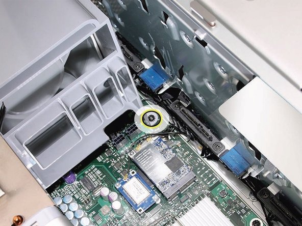
– Time to give that upper processor (CPU A) heatsink a little breathing room! Go ahead and unplug the 2-pin cable from the logic board. You’ve got this!
Step 36

– Grab your trusty long-handled, magnetized 3 mm flathead hex screwdriver and loosen those four captive screws securing the upper processor heatsink, following the order shown below. It’s like a mini treasure hunt!
– Now, gently lift the heatsink straight up and out of the enclosure. You got this!
Tools Used
- screwdriver%20Desktops%20repair+Repair&linkCode=ll2&tag=salvationrepa-20&linkId=1c0aa533b7b8148cb48741a4635ea648&language=en_US&ref_=as_li_ss_tl” rel=”nofollow noopener”>Long-handled, magnetized 3 mm flathead hex screwdriver
Step 37

– It’s time to give that lower processor (CPU B) heatsink a little break! Gently disconnect the cable connector and let it chill for a moment.
Step 38


– Grab your trusty long-handled, magnetized 3 mm flathead hex screwdriver and gently loosen those four captive mounting screws for the lower processor heatsink in the order shown below. You’ve got this!
– Now, with a bit of care, tilt that heatsink just right so it clears the bottom lip of the enclosure, and then lift it out of the computer like a pro. Easy peasy!
Tools Used
- screwdriver%20Desktops%20repair+Repair&linkCode=ll2&tag=salvationrepa-20&linkId=1c0aa533b7b8148cb48741a4635ea648&language=en_US&ref_=as_li_ss_tl” rel=”nofollow noopener”>Long-handled, magnetized 3 mm flathead hex screwdriver
Step 39

Heads up! Don’t slather on more grease than necessary. Keep it neat – no overflowing onto the processor connector.
Once you’ve successfully installed the new processors, it’s time to get those heatsinks back in place. Let’s dive into the next steps and keep the good vibes rolling!
– Let’s get that existing heatsink ready for a second round! If you happen to have a shiny new heatsink, jump over to the NEW Heatsink process.
– Grab the alcohol pad that came with your logic board or processor replacement kit and give the processor and the bottom of the heatsink a good scrub to remove any leftover thermal grease. Your heatsink will thank you!
– Now it’s time to add some fresh thermal grease! Use the one included in your replacement kit and put a little dot on the raised square area on the bottom of the heatsink.
– Spread that grease out evenly across the square, aiming for about 1 mm thick. Make that surface nice and smooth—your processor deserves it!
Step 40


Alright, once you’ve got those shiny new processors in place, it’s time to get those heatsinks back on! Let’s do this.
Heads up! No need to slather on thermal grease for your new heatsink. It’s already got some good stuff pre-applied, just waiting under a little cap. Make sure to pop that cap off before you install it!
– Getting Your New Heatsink Ready for Installation! If you’ve got an existing heatsink, just follow the steps for the EXISTING Heatsink.
– Grab that top gasket from the parts box and place it right on top of the heatsink.
– Replacing the lower processor heatsink? Don’t forget to pop on the bumper from the parts box onto the side of your new heatsink.
Step 41

The Mac Pro (Early 2008 Dual 3.2 GHz) computer is equipped with a unique coating on its processor heatsink and processor to keep things cool and collected. This shiny silver coating is thoughtfully applied to the underside of the heatsink and the top of the processor, ensuring optimal temperature management while you work your magic! If you need help, you can always schedule a repair.
– Alright, follow these simple rules when handling the processor heatsink and/or processor:
– 1. Slip on those disposable nitrile or latex gloves.
– 2. Steer clear of touching the shiny silver-colored coating on the underside of the heatsink and the top of the processor. Keep those fingerprints off!
– 3. Give a quick visual once-over of any heatsinks and processors before popping them into the computer.
– 4. If you’re removing or swapping out the heatsink and/or processor, keep the heatsink and processor together as much as possible. No more than a 30-minute separation, as the special coating degrades with exposure to air. Extended exposure could spell trouble for your computer and lead to a repeat repair job.
– If you need help, you can always schedule a repair
Step 42

Before you pop in a new or existing heatsink, make sure the gasket around the shiny coating on the underside is in tip-top shape, as shown in the graphic. If you spot any damage like cracks, folds, or broken surfaces, or if it’s out of place, swap it out!
You can find the gasket through GSX as part of the Mac Pro Grease Kit, part number 076-1258. If you need help, you can always schedule a repair
Step 43

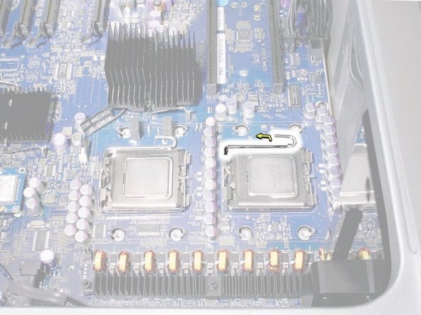
Grab a flat-blade screwdriver to gently pop those latches loose. You’ve got this!
– Pop open the latch on the metal processor holder.
Step 44


Hey there! When you’re taking out or putting in a processor, make sure to grab it by the edges like a pro. Be super cautious not to touch those shiny gold pins on the bottom – they’re like divas that can’t stand a little contamination! And don’t forget to keep your fingers away from the gold pins in the processor socket on the logic board. If you need help, you can always schedule a repair.
To figure out your processor’s speed, check out the etching on it! Just remember to wipe off any thermal grease first—it’s like giving it a little spa treatment to reveal its true potential.
– Swing the top of the holder open like a welcoming door!
– Gently lift the processor out of its cozy holder.
Step 45

Heads up! Before popping in your new processor, be sure to take off the protective cap from its connector. If you need help, you can always schedule a repair.
Step 46

Install Note: When popping in the processor on the logic board, line up the processor’s notch with the tab on the processor holder. Then, gently drop the processor straight into the socket.
FYI: Unlike older Power Mac G5 models, swapping out a processor in a Mac Pro (Early 2008) doesn’t require running the Apple Service Diagnostic for thermal calibration. If you need help, you can always schedule a repair.