How to Replace MacBook Pro 13 Unibody Early 2011 Logic Board
Duration: 45 minutes
Steps: 28 Steps
Hey there! Just a friendly reminder that you should take extra care while handling your device. If you run into any trouble, remember, you can always schedule a repair with us!
Get ready to dive in and swap out that logic board! Follow this guide for a step-by-step journey to a successful replacement. If you need help, you can always schedule a repair.
Step 1

– Unscrew and remove these ten little screws to get the party started!
Step 2


– Get those fingers ready and gently lift the lower case away from the MacBook’s body near the vent—it’s like giving your laptop a little hug!
– Now, go ahead and completely remove the lower case. You’re doing great!
Step 3


For a smooth escape, gently pry up on both short sides of the connector to coax it out of its socket. Just a heads up, watch those corners—connectors can be a bit fragile and might break off if you’re not careful!
– Gently use the edge of a spudger to nudge the battery connector up and away from its cozy spot on the logic board. You’ve got this!
Tools Used

Step 4

– G
– o
–
– a
– h
– e
– a
– d
–
– a
– n
– d
–
– g
– e
– n
– t
– l
– y
–
– w
– i
– g
– g
– l
– e
–
– t
– h
– a
– t
–
– b
– a
– t
– t
– e
– r
– y
–
– c
– a
– b
– l
– e
–
– a
– w
– a
– y
–
– f
– r
– o
– m
–
– i
– t
– s
–
– l
– i
– t
– t
– l
– e
–
– b
– u
– d
– d
– y
–
– o
– n
–
– t
– h
– e
–
– l
– o
– g
– i
– c
–
– b
– o
– a
– r
– d
– ,
–
– s
– o
–
– i
– t
–
– d
– o
– e
– s
– n
– ‘
– t
–
– g
– o
–
– a
– l
– l
–
– ‘
– o
– h
–
– h
– e
– y
– ‘
–
– w
– i
– t
– h
–
– i
– t
–
– w
– h
– i
– l
– e
–
– y
– o
– u
– ‘
– r
– e
–
– w
– o
– r
– k
– i
– n
– g
–
– y
– o
– u
– r
–
– m
– a
– g
– i
– c
– !
Step 5


In the second and third pictures, you’ll spot the fan socket and connector. Just a friendly heads-up: be gentle while using your spudger to lift the fan connector straight up and out of its socket—don’t want to accidentally snap that plastic fan socket off the logic board! The layout of the logic board in the second picture might look a tad different from your device, but rest assured, the fan socket is still the same.
– Gently use the edge of a spudger to lift the fan connector up and out of its cozy little socket on the logic board. You’ve got this!
Step 6

– Unscrew the three little screws that are holding the fan snugly to the logic board. You’ve got this!
Step 7

– Gently lift the fan out of its cozy spot on the logic board, but watch out for its cable – it might try to tag along!
Step 8


– Grab that trusty spudger and gently coax the right speaker/subwoofer cable out from beneath the retaining finger snugly molded into the upper case.
– Now, give that right speaker/subwoofer cable a little lift to free the connector from its cozy home on the logic board.
Tools Used

Step 10


Grab your trusty spudger and gently pry those pesky cable connectors up from their cozy spots on the logic board. You’ve got this!
– Time to unplug those four cables!
Tools Used
Step 11


Just a friendly reminder: make sure you’re lifting up on the hinged retaining flap and not the socket itself!
– Gently lift the retaining flap on the keyboard ribbon cable ZIF socket using your trusty fingernail.
– Grab your spudger and carefully pull the keyboard ribbon cable out of its cozy socket.
– If the cable is being a bit stubborn, no worries! Just attach a little piece of tape to it, and it’ll help guide the cable back into the socket with ease.
Tools Used

Step 13


Just a friendly reminder: make sure you’re prying up on the hinged retaining flap, not the socket itself!
– Grab your trusty spudger or just your fingernail and gently lift the retaining flap on the keyboard backlight ribbon cable ZIF socket. You’re doing great!
– Now, carefully pull the keyboard backlight ribbon cable out of its cozy socket. You’ve got this!
Tools Used
Step 14

– Gently use the flat end of a spudger to lift the sleep sensor/battery indicator connector out of its cozy spot on the logic board. You’re doing great!
Tools Used
Step 15


Hey there! Just a heads up: be gentle with the display data cable. Its socket is a bit delicate, so instead of lifting it up, give it a nice, smooth pull parallel to the logic board. You’ve got this!
– Find that handy plastic pull tab attached to the display data cable lock and give it a little twist toward the DC-In side of your computer.
– Now, gently tug the display data cable straight out of its cozy socket on the logic board.
Step 16

In certain models, you might find that the screws are a tad shorter, just a heads up!
– Let’s get started by taking out those nine screws!
Step 17


– Time to get those screws out! Start by removing these two little guys:
– Next up, gently take out the display data cable retainer from the upper case. You’re doing great!

Step 19

– Carefully lift the logic board from the side closest to the optical drive, keeping an eye on those pesky connectors around the edges.
– Gently maneuver the board out of the upper case without bending it, and watch out for the flexible connection to the DC-In board that might try to hitch a ride in the upper case.
– And there you have it, the logic board is free!
Step 20

– Gently guide the microphone cable out of its cozy little home nestled in the left speaker enclosure.
Step 21

– Peel off the tiny black tape that’s covering the left speaker connector. You’ve got this!
Step 22

Gently lift from underneath the wires, and you’ll be on your way!
– Gently slide the flat end of your trusty spudger under the left speaker connector and lift it up from its cozy spot on the logic board.
Tools Used
Step 23

– Gently work your way around the left speaker, easing it away from the foam adhesive that’s keeping it cozy with the logic board.
– Now, give that left speaker a little wiggle and pull it out.
Step 24

– Peel away the black tape that’s hiding the microphone connector. It’s like unwrapping a surprise gift!
Step 25

– Gently tug the microphone cable upwards to free its connector from the logic board’s socket. You’ve got this!
– Now, go ahead and take out the microphone. Easy peasy!
Step 26

– Gently tug the MagSafe DC-In board cable towards the heat sink to free it from the logic board. You’re almost there!
– Carefully lift out the DC-In board. You’re doing great!
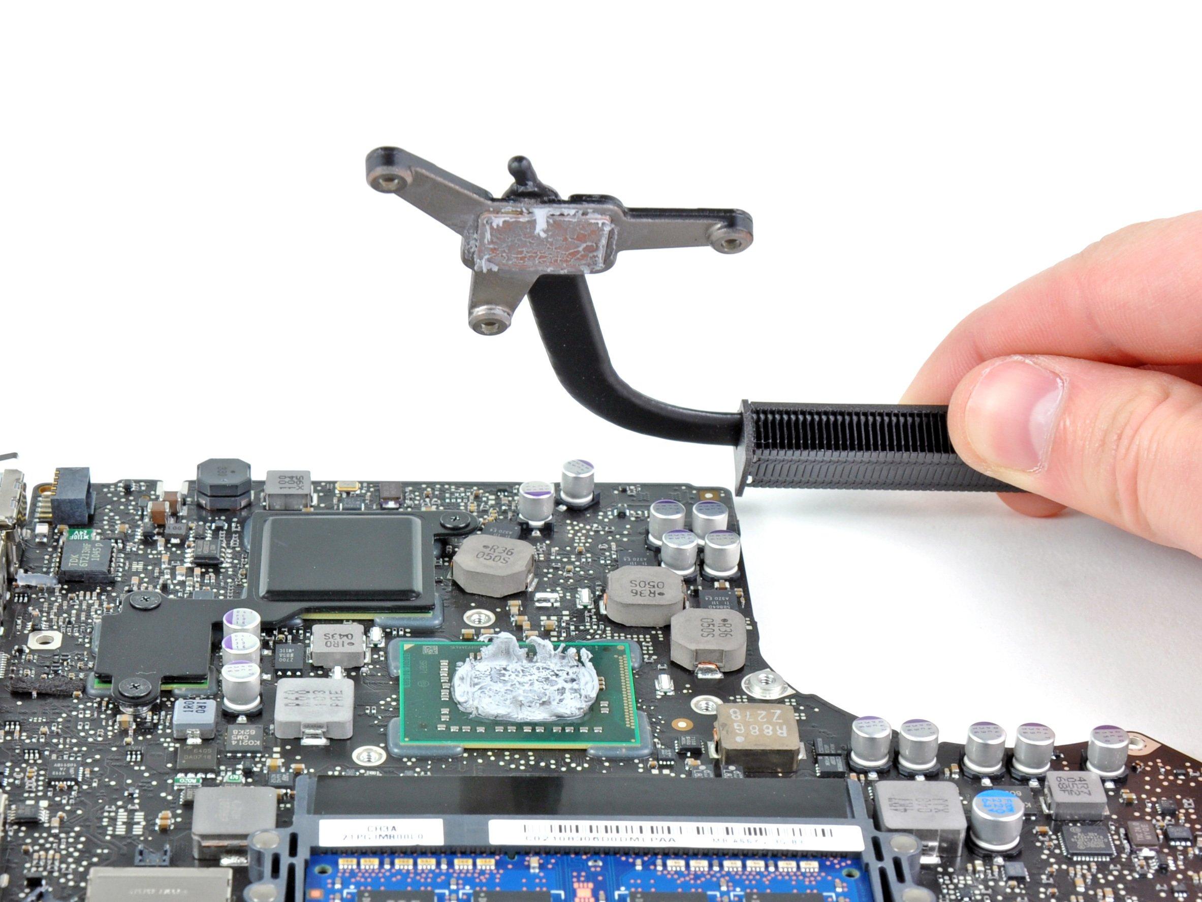
Step 27


Don’t forget to scrub off that old thermal paste and slather on a fresh layer before you pop the heat sink back on! We’ve got a handy guide to help you nail it.
If your heat sink is playing hard to get, don’t sweat it! A gentle nudge with a