How to Replace MacBook Pro 13 Unibody Logic Board Step-by-Step Guide
Duration: 45 minutes
Steps: 27 Steps
Heads up! Make sure to have a peek at the tutorial ‘friendly tutorial’. It’s super straightforward and easy to follow. Remember, this is your step-by-step guide to fixing things up! If you get stuck, don’t sweat it—help is just a click away at schedule a repair.
Follow this snazzy guide to swap out your logic board like a pro. Rock those tools and give your device a fresh start!
Step 1

– Unscrew the 10 screws that are keeping the lower case attached to the MacBook Pro 13″ Unibody.
Step 2

– Gently hoist the lower case a tad and nudge it to the back of the computer to unhitch those sneaky mounting tabs.
Step 3

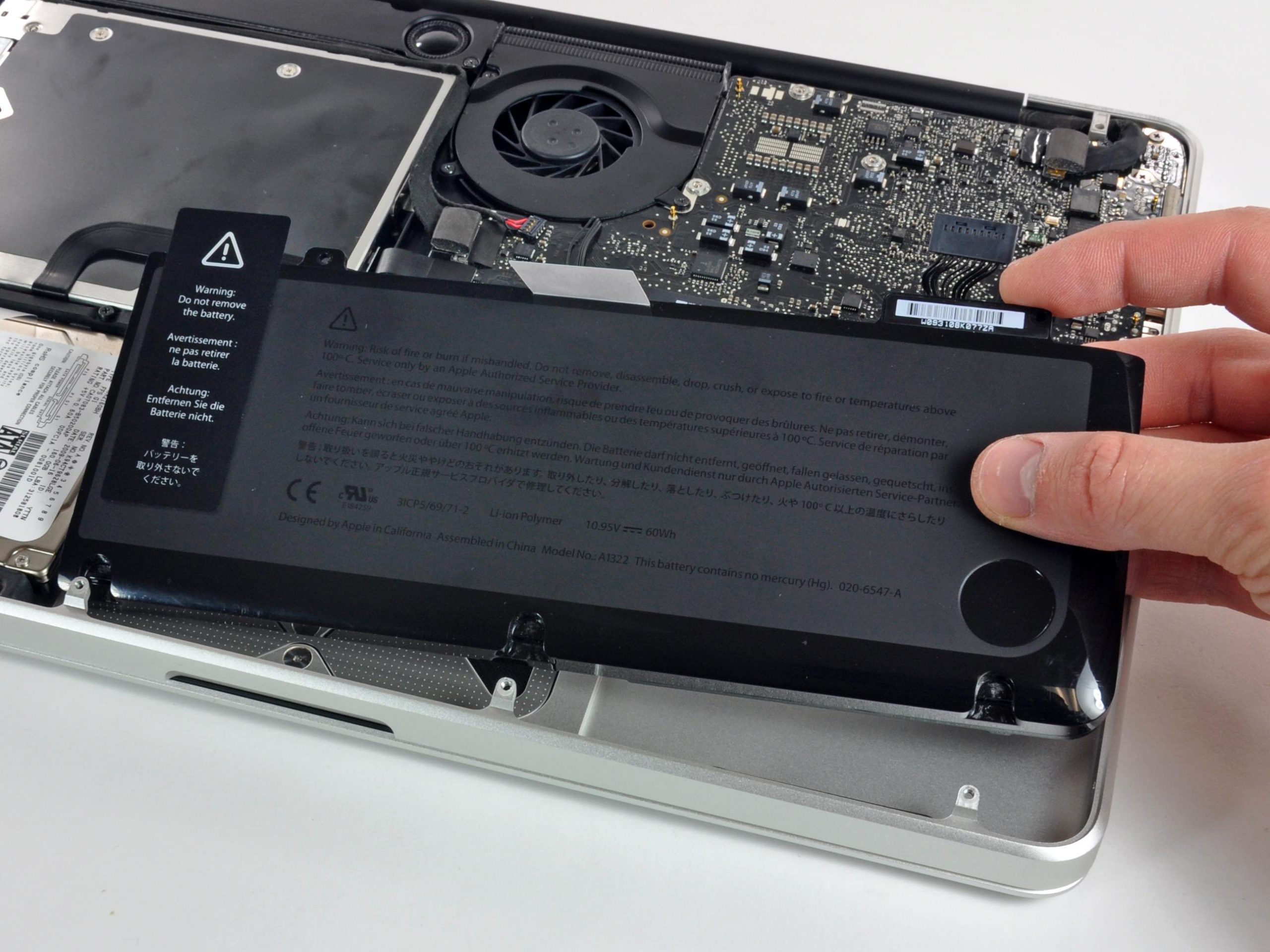
Just to be on the safe side, it’s a smart move to unplug the battery connector from the logic board to prevent any unexpected zaps.
– Grab your trusty spudger and gently pop the battery connector right out of its home on the logic board.
Tools Used

Step 4


– Grab your spudger and give the fan connector a gentle nudge out of its cozy home, then lift it right off the logic board like a champ!
Check out the fan socket and connector in the snaps! Just a heads up—be gentle when you’re leveraging that fan connector with your spudger. We wouldn’t want to snap that plastic fan socket off the logic board. While the layout might vary slightly from your gadget, the fan socket remains a constant. Keep it cool and carry on!
Tools Used


Step 9

– Grab the flat end of a spudger and give the subwoofer and right speaker connector a gentle nudge off the logic board. You’ve got this!
Tools Used
Step 10

– Slide the camera cable connector towards the optical drive like you’re scoring the winning goal. Disconnect it from the logic board with a celebratory snap!
Alright, camera cable detachment coming up! There’s typically a nifty little adhesive plastic retainer clinging to the logic board—kind of like a mini security guard for the connector. Make sure to gently move it aside before you disconnect the cable. Onwards!
Hey there, be careful with this metal socket—it’s a bit of a drama queen and bends easily. Just line up the connector with its cozy home on the logic board before you bring them together for a happy reunion!
Step 11


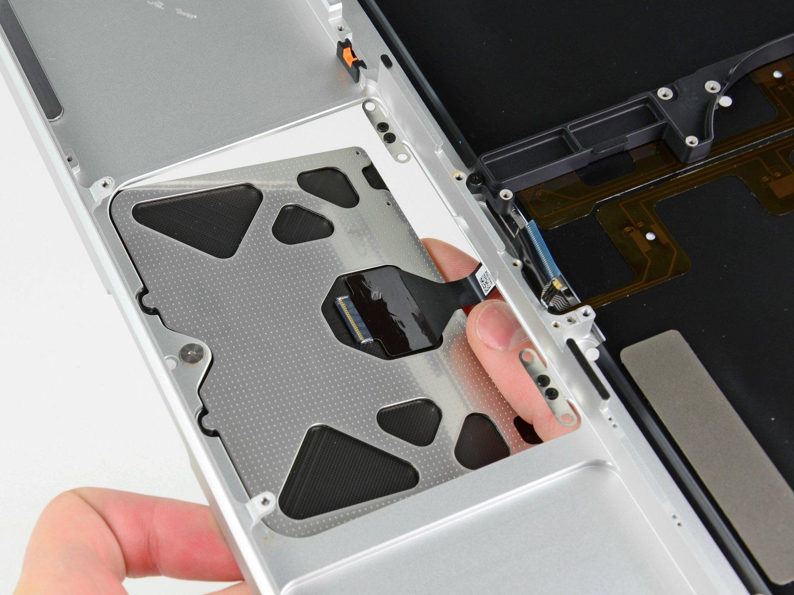
– Grab your trusty spudger and let’s pop those connectors! Gently lift the optical drive, hard drive, and trackpad connectors off the logic board with the flat end of your spudger. It’s like lifting mini pancakes off a tiny griddle!
Tools Used
Step 12


– Pop that cable flap open with your fingernail or a spudger like a pro to free the keyboard ribbon cable.
– Gently slide that keyboard ribbon cable out of its home with the help of your trusty spudger.
Tools Used
Step 13

– Gently remove the little strip of sassy black tape from the keyboard backlight ribbon cable socket. You got this!
Step 14


– Grab your spudger and gently flip up the cable retaining flap on the ZIF socket where the keyboard backlight ribbon cable lives.
– Now, nudge that keyboard backlight ribbon cable out of its socket with the spudger. Easy does it!
Tools Used
Step 15

– Grab the flat end of your spudger and gently pop the battery indicator cable connector off the logic board like a pro!
Tools Used

Step 17

– Time to unscrew some screws!


Step 19


Watch out! Make sure you don’t accidentally yank out the delicate connector of the microphone assembly—treat it like your favorite fragile gadget!
– Gently lift the logic board from its left edge, tilting it until the ports are free from the upper case’s embrace.
– Ease the logic board away from the upper case’s side and slide it out, being careful of the DC-in board that might snag.
Step 20

Each of these screws is sitting on a sneaky little spring, ready to jump away! Keep a sharp eye on them so they don’t bounce into oblivion.
– Unscrew the four 8.5 mm Phillips screws that are keeping the heat sink chillin’ on the logic board.
Step 21

When reattaching the heat sink to the logic board, remember to spread a fresh layer of thermal paste to keep things chill. Check out our easy-peasy guide to swapping out thermal paste and get your device cool as a cucumber in no time!
– Carefully elevate the heat sink away from the logic board with a flourish!
Step 22

– Remove the tape that’s chilling over the microphone cable connector and the left speaker cable connector. Let’s free these buddies up!
Step 23

– Grab your spudger and gently lift the left speaker connector off the logic board like a pro.
Tools Used
Step 24

– Grab your trusty spudger and gently lift the microphone cable connector off the logic board. It’s like coaxing a small chip into taking a little nap!
Tools Used
Step 25

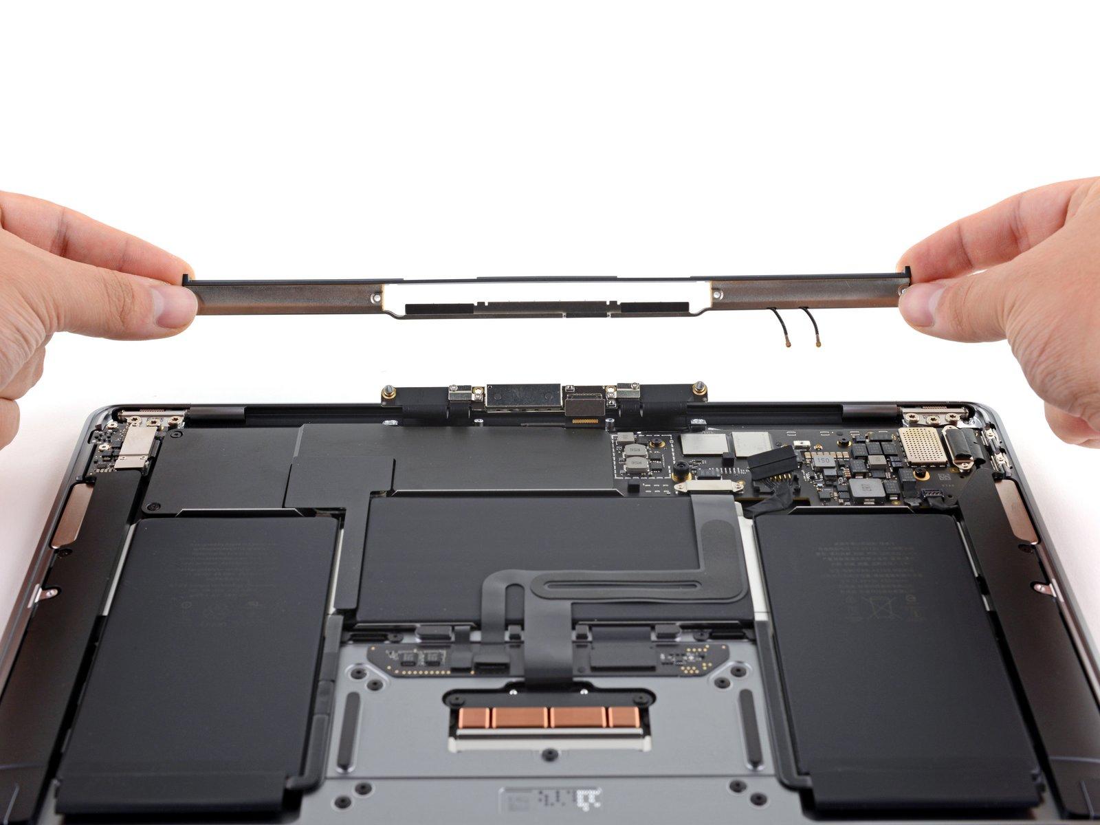
– Gently unstick the left speaker/microphone assembly from the gluey grips of the logic board with some smooth moves.
Step 26

– Unplug the DC-In board connector from its socket on the logic board like you’re unplugging a toaster after a successful toast. Easy-peasy!
Step 27


Give those tabs a gentle nudge and watch your chip spring into action like a jack-in-the-box! If there’s a buddy chip, go ahead and give it the same zippy treatment.
– Gently persuade the tabs on each side of the chip to let go by pushing them away from the RAM. Think of it as giving them a little nudge to do the right thing.
– Once the RAM chip springs into a slightly elevated position, gracefully slide it out of its socket.
– And there you have it! Just the logic board chilling by itself.