How to Replace MacBook Pro 14 Heat Sink – DIY Guide
Duration: 45 minutes
Steps: 64 Steps
Heads up! Make sure to keep track of your screws—they can be tricksters and might try to roll away. Keep them in a small container or a magnetic mat. Happy fixing!
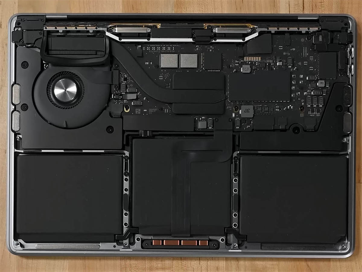
Ready to chill out your MacBook Pro 14″ like a pro? Dive into this guide to swap out the heat sink on your late 2023 model (rocking M3 Pro and M3 Max chips). Heads up, you’ll need to pluck out the whole logic board first, and don’t forget to snag some fresh thermal paste to seal the deal. A few snapshots might look a bit off since they’re from a cousin model, but no sweat, they’ll guide you just fine!
Step 1


– Power down your MacBook, snap it shut, and give it a flip. Keep that lid closed until you’ve said goodbye to the battery connection.
– Pull out the MagSafe and any gizmos plugged into your MacBook.
Step 2


Before diving in, ensure your MacBook Pro is fully powered off and unplugged. Close it up, flip it over, and let’s get this repair party started upside-down!
As you dive into this repair, make sure you keep a close eye on all those little screws! Pop them back exactly where they came from to keep your gadget happy and healthy.
– Grab your P5 Pentalobe driver and get ready to unscrew eight screws holding the lower case in place. Let’s make this happen!
Step 3


– Stick a suction cup near the front edge of the lower case, right between those pesky screw holes.
– Give that suction handle a hearty tug to pry open a small gap under the lower case.
Tools Used

Step 4


– Wedge your opening pick into that new crevice you just made.
– Whip the pick around the closest corner and cruise it up halfway along the side of your trusty MacBook Pro.
Step 5


– Now, let’s do that one more time on the flip side. Grab your opening pick and show that second clip who’s boss!
Step 6


The back edge of your MacBook features some sassy sliding clips that like to hold on tight to the lower case. You might need to flex some muscle to get them to let go—consider suiting up with gloves to guard your hands against the sharp attitude of the lower case edges.
– Gently tug on the lower case, working your way around one corner at a time to pop those sliding clips free. You’ve got this!
Step 7


– Pop off that lower case like a pro!
– When putting it back, just reverse the charm!
Step 8


– Slide off any sticky tape hanging out over the battery board data cable connector on the logic board. It’s like peeling a banana!


Step 10


– Slide out the battery board data cable from its socket on the logic board like you’re pulling a magic trick!
Step 11

Your MacBook might try to be exclusive with its Torx Plus screws, but guess what? Regular Torx bits will crash the party just fine! Just remember to keep the pressure steady and straight to avoid any screw-stripping drama.
– Grab your T3 Torx driver and whisk away those two tiny 2.1 mm-long 3IP Torx Plus screws that are holding the trackpad cable bracket to the logic board. It’s like a mini treasure hunt!


Step 13


To reconnect press connectors like our little friend here, line it up and give a gentle click on one side, then swing over to the other side and do the same. Avoid pushing in the middle like it’s a buzzer on a game show. If you miss align, you could bend those delicate pins, and that’s a one-way ticket to Bendsville, population: your connector.
– Grab the flat end of your trusty spudger and gently pop open the trackpad cable’s press connector from the logic board. It’s like unlocking a little tech treasure chest!
Tools Used


Step 15


– Slide off any sticky tape hanging out over the battery board data cable connector. Look for it under the big pancake screw.


Step 19

– Grab your T5 Torx driver and zap out that 3.8 mm 5IP Torx Plus wide-head screw holding down the battery power connector. It’s just one screw, you got this!
Step 20


Pop that connector up just enough to avoid any sneaky reconnections during your repair—aim for no more than a 45-degree angle to keep that hinge happy and healthy!
To boost your safety game, slip something like a playing card bit between the connector and board—it’s like a mini shield!
– Grab your trusty spudger and use the flat end to gently pry the battery connector off its board. It’s disconnecting time!
Tools Used
Step 21


– Grab your T3 Torx screwdriver and show those three 2.1 mm screws who’s boss! They’re just chilling there, holding down the antenna board bracket and the coaxial cable cover. Let’s get them out and move along with the repair party!
Tools Used

Step 22


– Grab your tweezers or just use your fingers to whip off the cover sitting on those snazzy antenna bar’s coaxial cables.
Step 23


– Grab your spudger and gently pry up to disconnect the antenna bar’s coaxial cable.
– Do the same for the other two cables.
– When putting it all back together, these connectors can be a bit fiddly. Just align each connector right above its socket and press down with the spudger’s flat end. You should hear a satisfying ‘click’ as it snaps into place.
Tools Used


Step 25


– Grab your tweezers or just use your fingers to whisk away those two pesky screen cable covers off the logic board.
Step 26


– Grab your trusty spudger and gently pop off the screen cable connectors on the right side of the logic board like a pro. It’s disconnecting time!
Tools Used
Step 27


Avoid prying near the fancy surface-mounted buddies next to the press connector—they’re delicate!
– Let’s do that magic trick again! Disconnect the next press connector located at the top left of the logic board. You’re a natural at this!
Step 28


– Slide that tape off the microphone cable connector like a cool magic trick!


Step 31


– Grab your T3 Torx driver and unscrew those nine 2.1 mm screws that are holding the right cable covers in place. Let’s get this party started!
Step 32


– Grab your tweezers or just use your fingers to whisk away those five cheeky right cable covers.
Step 33


– Gently peel away any tape that’s keeping the right speaker cable undercover.


Step 35


– Gently slide the right speaker cable out of its socket on the logic board, like you’re pulling a magic trick!
Step 36


– Grab your spudger and gently pop off the headphone jack’s press connector like a pro.
Tools Used
Step 37


– Grab your spudger and gently pop those right USB-C ports’ press connectors free like a boss.
Tools Used


Step 40


– Grab your T3 Torx driver and show those four screws on the left cable covers who’s boss. Unscrew them from the frame and let the fun begin!
Step 41


– Grab your tweezers or just use your fingers to whisk away those two sneaky left cable covers.
Step 42


– Gently lift and peel back any tape that’s hiding the left speaker cable. Let’s free that cable like a superhero rescuing someone tied to the tracks!


Step 44


– Gently slide out the left speaker cable from its cozy home on the logic board. It’s just a little wiggle and a pull—super easy!
Step 45


– Grab your spudger and gently pop off the left USB-C port’s press connector like a pro.
Tools Used
Step 46


The Touch ID sensor cable loves to stick to the frame like peanut butter to bread! If that sticky adhesive doesn’t give up when you disconnect the press connector, grab an opening pick and gently slide it under the cable to show it who’s boss.
– Grab a spudger and gently pop off the Touch ID sensor’s press connector located near the top left corner of your gadget.
Tools Used
Step 47


– Gently peel away any tape that’s hiding the connectors for the keyboard and its snazzy backlight. It’s like uncovering hidden treasure!
Step 48


– Grab a spudger and gently pop up the locking flap on the ZIF connectors for those keyboard cables. It’s like lifting a tiny treasure chest lid!
Tools Used
Step 49


– Unhook those zippy keyboard and backlight cables by gently sliding them out of their snug homes on the logic board.


Step 52


– Slide out the right fan cable from its cozy socket on the logic board like you’re pulling a magic trick. Ta-da!
Step 53


The right fan cable is just a bit sticky to the logic board. No biggie!
– Grab your tweezers and gently coax the fan cable off the logic board to free it from the sticky adhesive. It’s like detaching a band-aid – swift and satisfying!
Step 54


– Now, let’s give the left fan the same superstar treatment! Disconnect and reposition it just like we did with the first one.
Step 55


– Whip out your screwdriver and show those four black screw covers on the logic board who’s boss!
Step 56


– Grab your T5 Torx driver and get ready to unleash those 11 screws holding the logic board in place. Let’s unscrew with style!
Step 57


– Grab your T6 Torx driver and unscrew those three little rascals holding down the logic board!
Step 58


– Wedge a spudger into the right side between the logic board and the frame.
– Give that spudger a little upward nudge to pop the logic board free from its snug clips.
Tools Used
Step 59


– Wedge a spudger between the logic board’s bottom and the frame. It’s like lifting a treasure chest lid!
– Give that spudger a little pry-up action to pop the logic board free from its snug clips. Easy peasy!
Tools Used
Step 60


– Carefully hoist the logic board from its right side to pop it off those little pegs that keep it in place.
– Slide the logic board away from the device’s left side to free up the HDMI and SDXC ports from their cozy slots in the frame.
– Lift off the logic board and wave it goodbye!
Step 61


– When putting things back together, make sure to jazz it up with these steps:
Step 62


– Flip the logic board over so the heat sink screws are staring right at you!
– Grab your T5 Torx driver and whisk away the four 3.9 mm screws that keep the heat sink attached to the logic board. It’s like unscrewing the lid off a cookie jar!
– When putting it all back together, start by getting those screws just snug enough. Align the brackets and heat sink with a little wiggle, then secure them tightly in a crisscross pattern. It’s like doing the final twist on a dance move!


Step 64


– Use your fingers to gently lift the logic board away from the heat sink—like you’re lifting a slice of your favorite pizza!
– Carefully remove the heat sink.
– You’ll notice a thick, grey thermal compound that acts as a bridge between the logic board and the heat sink. If you’re removing the heat sink, it’s time for a thermal paste refresh! Check out our thermal paste guide to clear off the old stuff and apply a new, shiny layer.