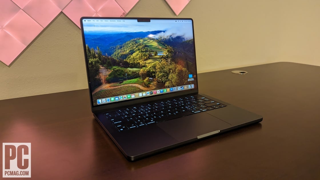
How to Replace MacBook Pro 14″ Late 2023 Fans
Duration: 45 minutes
Steps: 65 Steps
Heads up, tech adventurer! Make sure to handle your device with care during this fix. If things get tricky, don’t hesitate to hit up Salvation Repair for some backup!
Ready to give your MacBook Pro 14″ from late 2023 a little TLC? This guide will show you how to replace the fans, whether it’s just one or both. Keep in mind, you’ll need to remove the logic board, which isn’t your everyday laptop fix. So, gear up for a bit of a challenge! Also, note that some of the images might be from a similar model – minor differences, but nothing that will throw you off track. If things get tricky, you can always schedule a repair.
Step 1


– Alright, let’s get this party started! Power down your MacBook, snap that lid shut, and flip it over like a pancake. Keep the lid cozy and closed until you’ve successfully disconnected the battery.
– Next up, yank out the MagSafe cable and any other gadgets hitching a ride on your MacBook.
Step 2


Before we jump into the fun, make sure your MacBook Pro is completely powered off and unplugged. Close the lid, flip it upside-down, and let’s get started!
As you dive into the repair, keep track of each screw’s summer home—make sure they all vacation back to their original spots to keep your gadget happy and healthy!
– Grab your P5 Pentalobe driver and unscrew the eight screws holding the lower case in place. Let’s get this party started!
Step 3


– Stick a suction cup near the front edge of the lower case, right between those screw holes.
– Give that suction handle a good tug upwards to pry open a small gap beneath the lower case.
Tools Used

Step 4


– Pop an opening pick into the space you just made.
– Whoosh that pick around the nearest corner and glide it halfway up the side of your MacBook Pro.
Step 5


– Now, let’s do that one more time on the flip side! Grab your opening pick and let’s pop open that second clip with style.
Step 6


The back edge of your MacBook has some sly clips that might require a good deal of muscle to separate. Consider donning some gloves—those edges can be a bit nippy on the fingers!
– Gently tug the lower case away from the back edge, one corner at a time, to pop free those sneaky sliding clips.
Step 7


– Pop off that lower case like a boss!
– Slapping that lower case back on? You got this!
Step 8


– Gently peel back any tape that’s shielding the battery board data cable connector on the logic board. It’s like unwrapping a present!


Step 10


– Slide out the battery board data cable from its socket on the logic board like a pro. It’s just a little wiggle and tug!
Step 11

While your MacBook might flirt with some fancy Torx Plus screws, your regular Torx bits will do the trick just fine. Just remember to keep the pressure steady and straight to avoid any screw-stripping mishaps!
– Grab your T3 Torx driver and unscrew the two 2.1 mm-long 3IP Torx Plus screws holding the trackpad cable bracket in place. It’s a small step towards tech freedom!


Step 13


– Grab the flat end of your spudger and gently pop open the trackpad cable’s press connector from the logic board. It’s like lifting a tiny treasure chest lid!
To snap these tricky press connectors back into their happy place, just line them up gently and give one side a little love tap until it makes a satisfying click. Then, show the other side some love and repeat. Remember, middle pressing is a no-go—it’s all about the edges! Misaligning these little troublemakers can lead to some sad, bent pins, so keep those connections straight to avoid a connector catastrophe.
Tools Used


Step 15


– Gently peel back any tape hiding the battery board data cable connector right under the big ol’ pancake screw.


Step 19

– Grab your T5 Torx driver and unscrew the 3.8 mm 5IP Torx Plus wide-head screw that’s holding down the battery power connector. It’s just one little screw, you got this!
Step 20


Hoist that connector just high enough so it won’t sneakily reconnect during your fix—aim for no more than 45 degrees. Let’s keep it chill and avoid a hinge tragedy!
For a bit of added fun and safety, slip a piece of a playing card between the connector and board—it’s like a little safety shield!
– Grab the flat end of your spudger and give the battery connector a gentle nudge away from its board to disconnect the battery. Easy does it!
Tools Used
Step 21


– Grab your T3 Torx screwdriver and show those three 2.1 mm screws who’s boss! Remove them to free up the antenna board bracket and the coaxial cable cover. Let’s get that frame looking neat!
Tools Used

Step 22


– Grab your tweezers or just use your fingers to wiggle out the cover sitting on those snazzy antenna bar’s coaxial cables.
Step 23


– Grab your trusty spudger and gently pry up to disconnect the antenna bar’s coaxial cable.
– Do the same for the remaining two cables.
– When putting it all back together, these connectors can be a bit fiddly. Just position each connector right above its socket and give it a gentle press with the flat end of your spudger. You’ll hear a satisfying snap when it slots into place.
Tools Used
Step 24


– Grab your T3 Torx driver and show those four 2.1 mm screws who’s boss by removing them from the screen cable covers. Let’s get to it!
Step 25


– Grab your tweezers or just use your fingers to whisk away those two pesky screen cable covers from the logic board. Easy peasy!
Step 26


– Grab the flat end of your spudger and gently pop off the right-most screen cable connectors chilling on the logic board. It’s like unplugging a tiny, electronic puzzle piece!
Tools Used
Step 27


Avoid prying near those snazzy surface-mounted components next to the press connector—let’s keep them happy!
– Alright, let’s do that disconnect dance one more time with the press connector at the top left of the logic board!
Step 28


– Gently peel away any tape that’s hiding the microphone cable connector like you’re uncovering a secret treasure. Shhh, it’s just between us!


Step 31


– Grab your T3 Torx driver and show those nine 2.1 mm screws who’s boss! Unscrew them to free the right cable covers from the frame.
Step 32


– Grab your tweezers or just use your fingers to playfully pluck away those five cheeky right cable covers.
Step 33


– Gently pull away any tape that’s keeping the right speaker cable undercover.


Step 36


– Grab your spudger and give that headphone jack’s press connector a gentle pop to disconnect it.
Tools Used
Step 37


– Grab your spudger and gently pop off the right USB-C ports’ press connectors like a pro.
Tools Used


Step 40


– Grab your T3 Torx driver and show those four screws on the left cable covers who’s boss. Unscrew them from the frame and feel like a DIY champ!
Step 41


– Grab your tweezers or just use your fingers to whisk away those two pesky left cable covers.
Step 42


– Gently peel away any tape that’s hiding the left speaker cable.


Step 44


– Time to unplug the left speaker cable! Gently slide it out from its cozy spot on the logic board.
Step 45


– Grab your spudger and pop off that left USB-C port’s press connector like a pro!
Tools Used
Step 46


The Touch ID sensor cable really loves sticking to the frame. If it’s being stubborn and won’t let go when you unplug the press connector, just slide an opening pick beneath the cable to gently persuade it to detach.
– Grab your trusty spudger and gently lift the Touch ID sensor’s press connector, located at the top left corner of the device. No sweat, you got this!
Tools Used
Step 47


– Gently peel back any tape hiding those sneaky keyboard and keyboard backlight cable connectors.
Step 48


– Grab your spudger and show some love to the locking flap on those ZIF connectors for the keyboard cables. Just give it a gentle pry upwards, and you’re on your way to victory!
Tools Used
Step 49


– Slide out the keyboard and keyboard backlight cables from their cozy homes on the logic board. Just gently tug them away!
Step 50


– Gently peel away any tape that’s hiding the right fan cable connector. Let’s reveal those secrets!


Step 53


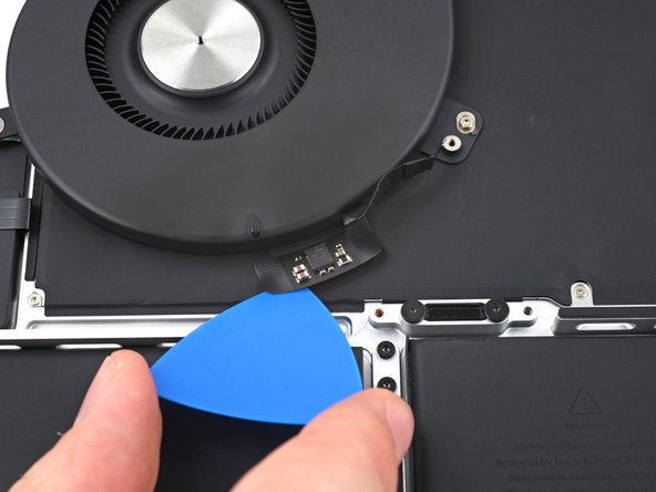
The right fan cable is just giving a gentle hug to the logic board.
– Grab your tweezers and gently tug the fan cable away from the logic board to free it from the sticky adhesive. You got this!
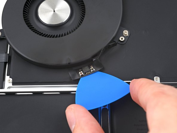
Step 54


– Time to give the left fan the same superstar treatment! Just repeat the disconnect and shuffle steps you rocked before.


Step 56


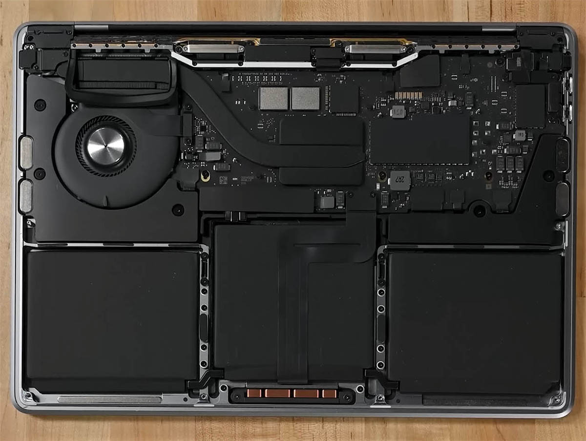
– Grab your T5 Torx driver and get ready to unleash those 11 screws holding the logic board hostage!


Step 58


– Wedge a spudger into the right side gap between the logic board and the frame.
– Give that spudger a little lift-up action to pop the logic board out of its snappy clips.
Tools Used
Step 59


– Wedge a spudger between the bottom of the logic board and the frame.
– Give it a little pry with the spudger to pop the logic board out of its snug clips.
Tools Used
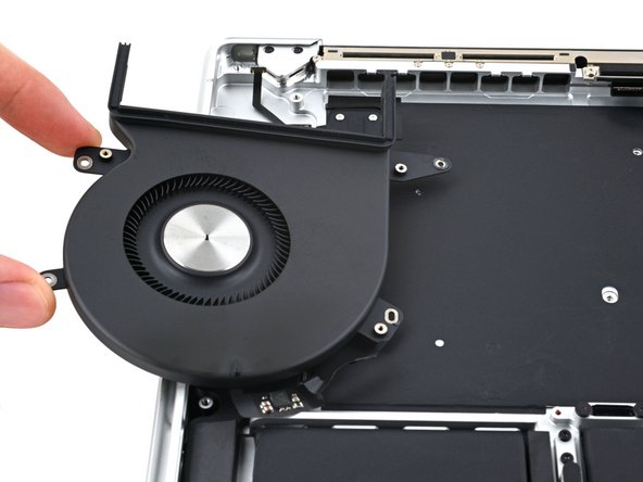
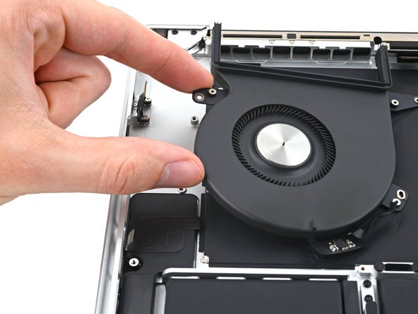
Step 60


– Carefully hoist the logic board from its right side to pop it out of its snug pegs like a toast from a toaster.
– Wiggle the logic board away from the left side of your gadget to free the HDMI and SDXC ports from their cozy nests in the frame.
– Lift off the logic board and bid it a fond farewell from its home.
Step 61


– When you’re putting things back together, don’t forget to do this: