
How to Replace MacBook Pro 15 Antenna Cover Guide
Duration: 45 minutes
Steps: 37 Steps
Heads up! Make sure you’ve got your tools ready and your game face on. Let’s nail this repair, step by stylish step!
Jazz up your device by swapping out that old antenna cover! This guide will show you the ropes and get your gear looking sharp in no time. Let’s make that device sparkle!


Step 2


– Whip out your screwdriver and unscrew the three snazzy 2mm Phillips screws holding the memory door in place.
– Give that memory door a gentle lift and a smooth slide towards yourself to free it from the embrace of the casing.
Step 3

– Unscrew the two 2.8 mm Phillips head screws that are chilling near the latch in the battery compartment.
Step 4

– Alright, let’s get those pesky screws out! You’ll be removing the following 6 screws:
Step 5

– Unscrew the four 3.2 mm PH00 Phillips screws hanging out on the port side of your laptop. Let’s get those little rascals out!
Step 6

– Give your computer a quick 90-degree twirl and unscrew the two cheeky 3.2 mm Phillips screws that are hanging out at the back. Easy-peasy!
Step 7

– Twist your computer 90 degrees once more and unscrew the four 3.2 mm Phillips screws from the side. Keep rocking it!
Step 8


Whoa, slow your roll! The upper case is still holding hands with the logic board via a ribbon cable. Easy does it!
– Start by lifting the rear end of the case and wiggle your fingers along the sides to loosen it up. Keep working around the case until the sides are free. You might have to give it a little wiggle dance to get the front of the upper case to let go.
– Watch out for the four stubborn plastic clips above the DVD slot and another tricky one above and to the left of the IR sensor. These clips are tough cookies that don’t like to let go without a bit of prying. Getting them back in place when reassembling can be just as pesky.
– Reassembly Tip: When putting it back together, give a good firm press right above where each clip sits until you hear a satisfying snap that tells you it’s snugly reseated in its home.
– Reassembly Tip: Those two middle DVD clips are notorious for not snapping back into place without a little extra help. To keep from bending the frame around the DVD slot, slide a plastic spudger into the slot right under where the clip needs to go. Push down gently until you hear that telltale snap.
Tools Used

Step 9


Heads up! You can swap out the hard drive without unplugging the keyboard, but you’ll need to juggle it upright to avoid interference—like a tech-savvy acrobat, giving you free hands to work the magic on the drive!
Watch out for the sneaky keyboard-trackpad ribbon cable when you’re freeing the rear of the upper case near the hinge. It’s super easy to accidentally warp the screw receivers flanking the keyboard—handle with care!
– Unplug the trackpad and keyboard ribbon cable from the logic board, peeling off any tape that gets in your way.
– Time to say goodbye to the upper case—lift it off!
Step 10

– Unhook those antenna cables from the Airport Extreme card, you might find two or three depending on your model. If there’s a third amigo just chilling there capped with a sleek black tube, it’s just hanging out, unused.
– Props to Apple for dropping in a handy label to show where each colorful antenna cable should reconnect. It’s like a cheat sheet, so peek at that when you’re plugging the cables back in.
Step 11

– Hey there, tech-savvy friend! Gently guide the Airport antenna cables out of their groove in the left speaker like you’re untangling a delicate necklace. You’ve got this!
Step 12

– Gently slide the iSight cable to the left and out of its connector on the logic board. You’ve got this!

Step 14

– Pop off the inverter cable from the left I/O board by slipping a spudger underneath the cable and giving it a gentle lift. Easy peasy!
Tools Used
Step 15


– Unplug the display data cable from the logic board like a boss.
– Peel off the foam bumper from atop the right hinge of the display with flair.
Step 16

– Time to unscrew that silver 9.2 mm T6 Torx that’s holding the ground loop of the display data cable snug against the casing. Let’s get that cable free!

Step 18

– Get a firm grip on both sides of the display assembly and gently lift it away from the computer like you’re lifting a treasure chest out of the sand.
Step 19


– Unscrew the two 4.5 mm Phillips screws chillin’ in the lower left and right corners of the display. Each screw rocks a .8 mm thick head. Get ’em out and move on!
Step 20


Whoa there, partner! Keep that spudger away from the space between the plastic strip and the rear bezel, okay?
– Wedge the flat end of your spudger just right between that sneaky plastic strip clinging to the rear bezel and the front bezel. It’s like they’re having a secret meeting and you’re about to break it up!
– Keep that spudger in place and give it a little twist away from the display. It’s like you’re telling the bezels, ‘Hey, need some space here!’
– Saunter down the right edge of the display, continuing your spudger-twisting action until the rear bezel has politely stepped back from the front bezel all the way along. It’s all about even separation, keep it cool and steady!
Tools Used


Step 22


– Place the flat end of a spudger into the gap between the rear display bezel and the clutch cover.
– Rotate the spudger to loosen the lower edge of the rear display bezel from the clutch cover.
– Continue working along the lower edge of the rear bezel until it is uniformly detached from the clutch cover.
Tools Used
Step 23


– Alright, you’ve got the right and bottom edges of the rear bezel playing nice and starting to separate from the front bezel. Let’s keep the good vibes rolling! Grab your spudger and gently pop the rear bezel off the tabs near the lower right corner of the display. You’re doing great!
Tools Used
Step 24


– Wedge the flat end of your spudger between the front bezel and that sneaky plastic strip clinging to the rear bezel near the bottom corners of the display.
– Give your spudger a little twist toward the rear bezel to show it who’s boss and start the separation process.
– If it’s being stubborn, keep on prying along the left edge to pop the rear bezel off the tabs holding onto the front display bezel.
Tools Used

Step 26

– Gently nudge the LED driver board out of the clutch cover using the tip of a spudger. You’ve got this!
Tools Used
Step 27

– Gently unplug that backlight cable by pulling its connector away from the socket on the LED driver board. You got this!
Step 28

Handle the LED driver cable ground loop with care—it’s super thin and delicate, like a spider’s web!
– Unplug the LED driver cable by gently tugging its connector from the socket on the inverter board. Easy does it!
– Take off the LED driver board and just put it aside for now. Keep it safe!
Step 29


– Whisk away the two kapton tape guardians to unveil the display data cable.
– Banish the strip of tape that’s keeping the iSight cable too cozy with the LCD.
– Gently convince the three antenna straps to abandon their posts at the lower edge of the LCD.

Step 31

– Unscrew the two Phillips screws that are keeping the ground straps for the display data cable and LED driver board cable snug against the clutch cover.

Step 33

– Unscrew the trio of Phillips screws hiding behind the antenna straps at the bottom of your display. It’s like a little game of hide and seek with your screws!
Step 34

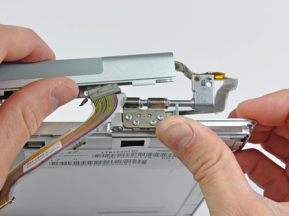
– Kick things off by wedging the flat end of your trusty spudger into the nook between the clutch hinge and the clutch cover, right where those sneaky cables make their exit.
– Keep the spudger party going by gently prying the clutch assembly off the hinge, while simultaneously using a plastic opening tool to widen that gap between the clutch cover and the front display bezel. It’s like a little dance for your hands!
– Sashay down the length of the clutch cover, gradually separating the sticky adhesive. It’s like peeling off a band-aid, slow and steady wins the race!
Tools Used
Step 35

– Gently nudge the clutch assembly off each of the clutch hinges and bid it farewell from the display.
Step 36

– Unscrew the five cheeky little Phillips screws that are keeping the plastic antenna cover cozy against the clutch cover.
Step 37

– Gently remove the antenna cover from the clutch cover, taking care not to harm those antenna cables.


