
How to Replace MacBook Pro 15 Antenna Cover: Step-by-Step DIY Tutorial
Duration: 45 minutes
Steps: 35 Steps
Ready to give your device a fresh new look? Swap out that worn-out antenna cover following this simple guide!
Step 2

– Unscrew the three identical Phillips screws holding the memory door in place.
Step 3

– Lift that memory door up with style, get a good grip on it, and slide it towards you while pulling it away from the casing. Keep it cool, you got this!
Step 4

– Take out those two 2.8 mm Phillips screws hanging out in the battery compartment by the latch. You’ve got this!
Step 5

– Time to get your screwdriver ready! Let’s tackle those 6 screws and get this repair party started!
Step 6

– Let’s get started by taking out those four 3.2 mm Phillips screws on the port side of your computer. You’ve got this!
Step 7

– Twist the computer 90 degrees and pop out the two 3.2 mm Phillips screws from the back.
Step 8

– Give your computer a little twist and turn it 90 degrees once more. Now, let’s tackle those four 3.2 mm Phillips screws hanging out on the side. Time to show them who’s boss!
Step 9

Take it easy when removing the upper case! It’s connected to the logic board with a ribbon cable, so give it a gentle nudge instead of a quick yank. Your device will thank you!
– Time to show that case who’s boss! Lift up at the back and smoothly slide your fingers along the sides, releasing the case like a pro. Once the sides are free, get ready to groove – gently rock the case up and down to release the front part of the upper case (watch out for those sneaky secret clips!).
Step 10

– Pop off the trackpad and keyboard ribbon cable from the logic board, and peel off any tape in the way.
– Lift off the upper case.
Step 11

– Unplug the three antenna cables from the Airport Extreme card. It’s like giving your device a little break!
– Apple has thoughtfully provided a handy label to guide you on where each colorful antenna cable should go. Just keep an eye on it when you’re plugging those cables back in!
Step 12

– Free those Airport antenna cables from their cozy spot in the left speaker channel.
Step 13

– Gently slide the iSight cable to the left and pop it out of its connector on the logic board. You’ve got this!
Step 14

– Gently detach the inverter cable from the logic board by sliding a spudger underneath and giving it a little lift. You’ve got this!
Tools Used

Step 15

– Gently wiggle the display data cable to the side and disconnect it from the logic board. You’ve got this!
Step 16

– Unscrew the shiny silver T6 Torx that’s keeping the ground loop of the display data cable snug against the casing.

Step 18

– Gently grab hold of the display assembly from both sides, giving it a little lift up and away from the device.
Step 19


– Unscrew the two adorable little 5 mm Phillips screws hugging the lower left and right corners of the display (a dynamic duo of screws).
Step 20


– Pop the flat end of your spudger just between the sneaky plastic strip clinging to the rear bezel and the front bezel. It’s like you’re trying to sneak into a cookie jar without getting caught!
– Keep that spudger in place and give it a little twist away from the display. It’s like turning a key to unlock the secrets of the bezels!
– Now, dance along the left edge of the display with your spudger until the rear bezel pops off from the front bezel like a smooth magician revealing a trick.
Tools Used
Step 21


– Slide the flat end of a spudger perpendicular to the display’s face, between the plastic strip on the back and the front bezel.
– With the spudger still in place, twist it away from the display to pop the front and rear bezels apart.
– Move along the right edge of the display until the back bezel is evenly separated from the front bezel.
Tools Used
Step 22


– Get ready to insert the flat end of a spudger between the front bezel and the plastic strip attached to the rear bezel near the screw holes at the bottom corners of the display.
– Give your spudger a little twist towards the rear bezel to gently separate it from the front bezel.
– If needed, make the gap between the lower edge of the rear bezel and the clutch cover a bit bigger until the two parts come apart completely.
Tools Used

Step 24

Handle with care! The display inverter is super thin and fragile, and it can easily break. If you need help, you can always schedule a repair.
– Gently pop the inverter board out of its clutch cover nest.
Step 25

– To disconnect the LCD backlight from the inverter, just gently pull the connector away from the inverter board. Easy peasy!
Step 26

Give some love and gentle care to the inverter cable ground loop – it’s a super delicate wire, so handle with care!
– Gently pull the inverter cable’s connector away from the inverter socket to disconnect it. You’ve got this!
Step 27


– Let’s kick things off by removing those pieces of yellow kapton tape from the bottom left corner of the display.
– Next up, get ready to peel off those three green antenna ground straps from the copper tape along the bottom edge of the LCD.
– Now, it’s time to bid farewell to the piece of tape that’s been keeping the camera cable attached to the LCD.
Step 28


– Time to free the cables! Start by removing the tape that’s securing the display data cable and camera cable connectors.
– Now, gently peel the camera cable away from the foam tape along the top edge of the LCD. It’s like peeling a banana—easy does it!
Step 29


– With care and finesse, gently tug the camera cable away from its cozy socket on the camera board.
– Give a good, firm tug to detach the display data cable connector from its snug socket on the LCD screen.
– Make sure to pull both cables in a smooth, parallel motion towards the friendly face of the logic board.
Step 30


– Got a Core Duo machine? Check out picture 1 and pop out those three Phillips screws holding the clutch assembly to the front display bezel near the display data cable.
– Rocking a Core 2 Duo Model A1211? Look at picture 2 and take out those two Phillips screws connecting the clutch assembly to the lower edge of the front display bezel near the display data cable.
Step 31

– Time to tackle that tiny Phillips screw hiding behind the display data cable! Go ahead and remove it with a gentle twist.
– Now, let’s slide that small rectangular steel bracket away from the right clutch hinge. It’s like giving it a little nudge to say ‘see you later!’

Step 33


If you find it necessary, go ahead and give the same routine a whirl on the right side of the clutch assembly.
Step 34

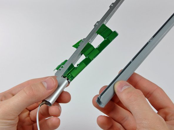
– Unscrew the five cheeky little Phillips screws holding down the plastic antenna cover inside the clutch cover. It’s like uncovering hidden treasure!
Step 35

– Gently wiggle the antenna cover off the clutch cover. Watch out for those sneaky antenna cables!

