
How to Replace MacBook Pro 15 Antenna Cover – Step-by-Step Guide
Duration: 45 minutes
Steps: 34 Steps
Heads up, tech whiz! Make sure you’ve got your tools ready and your workspace clear. Let’s make this repair a smooth ride!
Give your gadget a makeover by swapping out that old antenna cover with this snazzy guide. Let’s make your device look sleek and new again!

Step 2

– Unscrew the trio of identical Phillips screws securing the memory door. Group hug!
– Keep a record of which screws came from which spots. It’s like a puzzle, and you’re the puzzle master!
Step 3

– Gently lift up the memory door just enough to get a good grip, then slide it toward you like you’re pulling a tablecloth in a magic trick—away from the casing and voila!
Step 4

– Unscrew the two Phillips screws chilling by the latch in the battery compartment. Let’s keep it cool and easy!
Step 5

– Alright, let’s unscrew the following 6 screws:
Step 6

– Unscrew those four fabulous Phillips screws on the port side of your device, and let the repair party begin!
Step 7

– Give your computer a little twirl, turning it 90 degrees, and then whisk away the two Phillips screws chilling at the back.
Step 8

– Twist that computer another cool 90 degrees and unscrew the four Phillips screws hanging out on the side. Keep it going, you’re doing great!
Step 9

Whoa there, hold up! Don’t just rip off the upper case like it’s a band-aid! There’s a sneaky ribbon cable connecting it to the logic board. Let’s keep it all in one piece, shall we?
– Start by lifting the rear end of the case and wiggle those fingers along the sides to loosen it up. Keep moving until the sides are free. You might have to give the case a little rock-and-roll motion to unhook the front. Hang in there, this part can be a bit of a challenge! Just above the DVD reader, you’ll find 4 sneaky tabs that need a gentle pull upwards.
– Heads up! The two tiny tongues on the front left side of the upper case might get a bit bent out of shape during the removal. No stress, just give them a little tweak back into shape to make sure they slip into the lower case grooves smoothly when putting it back together.
Step 10

– Unhook the trackpad and keyboard ribbons from the logic board. Feel free to peel off any tape that’s in your way!
– Now, lift off the upper case and set it aside. You’re doing great!
Step 11

– Unhook those two snazzy antenna cables from the Airport Extreme card like a boss.
– Remember, the white antenna cable struts its stuff on the left side of the Airport Extreme card.
Step 12

– Unroute those funky Airport antenna cables from their groove in the left speaker. It’s like setting them free!
Step 13

– Gently wiggle the iSight, inverter, and left fan cables free from the logic board. Just pull in the direction the cables are facing, and they’ll pop right out. Easy peasy!

Step 15

– Unscrew the snazzy silver T6 Torx screw that’s holding the ground loop on the display data cable to the casing. It’s just a little twist and shout!

Step 17

– Grab hold of the display on both sides and gently lift it up and away from the computer like you’re lifting a slice of pizza from the box.
Step 18


– Unscrew the two 5 mm Phillips screws chilling in the lower left and right corners of the display. Just two screws, and you’re doing great!
Step 19


Remember, keep that spudger away from the space between the plastic strip and the back casing—it’s a no-fly zone!
– Wedge the flat end of your spudger between the plastic strip on the rear bezel and the front bezel. Make sure it’s perpendicular to the display face for a perfect fit.
– With your trusty spudger in place, give it a little twist away from the display. This slick move will start separating the front and rear bezels.
– Keep cruising along the left edge of the display, gently working your spudger as you go, until the rear bezel and the front bezel are hanging out separately.
Tools Used

Step 20


– Slide the flat end of your spudger between that sneaky little plastic strip on the rear bezel and the front bezel. Make sure it’s perpendicular to the display—like a little spudger barrier!
– Keep that spudger in place and give it a twist away from the display. This little maneuver will start to part the front and rear bezels like a magic trick!
– Continue your spudger journey along the right edge of the display, prying as you go, until the rear bezel pops off from the front bezel like they’re breaking up!
Tools Used
Step 21


– Wedge the flat end of your trusty spudger between the sassy front bezel and the clingy plastic strip near those sneaky screw holes at the bottom corners of the display.
– Give your spudger a little twist toward the rear bezel to show it who’s boss and pry them apart.
– If things are still a bit snug, gently widen the gap between the rear bezel’s lower edge and the clutch cover until they’re totally doing their own thing.
Tools Used

Step 23

Heads up! The display inverter is super slim and super fragile, almost like a secret agent of circuit boards! Handle with care to keep it in tip-top shape.
– Gently hoist the inverter board out of the clutch cover like you’re lifting a crown. Easy does it, champ!
Step 24

– Unplug the LCD backlight from its inverter by gently sliding its connector off the inverter board. Easy peasy!
Step 25

Take it easy around that inverter cable ground loop! It’s as delicate as a spider’s silk.
– Unplug the inverter cable by gently sliding its connector out of the socket on the inverter. Easy peasy!
Step 26


– Whisk away the yellow kapton tape from the sneaky bottom left corner of the display.
– Unstick those three cheeky green antenna ground straps from the copper tape along the bottom edge of the LCD.
– Liberate the tape holding the camera cable hostage to the LCD.
Step 27


– Whisk away those sneaky pieces of tape hiding over the display data cable and camera cable connectors.
– Gently persuade the camera cable to unstick itself from the foamy embrace along the top edge of the LCD.
Step 28


– Ease that camera cable out of its comfy socket on the camera board like you’re coaxing a shy kitten from under the bed.
– Give the display data cable connector a gentle tug away from its home on the LCD. It’s moving day!
– Slide both cables parallel to the face of the logic board as if you’re smoothing out a wrinkle on your favorite shirt.
Step 29


– Got a Core Duo device? Chill and check out picture 1. You’ll need to whisk away three Phillips screws that are chilling by the lower edge of the front display bezel, right near the display data cable.
– Rocking a Core 2 Duo Model A1211? Awesome! Peep picture 2 and gently remove two Phillips screws that are hanging out at the lower edge of the front display bezel, close to the display data cable.
Step 30

– Whisk away that tiny Phillips screw hiding behind the display data cable. Sneaky little fellow!
– Now, gently slide out the small rectangular steel bracket from its cozy spot next to the right clutch hinge. Easy does it!


Step 33

– Unscrew the five cheeky little Phillips screws holding the plastic antenna cover in place inside the clutch cover. It’s like a little puzzle waiting for you!
Step 34

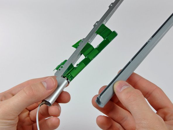
– Gently tug the antenna cover away from the clutch cover, watch out for those sneaky antenna cables!


