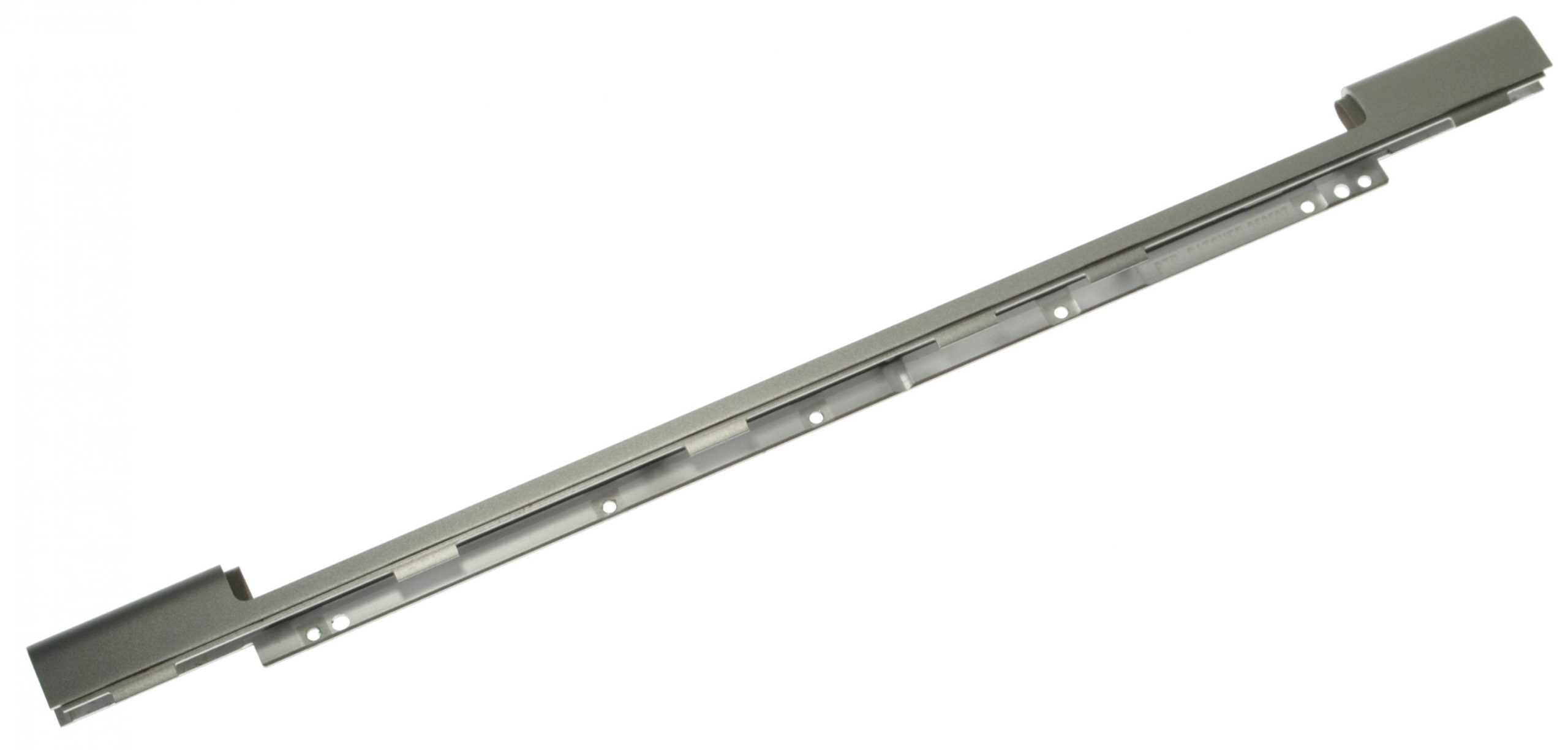
How to Replace MacBook Pro 15 Clutch Cover – DIY Guide
Duration: 45 minutes
Steps: 40 Steps
Heads up! Make sure to handle this part with extra care, it’s a bit tricky but you’ve got this!
Get ready to swap out that worn-out aluminum clutch cover! Follow this guide to make the replacement process a breeze. If you find yourself needing assistance, feel free to schedule a repair.


Step 2


– Unscrew the three super cool 2mm Phillips screws holding the memory door in place.
– Give the memory door a little lift and slide maneuver towards yourself to free it from its cozy home.
Step 3

– Unscrew the two 2.8 mm Phillips party crashers chilling in the battery compartment near the latch.
Step 4

– Time to get your screwdriver ready! Let’s tackle those 6 screws and get this repair party started!
Step 5

– Unscrew the four 3.2 mm PH00 Phillips screws on the port side of your computer. Let’s get those screws out and say goodbye to any barriers standing in the way of your repair journey!
Step 6

– Give your computer a little twist and turn it 90 degrees! Now, let’s dive into the back and unscrew those two 3.2 mm Phillips screws hanging out there. You’ve got this!
Step 7

– Give your computer a little twist and turn it 90 degrees once more. Now, let’s tackle those four 3.2 mm Phillips screws hanging out on the side. Time to show them who’s boss!
Step 8


Take it easy when removing the upper case! It’s connected to the logic board with a ribbon cable, so give it a gentle touch.
– Start by gently lifting the back of the case and using your fingers to glide along the sides, freeing it bit by bit. Once the sides are loose, give the case a little rock up and down to release the front of the upper case.
– You’ll find four sneaky plastic clips hiding above the DVD slot, plus another one above and to the left of the IR sensor. These little guys can be quite the challenge to disengage without some gentle persuasion. Just a heads up, they might also be tricky to re-engage when you’re putting everything back together.
– Reassembly Tip: When it’s time to put things back, give a firm press on the top case right above each clip until you hear a satisfying snap, ensuring they’re snug in their spots.
– Reassembly Tip: The two center DVD clips can be a bit stubborn and may not pop back into place without a little help. Instead of forcing it, try supporting the frame by sliding a plastic spudger into the DVD slot directly beneath the clip location until it fits snugly. Then, press down until you hear that reassuring snap.
Tools Used

Step 9


Heads up! You can swap out the hard drive without having to detach the keyboard from the chassis. Just keep it propped up so it doesn’t get in your way while giving your hands the freedom to tackle that drive removal like a pro!
When you’re carefully detaching the keyboard-trackpad ribbon cable, make sure the back of the upper case is free from the hinge area. It’s super easy to accidentally bend those screw receivers on either side of the keyboard, so keep an eye on it!
– Carefully unplug the trackpad and keyboard ribbon cable from the logic board, peeling off any tape that might be in the way.
– Gently lift off the upper case.
Step 10

– First things first, gently disconnect the two or three antenna cables from the Airport Extreme card. Depending on your model, you might find one of those cables is just hanging out, capped with a black shrink tube, waiting for its moment to shine.
– Lucky for you, Apple has made it super easy by including a handy label that shows where each color antenna cable should go. Just keep an eye on that when you’re plugging everything back in!
Step 11

– Untangle the Airport antenna cables from their cozy nest in the left speaker.
Step 12

– Gently slide the iSight cable to the left and pop it out of its connector on the logic board. Easy peasy!
Step 13

– Hold the display steady with one hand while you carefully take out the screws listed below:
Step 14

– To disconnect the inverter cable from the left I/O board, gently slide a spudger under the cable and lift upwards.
Tools Used
Step 15


– Unplug the display data cable from the logic board like a boss!
– Peel off the foam bumper sitting on top of the right hinge of the display. It’s like removing a tiny pillow from a tiny bed!
Step 16

– Take out that shiny 9.2 mm T6 Torx screw that’s holding the ground loop of the display data cable to the case. You’ve got this!

Step 18

– Grab both sides of the display assembly and lift it like you’re picking up a slice of pizza out of the box.
Step 19


– Unscrew the 4.5 mm Phillips screws chilling in the lower left and right corners of the display (you’ll find two of these funky little screws). Just a heads up, they sport a .8 mm thick head. Get ’em out and move on to the next step, you’re doing great!
Step 20


Keep your spudger away from the space between the plastic strip and the back casing—not there, buddy!
– Pop in the flat end of a spudger right between that sneaky plastic strip on the rear bezel and the front bezel. Make sure it’s perpendicular to the display face, like a little spudger soldier standing guard.
– While keeping the spudger in place, give it a twist away from the display. It’s like opening a jar of pickles, but with bezels!
– Saunter down the right edge of the display, prying as you go, until the rear bezel loosens up from the front bezel like they’re breaking up.
Tools Used


Step 22


– Place the flat end of a spudger into the gap between the rear display bezel and the clutch cover.
– Rotate the spudger to loosen the lower edge of the rear display bezel from the clutch cover.
– Proceed to detach the lower edge of the rear bezel from the clutch cover, ensuring it is removed evenly.
Tools Used


Step 24


– Slide the flat end of your trusty spudger between the front bezel and the plastic strip that’s hanging out with the rear bezel near those screw holes at the bottom corners of the display.
– Give your spudger a little twist toward the rear bezel to help them part ways.
– If it’s feeling a bit stubborn, keep working on separating the left edge of the rear bezel from the tabs on the front display bezel.
Tools Used

Step 26

– Gently use the spudger’s tip to pop the LED driver board out of the clutch cover like a pro!
Tools Used
Step 27

– Gently unplug the backlight cable by pulling its connector away from the LED driver board socket. You’ve got this!
Step 28

Hey there! Just a heads-up: handle the LED driver cable ground loop with care. It’s a super thin, delicate wire that’s easy to break. You’ve got this!
– Gently wiggle the connector of the LED driver cable out of its socket on the inverter board like you’re coaxing a kitten out of hiding.
– Carefully lift the LED driver board off its throne and place it to the side, safe and sound.
Step 29


– Yank off the two snazzy pieces of kapton tape that are chillin’ over the display data cable.
– Strip away the tape that’s heroically guarding the iSight cable to the LCD like a silent sentinel.
– Peel back the trio of antenna straps from the lower edge of the LCD with the finesse of a ninja.

Step 31

– Unscrew the two Phillips screws that are keeping the ground straps for the display data cable and LED driver board cable snug against the clutch cover. Let’s set those little guys free!
Step 32

– Unscrew the sneaky little Phillips that’s chilling behind the display data cable. You got this!
Step 33

– Whip out your Phillips screwdriver and unscrew the trio of screws hiding behind the antenna straps at the bottom edge of the screen. It’s like a mini treasure hunt!
Step 34

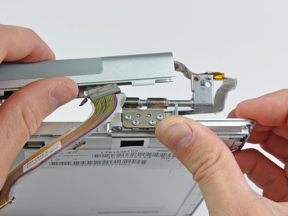
– Start by wedging the flat end of a spudger into the cozy gap between the clutch hinge and clutch cover right at the spot where the cables make their grand exit.
– While gently nudging the clutch assembly away from its buddy the clutch hinge with your trusty spudger, grab a plastic opening tool to widen the gap between the clutch cover and the front display bezel like a pro.
– Saunter along the entire length of the clutch cover, easing the adhesive apart with the finesse of a skilled technician.
Tools Used
Step 35

– Slide that clutch assembly off each hinge like a pro and whisk it away from the display. You’ve got this!
Step 36

– Unscrew the five sneaky little Phillips screws that are keeping the plastic antenna cover cozy inside the clutch cover.
Step 37

– Gently remove the antenna cover from the clutch cover, taking care not to snag those delicate antenna cables.
Step 38

– If needed, gently peel the antenna leads away from the sticky stuff holding them to the clutch cover.
– Carefully detach the antenna cables from the clutch cover, making sure to avoid any mishaps with the three antenna straps.
Step 39

– Gently detach the antenna cables from the clutch cover. Watch out for those three nifty antenna straps—we don’t want any oopsies!
Step 40

– Hang in there, the clutch cover is still in place!


