How to Replace MacBook Pro 15 Front Display Bezel
Duration: 45 minutes
Steps: 41 Steps
Hey there, tech whiz! Just a heads-up to keep things smooth and snappy, make sure you’ve got the right tools and parts before you dive in. If things get tricky, remember you can always schedule a repair with us. Happy fixing!
Follow this groovy guide to swap out a wonky front display bezel. If you need help, you can always schedule a repair.
Step 2

– Whip out your Phillips screwdriver and remove the trio of twin screws from the memory compartment door.
– Keep track of which screws came from where—it’s like a little puzzle for when you put things back together!
Step 3

– Give the memory door a little nudge up to get a good hold on it, then slide it toward yourself and pull it free from its cozy home.

Step 5

– Unscrew the following 6 screws:
Step 6

– Unscrew the four fabulous Phillips screws chilling on the port side of the computer.
Step 7

– Twist your device a cool 90 degrees and unscrew the two Phillips screws chilling at the back. Easy peasy!
Step 8

– Give your computer another cool spin to the right (90 degrees to be exact) and unscrew those four Phillips screws from the side. We’re getting there!
Step 9

Hold up, partner! Don’t just rip off the upper case like it’s a band-aid. There’s a sneaky ribbon cable connecting it to the logic board. Let’s keep it chill and handle it with care.
– Start by lifting from the back of the case and wiggle your fingers along the sides to loosen it up. Keep going until the sides are free. You might have to give it a little shimmy up and down to release the front part of the upper case. This part can be a bit of a pickle! Just above the DVD reader, there are 4 sneaky tabs that need a gentle tug outwards.
– Watch out for the two tiny tabs on the front left of the upper case—they might get a bit bent out of shape as you lift off the upper case. When you’re putting it back together, you might have to straighten them out so they’ll slip back into the grooves on the lower case without a fuss.
Step 10

– Unplug the trackpad and keyboard ribbon cables from the logic board, peeling off any tape that gets in the way.
– Lift off the upper case with a flourish.
Step 11

– Unplug those two snazzy antenna cables from the Airport Extreme card.
– The white antenna cable struts its stuff on the left side of the Airport Extreme card.
Step 12

– Wiggle those Airport antenna cables out of their groove in the left speaker with a little flair!
Step 13

– Gently pull the iSight, inverter, and left fan cables away from the logic board. It’s like unplugging a tiny, delicate spaghetti from the brains of the operation. Easy does it!

Step 15

– Unscrew the shiny T6 Torx screw that’s keeping the ground loop of the display data cable attached to the casing. Let’s get that little guy free!

Step 17

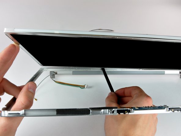
– Grab each side of the display assembly and gently lift it up and away from the computer. You’re doing great!
Step 18


– Unscrew the two cheeky 5 mm Phillips screws chilling on the lower left and right corners of the display. Just two screws, easy peasy!
Step 19


– Wedge the flat end of your spudger between the rear bezel’s plastic strip and the front bezel. Keep it perpendicular to the display face for a slick entry!
– With the spudger in place, give it a twist away from the display to start the magic of separating the front and rear bezels.
– Glide along the left edge with your spudger, prying gently as you go, until the rear bezel and front bezel are separated like a smooth dance move.
Tools Used

Step 20


– Pop in the flat end of your spudger just between that sneaky plastic strip clinging to the rear bezel and the front bezel. Make it perpendicular to the display face—like it means business!
– Keep that spudger in place and give it a little twist away from the display. This is your magic move to get those front and rear bezels to break up.
– Cruise down the right edge of the display, and keep at it until the rear bezel loosens up and gives some space to the front bezel, nice and even.
Tools Used
Step 21


– Wedge the flat end of your spudger between the front bezel and the plastic strip clinging to the rear bezel near the screw holes at the display’s bottom corners.
– Twist your spudger towards the rear bezel to coax it away from the front bezel with a bit of spudger magic.
– If needed, gently widen the gap between the lower edge of the rear bezel and the clutch cover until they part ways completely.
Tools Used

Step 23
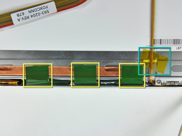

– Wrestle off those sticky yellow kapton tape pieces from the bottom left corner of the display. Show them who’s boss!
– Unstick the tapes that are keeping the display data cable and camera cable too cozy with the display.
– Peel off the three green antenna ground straps from the copper tape along the LCD’s bottom edge like you’re peeling a banana.
– Liberate the piece of tape that’s holding the camera cable hostage to the LCD.
Step 24

– Gently unstick the camera cable from the foam tape along the top edge of the LCD. It’s like peeling a banana—smooth and easy!
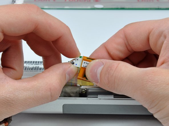
Step 25

Slide the cable out parallel to the LCD’s face. Keep it smooth and steady, like you’re skimming the surface of a calm lake.
– Pop the ZIF connector bar up with the pointy end of a spudger to free the camera cable like a magic trick!
– Carefully slide the camera cable out of its home on the camera board like you’re pulling a rabbit out of a hat!
Tools Used
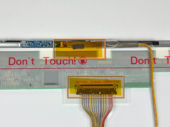
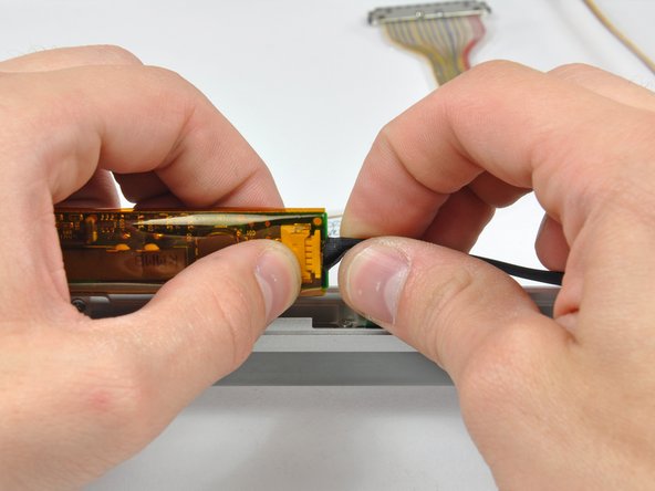
Step 26

Slide the connector out parallel to the LCD’s surface. Keep it smooth and steady, champ!
– Gently slide the display data cable connector out of its cozy little socket on the LCD. It’s like unplugging a tiny electronic flower from its pot!
Step 27


– Unscrew the eight snazzy black Phillips screws that are chilling on the left and right sides of the display. Just twist them out and set them aside. Easy peasy!
Step 28

The adhesive here is sneakily clinging to a slim steel border circling your LCD. While you’re coaxing the LCD off the front panel, make sure you’re actually peeling it away from the steel trim, not just tugging at the screen. Keep it smooth and steady!
Alright, it’s showtime for the LCD! You’re about to dive into the sticky situation of detaching the LCD from the adhesive on the top and bottom edges of the front bezel. A little heat gun action might just be your best buddy here, warming up that glue and making sure your LCD comes out as cool as a cucumber, without any oopsies!
Tools Used
Step 29

– Glide along the top edge of the LCD and gently coax the steel strip to part ways with the front bezel. Keep the vibe light and the movements smooth!
Step 30

– With the top edge now free, gently lift the LCD out of the front bezel just enough to create some space for prying the steel strip along the lower edge of the LCD away from the front bezel.
– Carefully pry along the lower edge of the LCD until it pops free from the adhesive holding it to the front bezel.
Step 31

– Gently hoist the inverter from its cozy spot in the clutch cover.
– Unplug the LCD backlight connector with a smooth wiggle from its home on the inverter board.
Step 32

– Hoist that LCD out of the front bezel like you’re lifting a treasure chest, but watch out for those sneaky cables trying to tag along!
Step 33

Careful there! Gently ease out the inverter cable, but don’t tug too hard. Remember, it’s got a super delicate ground loop that breaks easier than a cookie crumble!
– Hoist the inverter out of its cozy clutch cover home.
– Unplug the inverter cable by gently tugging it away from its socket on the inverter board—like pulling a leaf off a tree!
– Remove the inverter and set it aside like a treasure.
Step 34

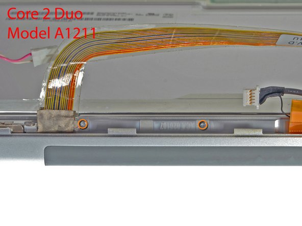
– Got a Core Duo gadget? Check out picture 1 and whisk away three Phillips screws that are cozying up the clutch assembly to the lower edge of the front display bezel near the display data cable.
– Rocking a Core 2 Duo Model A1211? Peep picture 2 and gently remove two Phillips screws that are hanging out connecting the clutch assembly to the lower edge of the front display bezel near the display data cable.
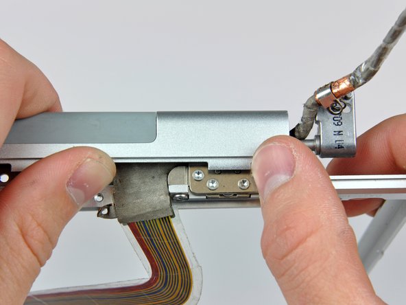
Step 35

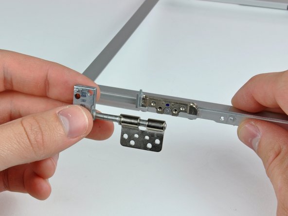
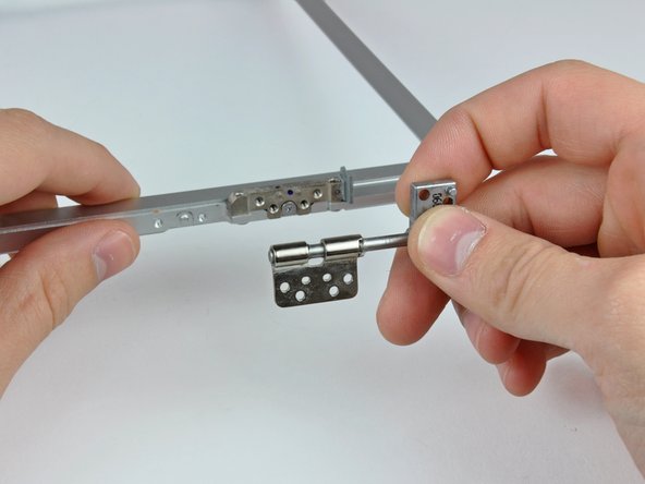
– Unscrew the lone black Phillips screw hiding behind the display data cable. It’s just chilling there!
– Gently slide the tiny steel bracket away from the right clutch hinge and lift it off the clutch assembly. It’s like a mini treasure hunt!
Step 36

– Unscrew the trio of Phillips screws chilling by the clutch cover near the inverter/camera cable.

Step 38

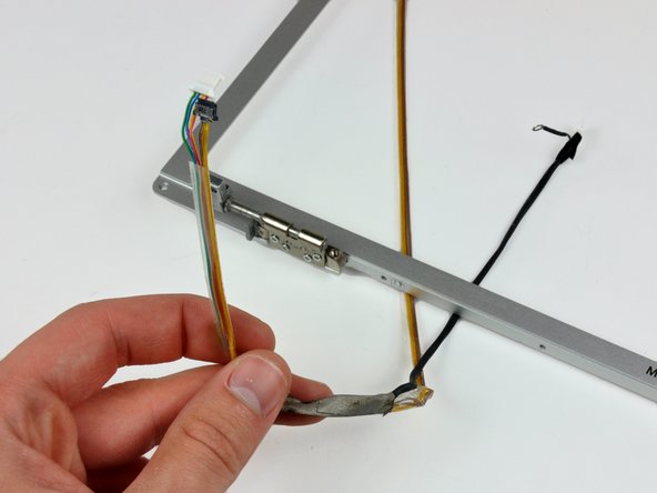
– Unravel the display data and inverter/camera cables from the clutch hinges and carefully remove them. It’s like untangling your headphones, but a bit more techy and fun!