
How to Replace MacBook Pro 15 Lower Case
Duration: 45 minutes
Steps: 46 Steps
Heads up, tech whiz! Make sure you’ve got your tools ready and your workspace clear. Let’s make this repair a breeze!
Swapping out the metal bottom case.
Step 2

– Unscrew the trio of snazzy Phillips screws chillin’ on the memory door.
Step 3

– Gently hoist the memory door just enough to get a solid grip, then shimmy it toward yourself and away from its snazzy casing.
Step 4

– Unscrew the two cheeky 2.8 mm Phillips screws chilling in the battery compartment near the latch.
Step 5

– Time to unscrew some stuff! Grab your tools and remove these 6 screws:
Step 6

– Unscrew the four 3.2 mm Phillips screws on the port side of the computer. Let’s get those screws out and the party started!
Step 7

– Twist your device 90 degrees and unscrew the two 3.2 mm Phillips screws at the back. Easy peasy!
Step 8

– Give your computer a little twirl—another 90 degrees to be exact—and whisk away those four 3.2 mm Phillips screws from the side. You’re doing great!
Step 9

Hold your horses! Don’t just rip off the upper case like it’s a band-aid. There’s a sneaky ribbon cable connecting it to the logic board. Let’s keep it chill and gentle, okay?
– Start by lifting the back of the case and slide your fingers along the sides to loosen it. Continue around the sides until they are free. You might need to gently wiggle the case up and down to release the front part of the upper case, as it’s secured by some sneaky hidden plastic clips.
Step 10

– Unhook the trackpad and keyboard ribbons from the logic board, peeling off any tape that’s in the way.
– Whisk away the upper case.
Step 11

– Unhook the zesty orange SuperDrive ribbon cable from the logic board, peeling off any tape that’s in the way.
Step 12

– Alright, let’s unscrew these 4 little rebels:
Step 13

– Hoist the optical drive right out of the computer like you’re lifting a trophy. Off it goes!
Step 14

– Unplug the hard drive and ExpressCard connectors from the logic board on the left side like a boss!
Step 15

– Slide out those iSight and display data cables from the logic board like a boss, peeling off any tape that dares stand in your way.
Step 16

– Unplug those eight connectors! Just slide a spudger under each cable and give it a gentle lift. Easy-peasy!
Tools Used

Step 17

– Unscrew the shiny silver T6 Torx screw that’s keeping the ground loop of the display data cable tied down to the casing. Let’s set that little guy free!
Step 18

– Unscrew the lone T6 Torx screw that’s holding the snazzy clear plastic shield over the right ambient light sensor.
– Gently lift away the clear plastic shield to free the right ambient light sensor.
Step 19

– Gently peel off the orange Kapton tape holding the right thermal sensor cable to the logic board. It’s like uncovering hidden treasure!
Step 20

– Time to unscrew some stuff! Remove these 15 screws coming up:
Step 21

– Keep one hand on the logic board, and with your other hand, give that left fan a gentle lift from its cozy spot. You’ll spot some sneaky black tape clinging onto the heat sink. Go ahead and peel that tape off gently as you lift the fan.
– Just park that fan right above the Airport card—no need to take it out of the computer completely. Keep it chill right there!

Step 23

– Gently hoist up the left side of the logic board and pop off the gray and black power cable from the board’s bottom. Easy does it!
Step 24

Alright, it’s time to jazz up your MacBook Pro by giving it a fresh thermal compound makeover! Follow our cool guide on Applying Thermal Paste to get the processor and heat sink looking sharp and performing cool.
– Grab the logic board on the left and the skinny part, then give it a little twist to lift it out of the lower case.
Step 25

Should you find yourself needing to reattach the heat sink in your laptop, don’t sweat it! Check out our thermal paste guide to breeze through the process of applying new thermal compound with a dash of fun!
– Yoohoo! Time to lift that heat sink right out of your computer. Go on, you got this!
Step 26

– Gently coax the left ambient light sensor cable up from its cozy spot above the left fan, clearing away any tape that dares stand in your way.
– Liberate the left fan from its confines within the computer.
Step 27

– Unhook the trio of antenna cables from the Airport Extreme card.
– Hats off to Apple for marking the spots where each colorful antenna cable should go! Just peek at that helpful tag when you’re plugging them back in.
Step 28

– Wiggle those Airport antenna cables out of their groove in the left speaker, like you’re a secret agent stealthily avoiding lasers.
Step 29

– Unscrew the lone black T6 Torx screw chilling just above the Airport Extreme card.
– Gently lift the snazzy little silver metal bracket out of its comfy spot in the computer.
Step 30

– Hoist the Airport Extreme card upwards and shimmy it out of its snug little home.
Step 31

– Gently lift the orange hard drive cable off the top of the ExpressCard cage like you’re peeling a banana. Keep it smooth and cool!
Step 32

– Unplug the speaker cable from the corner of the left I/O board like a boss!
Step 33

– Gently lift the black adhesive tape that’s holding down the speaker cable along the back edge of the lower case. It’s like peeling a banana—smooth and satisfying!
Step 34

– Keep on liberating that speaker cable from the clutches of the black tape until it’s free from all three sticky traps.
Step 35

– Unscrew the lone black T6 Torx screw that’s holding the right speaker to the lower case. Let’s get that speaker free!

Step 37

– Hold the screen up with one hand and unleash your inner repair hero by zapping out the next 3 screws!
Step 38
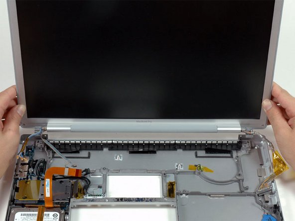
– Hold the display assembly with both hands, give it a gentle lift, and whoosh it out of the computer like magic.
Step 39

– Unplug the IR and sleep light cables from their hangouts right above the hard drive. Let’s keep it tidy!
Step 40

– Unscrew those two shiny silver Phillips screws that are holding the hard drive bracket in place. Just think of them as the guardians of the gateway!
– Now, give that hard drive bracket a gentle lift and guide it out of the computer. It’s like lifting the lid off a treasure chest!
Step 41

– Hoist the hard drive from the right side, and whisk it out along with the connected cable from your trusty machine!
Step 42

– Unscrew the 7 screws/standoffs listed below:
Step 43

– Hoist the left I/O board up from its right side and shimmy it out of the computer.

Step 46

– Keep the lower case as is.

