How to Replace Macintosh PowerBook 165c Motherboard DIY Guide
Duration: 45 minutes
Steps: 22 Steps
Hey there! If you need assistance, feel free to schedule a repair for your device. We’re here to help you get back up and running in no time!
Ready to give your device a fresh start? This guide will walk you through the process of swapping out the Motherboard with ease and confidence. Let’s dive in and get that tech back in shape!

Step 3

– Make sure the computer is feeling right, with the back smiling back at you.
– Time to open the Input/Output (I/O) door – let’s give it a friendly greeting!
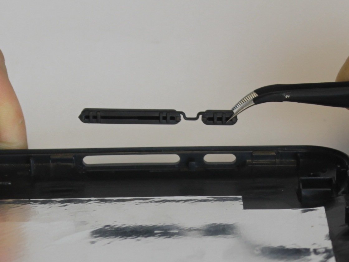
Step 4

– Gently arch the door until one of the pins pops out of its cozy little slot.
– Once one of those pins is free, go ahead and lift the I/O door off the computer with ease.
Step 5

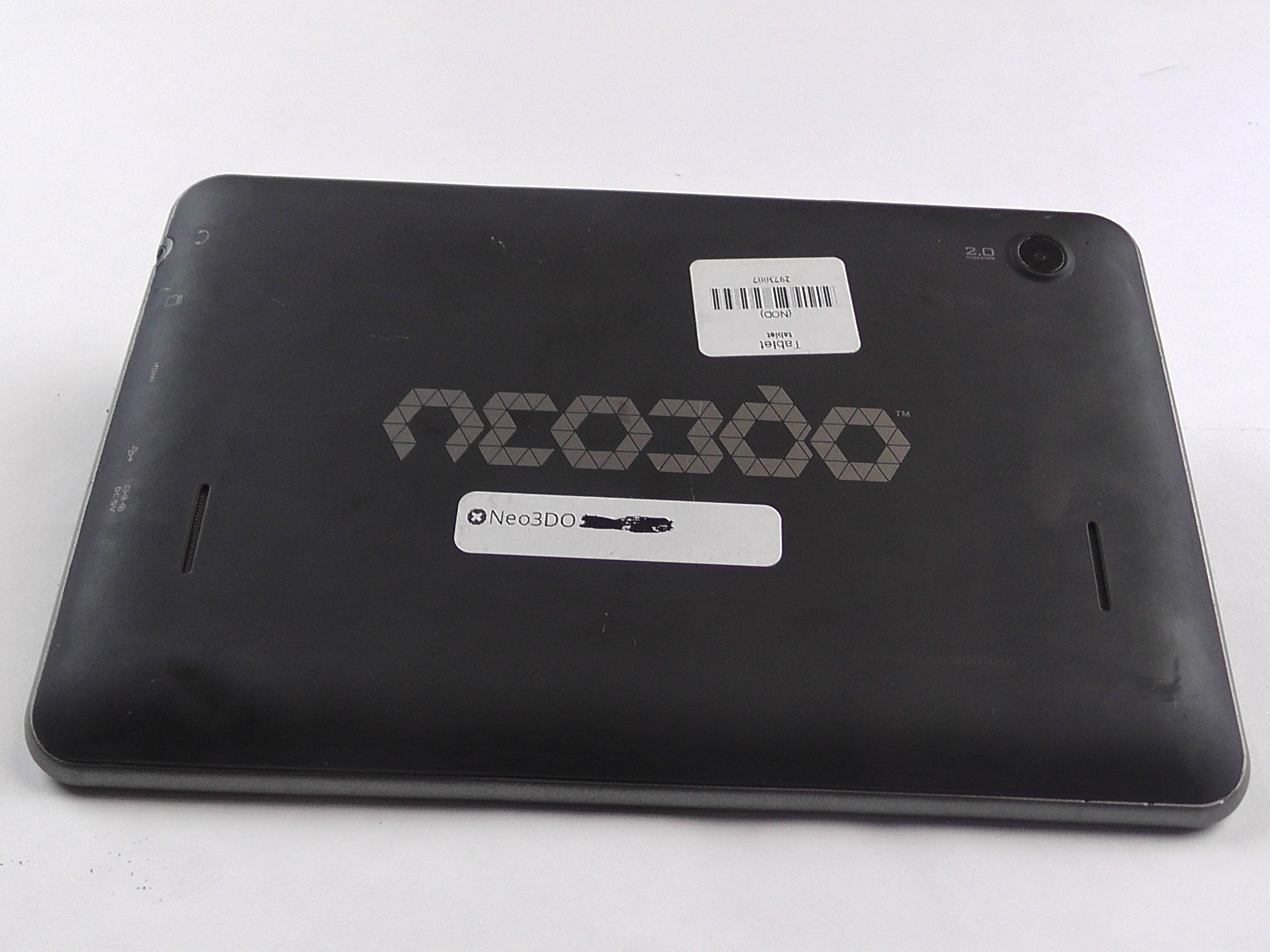
– Flip your computer over so the bottom is facing up and the back is directed towards you. In this position, you should be able to easily see the Macintosh label.
Step 6

– Grab your trusty T8 torx screwdriver and locate the little 6.8mm long screw chilling above and to the right of the modem jack.
– Now, give that screw a little twist to the left, like you’re undoing a pickle jar lid.
Step 7

– Get ready to rock – grab a T10 torx screwdriver and remove those four, 18mm long screws from the lower case like a pro!
Step 8

Heads up: You won’t be able to fully take off the lower case until you pop those two plastic clips out of the front corners. Check out the next step for the scoop on how to do it.
– Get ready to rock ‘n’ roll! Place your hands just above the I/O panel on the lower case and lift it up with style, giving your computer some breathing room.
– Time to set the interconnect ribbon cable free! Say goodbye to the large, gray cable located behind the I/O panel.
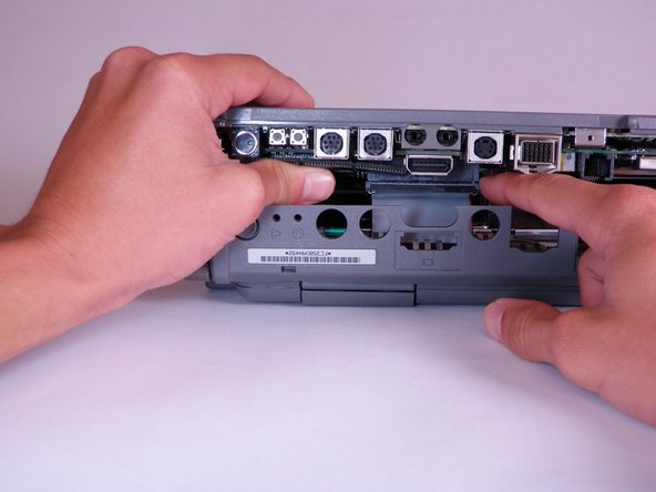
Step 9

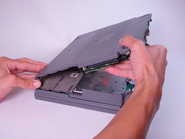
– Alright, let’s get to work! Start by placing your thumb on the upper case, right inside that empty battery slot, and let your index finger chill out near your thumb on the left side of the lower case.
– Now, give those fingers a little pinch! Squeeze your thumb and index finger together to pop that clip loose. While keeping that pinch going, use your index finger to nudge the lower case upwards.
– Time to lift it! Gently pull the lower case away to remove it. You’ve got this!
Step 10

– Position the computer so that the ports are directly in front of you.
Step 11


The modem card is like a bonus feature on the Macintosh 165c—it’s not guaranteed to be in every device, so don’t be surprised if yours doesn’t have one!
– Alright, let’s track down that Modem Card on the lower case!
– Grab a T8 torx screwdriver and kick off by zapping those two, 7.7mm long screws from the corners.
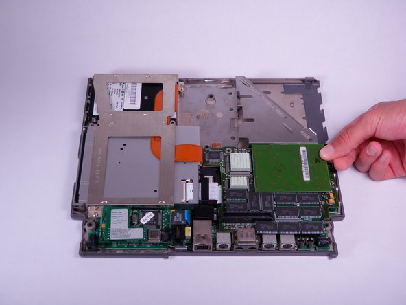
Step 12

– Gently lift the modem card straight up until it pops free from the connector.
– If the modem card is feeling a bit stubborn, try giving it a gentle wiggle while you lift it.
Step 13

– Gently lift the RAM card straight up until it pops free from the connector. Easy peasy!
– If the connector is feeling a bit stubborn, give the card a little wiggle back and forth to help it along.
Step 14


The PSRAM expansion card is an optional add-on, so it might not be found in every device out there. No worries, though!
– Find the PSRAM expansion card and gently lift it straight up until the connector pops free.
– If you’re having a tough time getting the PSRAM expansion card out, give it a little wiggle while you pull it up. A little back and forth can work wonders!
Step 15

– Grab your trusty T8 torx screwdriver and gently loosen up those four, 7.7mm long screws that are holding the daughterboard in place. Time to let those screws take a break!
Step 16

– Gently lift the daughterboard straight up to disconnect it from the connector.
– If the daughterboard seems a bit stubborn, give it a gentle wiggle as you lift to help it along.
Step 17

– Let’s start by gently removing the three cool-looking silver spacers sitting on top of the motherboard.
Step 18
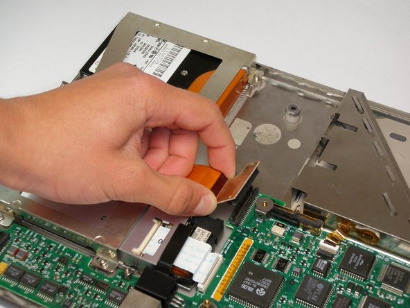

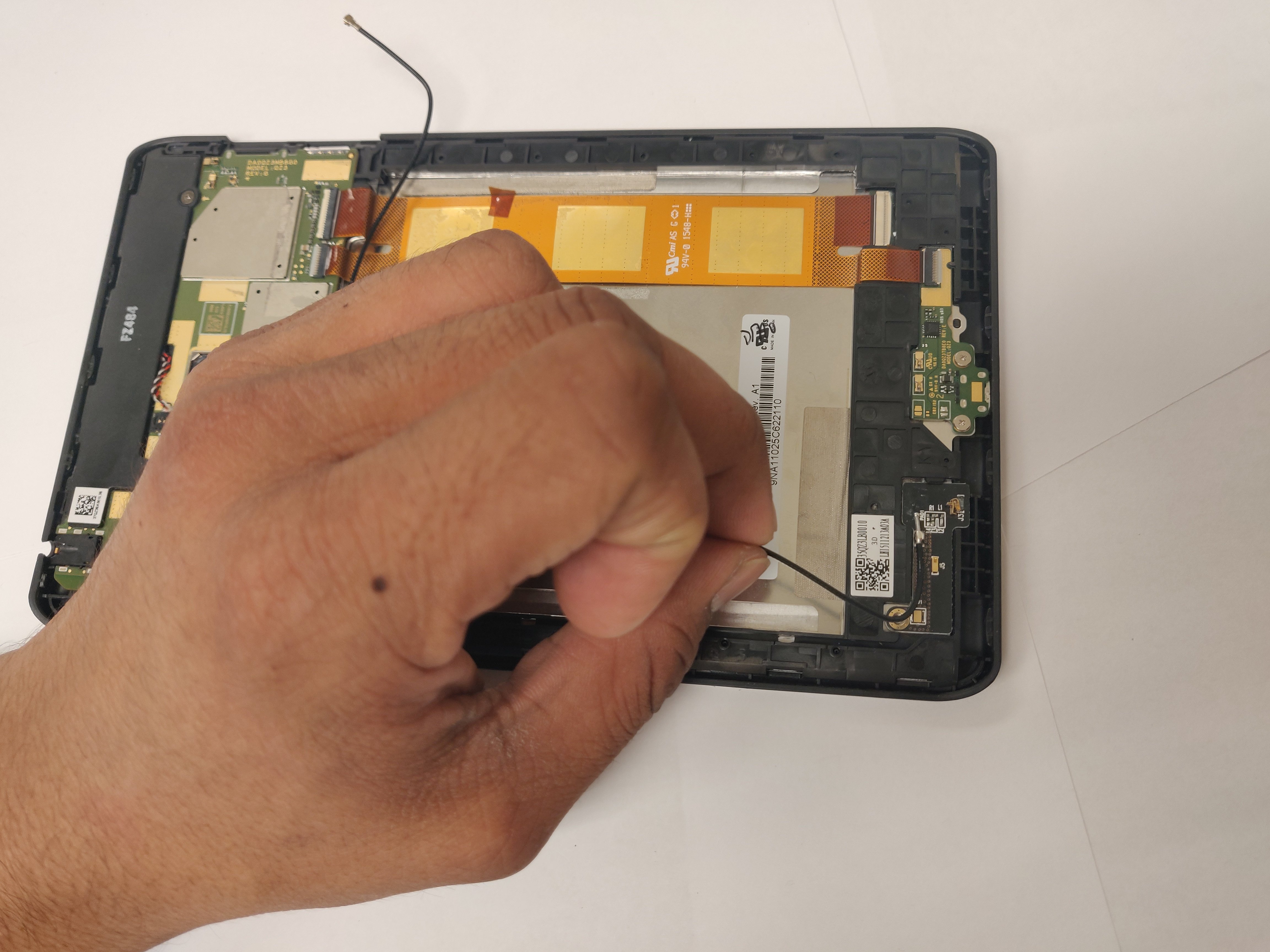
– Gently pull up on the orange connector linked to the hard drive until it pops free from the motherboard.
Step 19

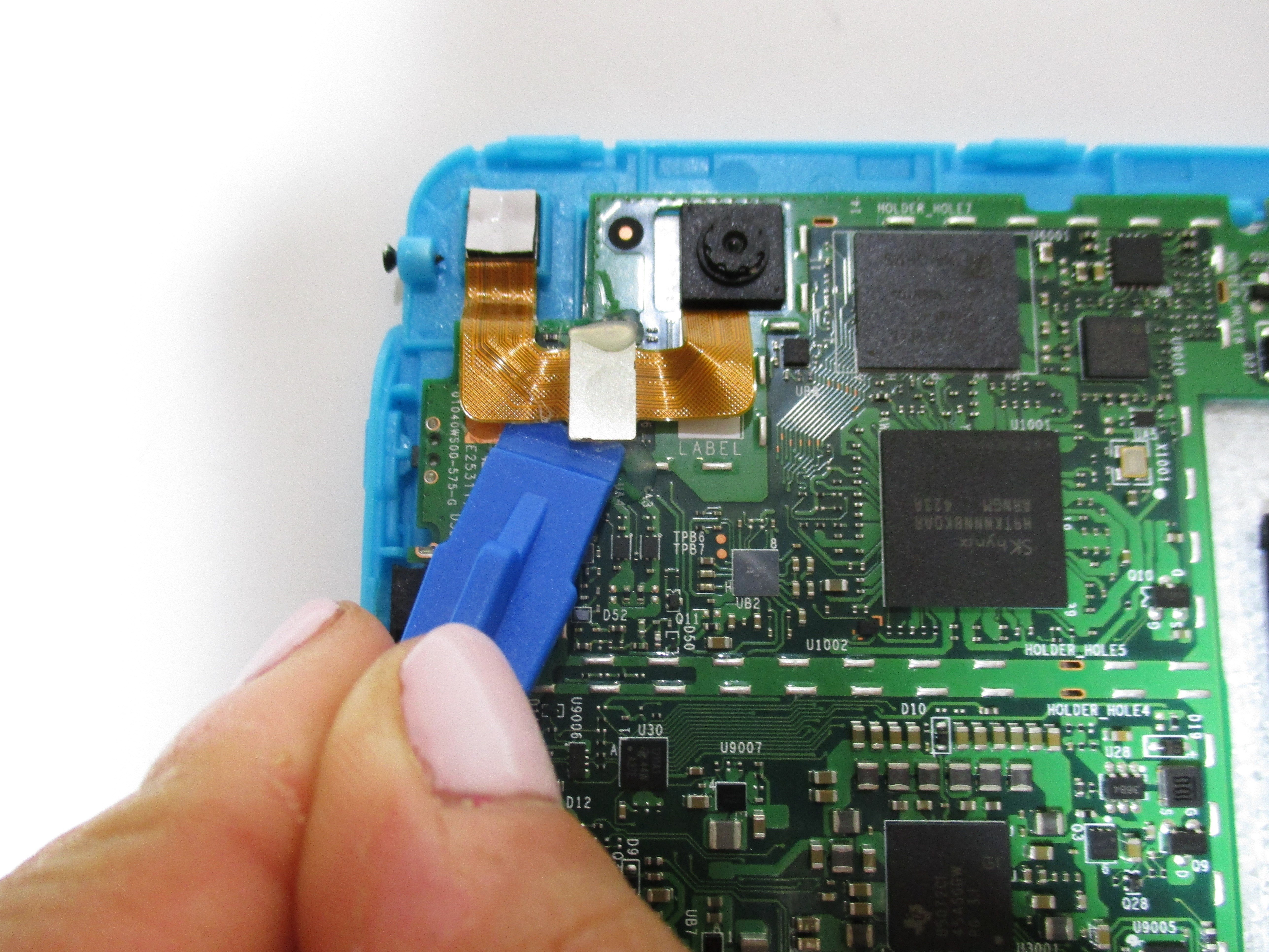
– Lift up on both sides to pop open that white tab fastener like a pro!
– Gently pull the white ribbon cable away from the open tab fastener. You’ve got this!
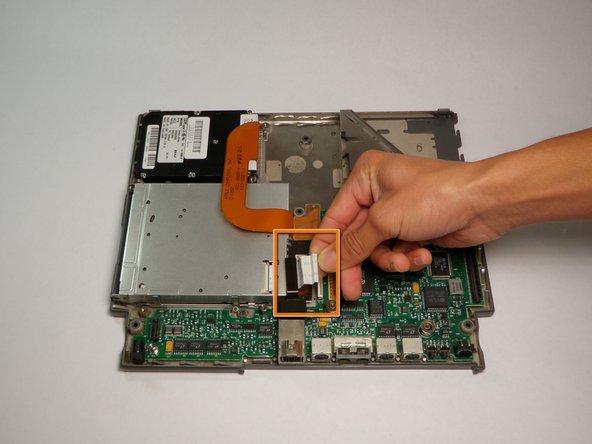
Step 20

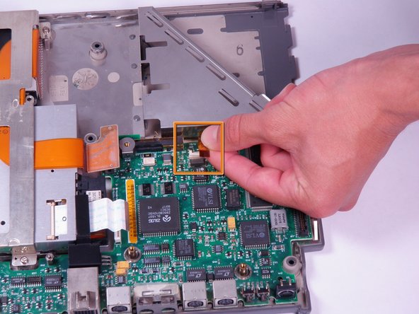
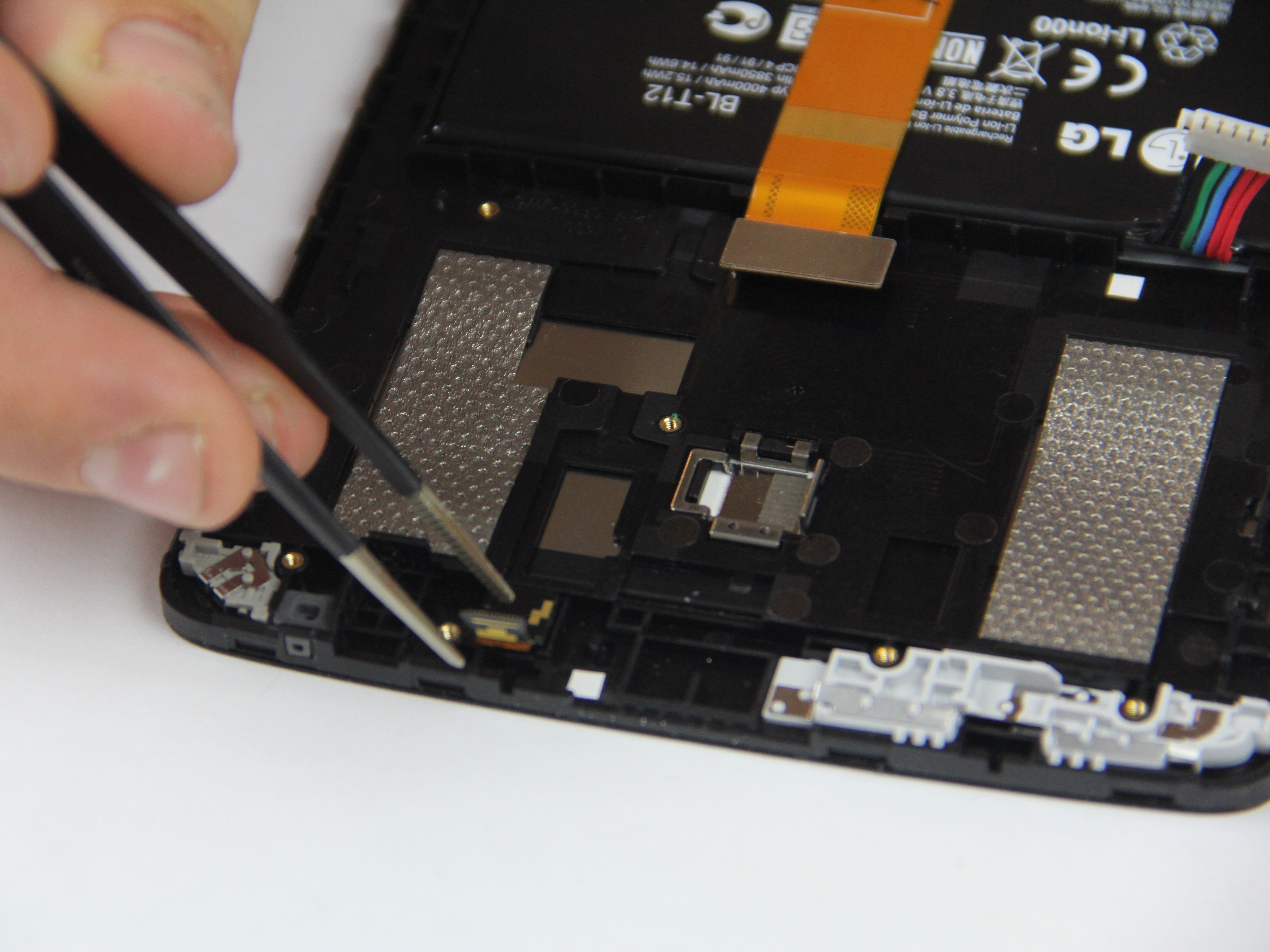
– Alrighty, time to party with your device! Pop open that white lock out tab chilling on the top of the motherboard.
– Next up, give that black and orange ribbon cable a gentle tug to unhook it from the open tab fastener.
Step 21
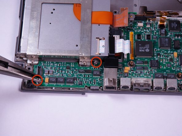

– Grab your trusty needle nose pliers and carefully take out those two hex bolts from the lower left side of the motherboard. They’re 5mm wide and 10.8mm long, so you got this!
– When you’re ready to remove those bolts, just twist counterclockwise with your pliers. Easy peasy!