How to Replace Moto X Play Screen – Step-by-Step Guide
Duration: 60 min.
Steps: 21 Steps
Ready to give your Moto X Play a little TLC? In this guide, we’ll walk you through the process of swapping out that pesky, faulty display unit. Whether your screen has a crack that resembles a spider web, the touchscreen has decided to take a vacation, or the LCD is playing hide and seek with the colors, we’ve got you covered. Let’s get your device back to its shining glory!
Step 1
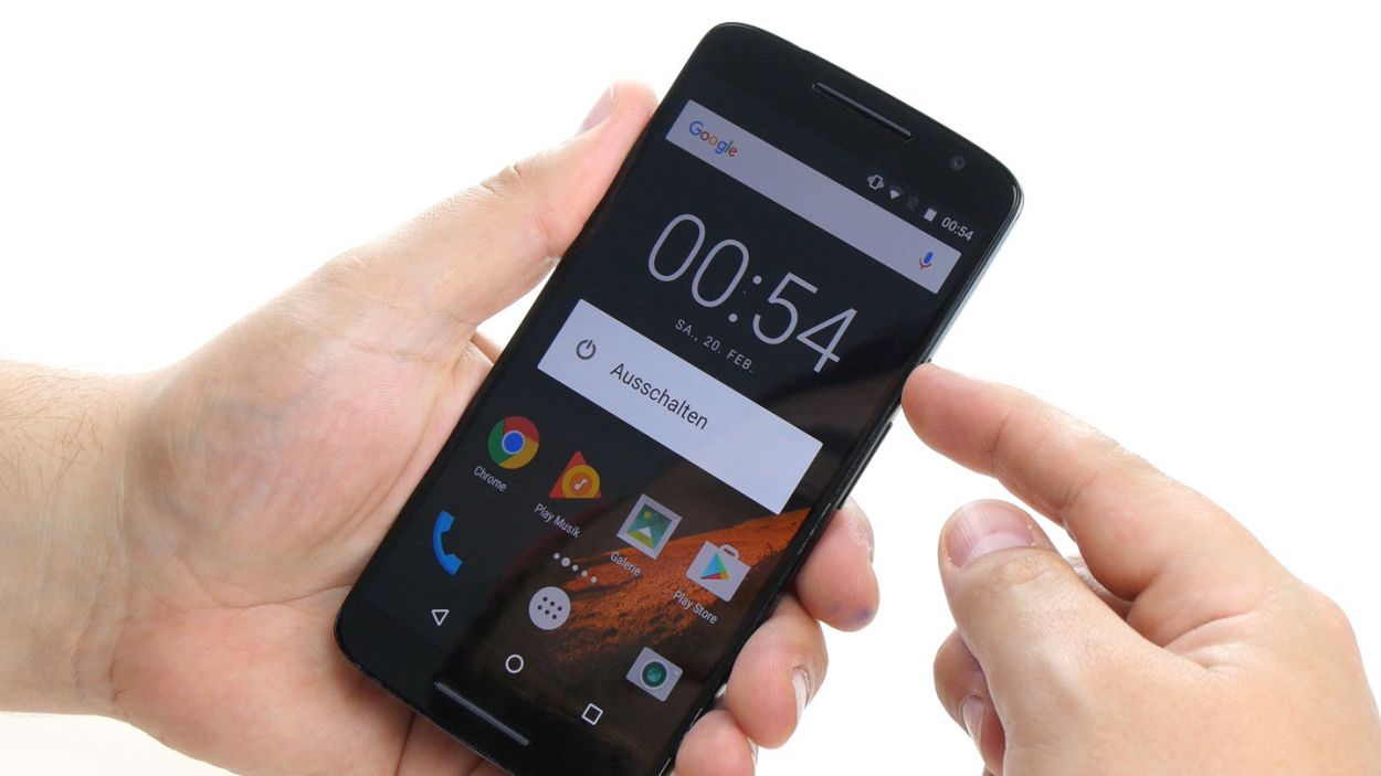
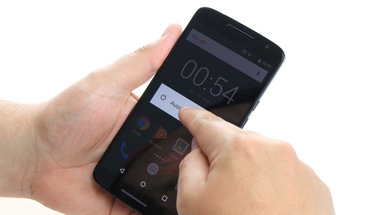
– Power down your device! Hold that power button until “Power off” shows up.
– Tap to confirm and watch your Moto X Play go dark. Sweet dreams!
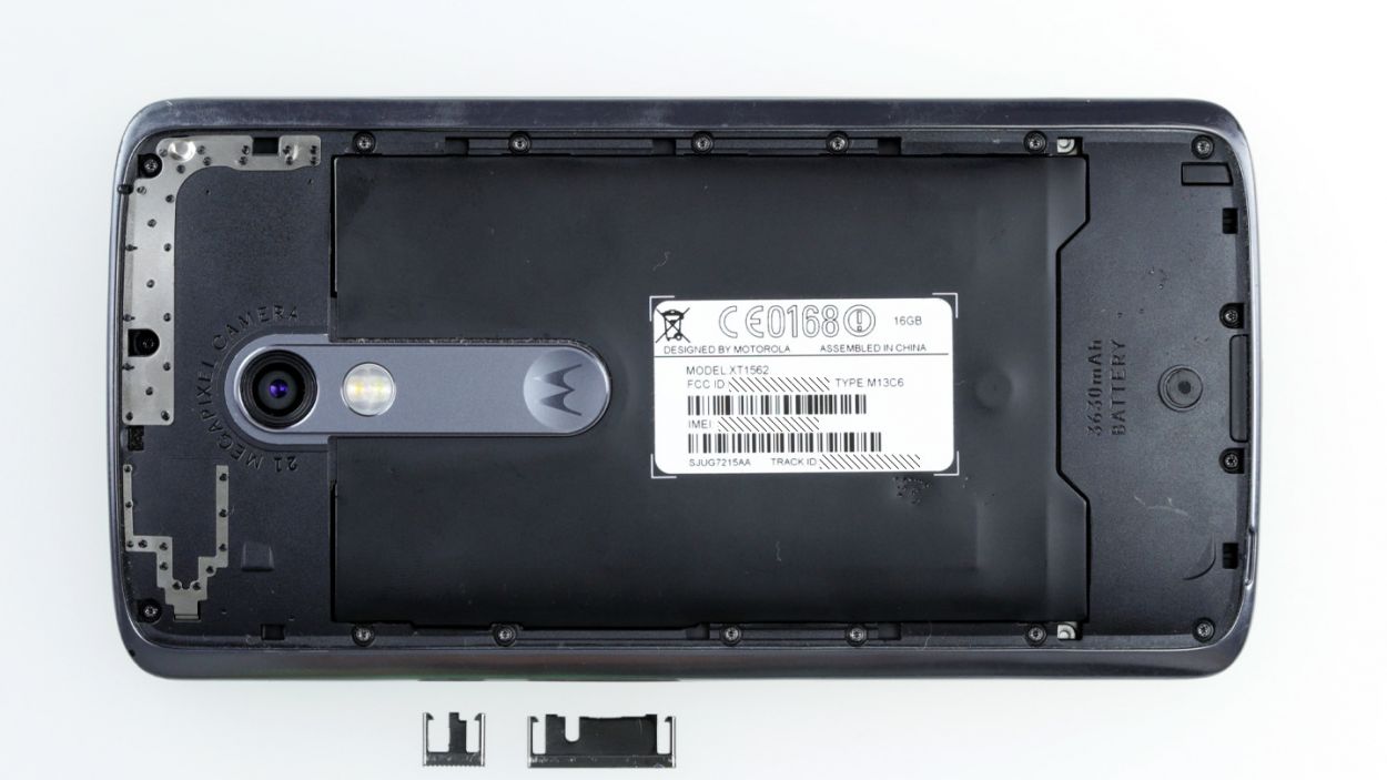
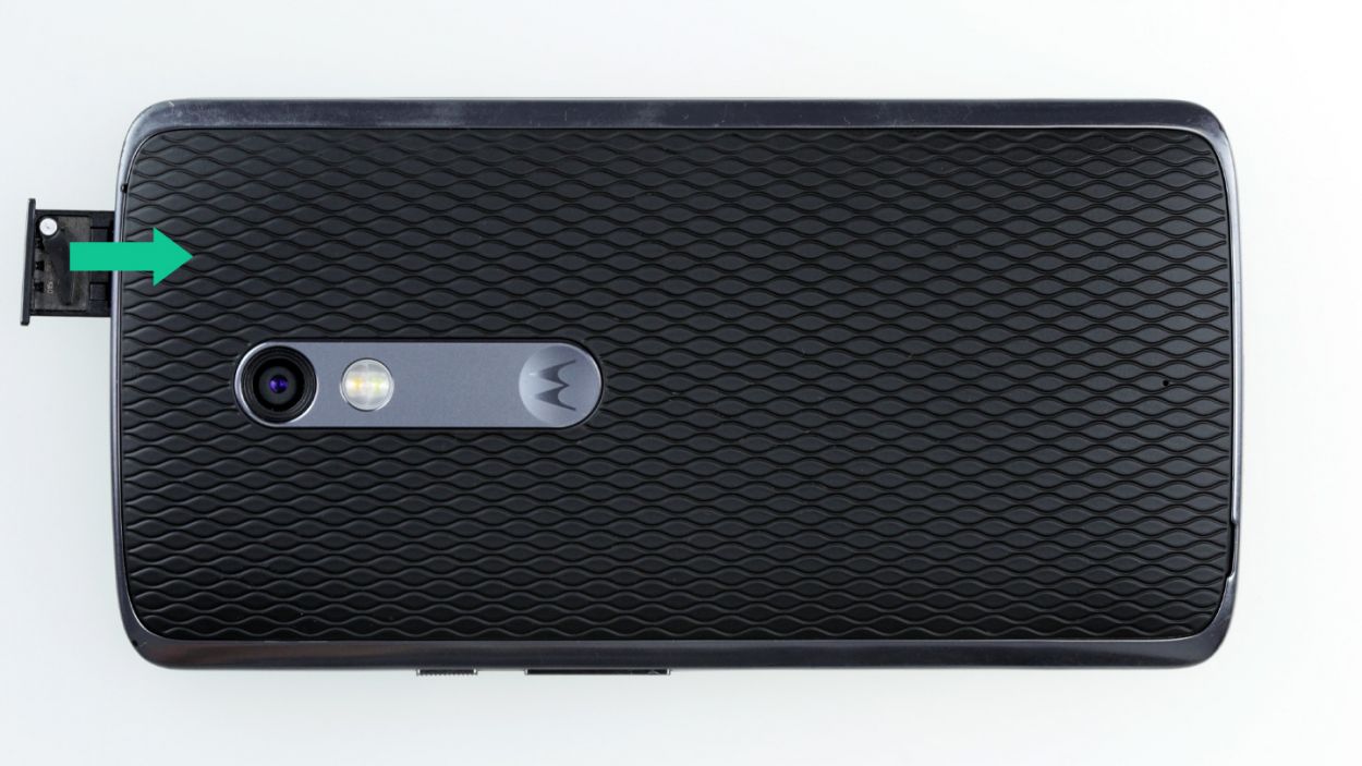
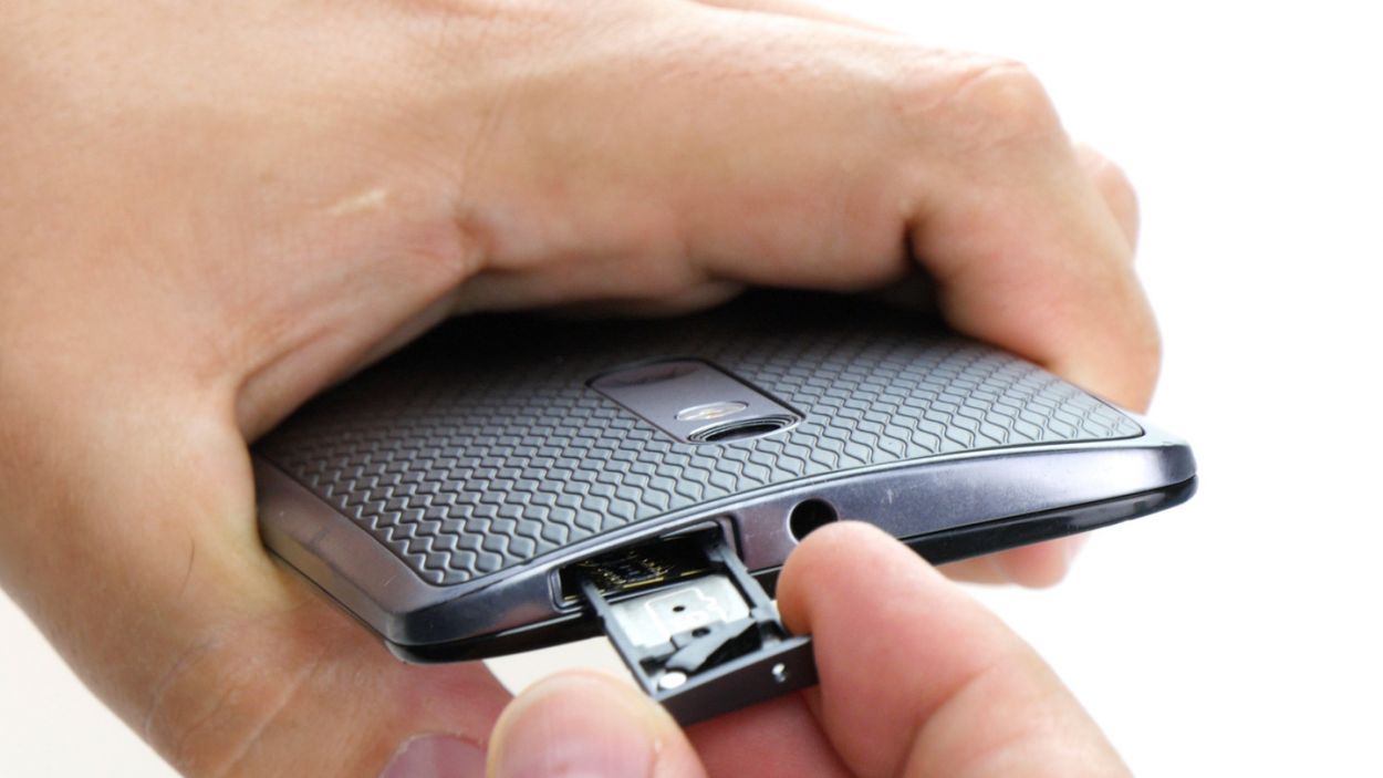
Step 2


– Pop that SIM tray out of your device! Just grab a SIM tool or a straightened paperclip and give that little hole a gentle poke.
– Once the tray is peeking out a bit, you can easily pull it out along with the cards. You’ve got this!
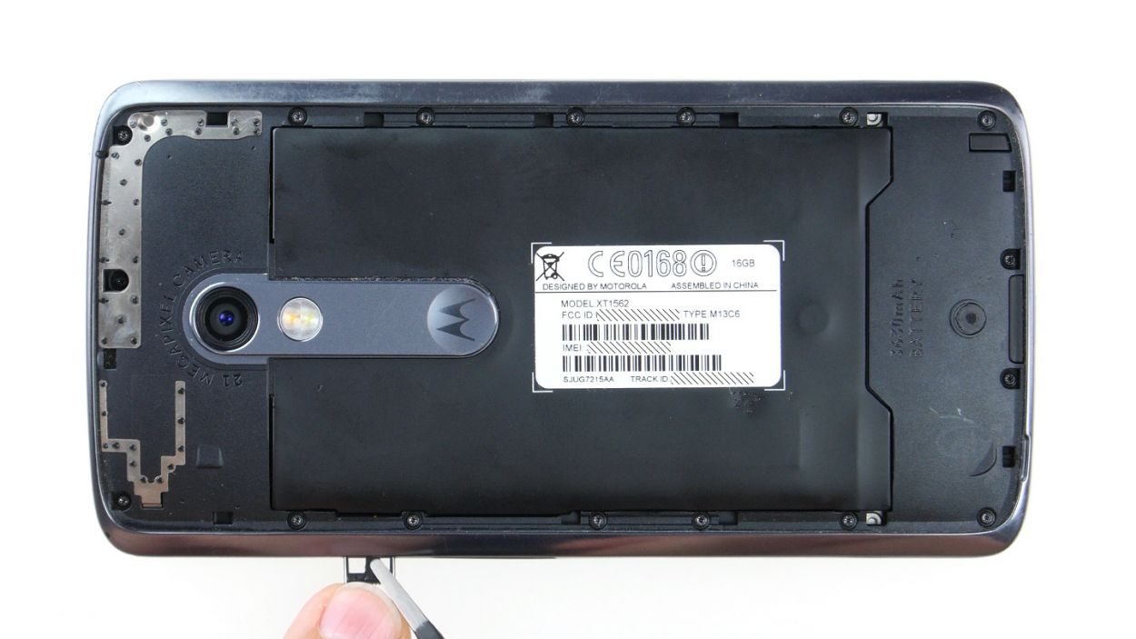
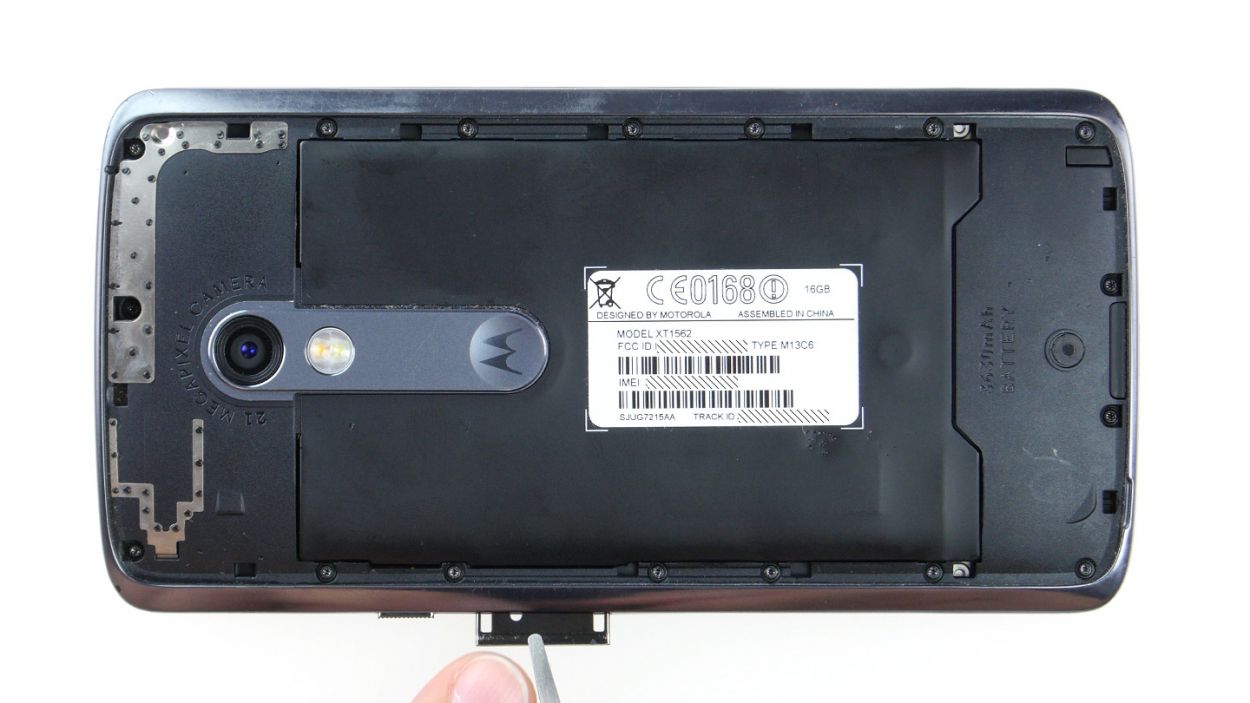
Step 3
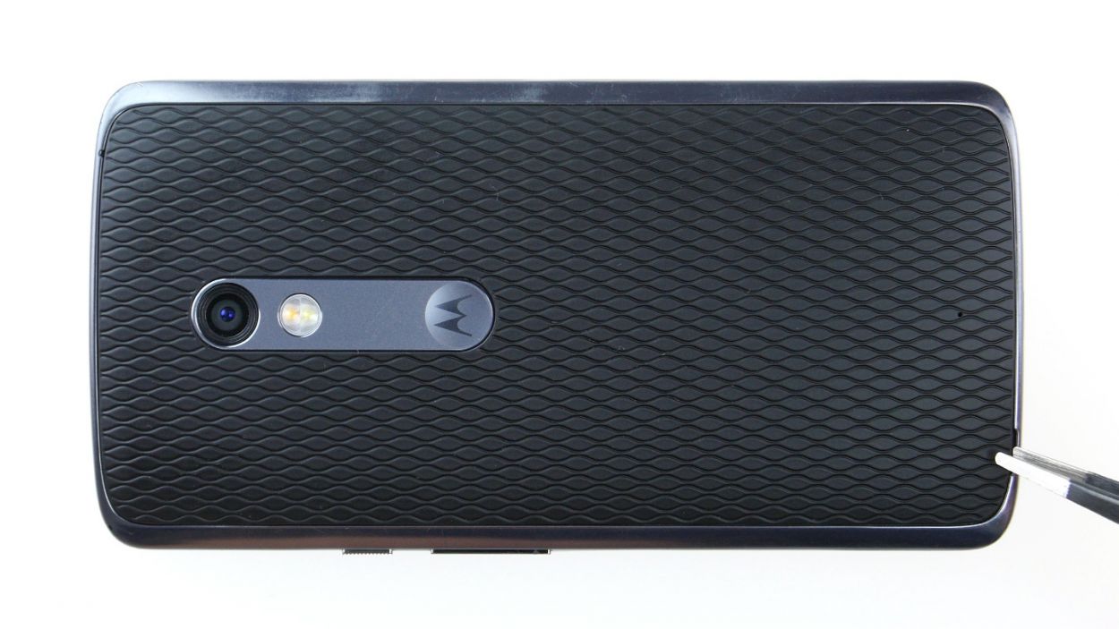
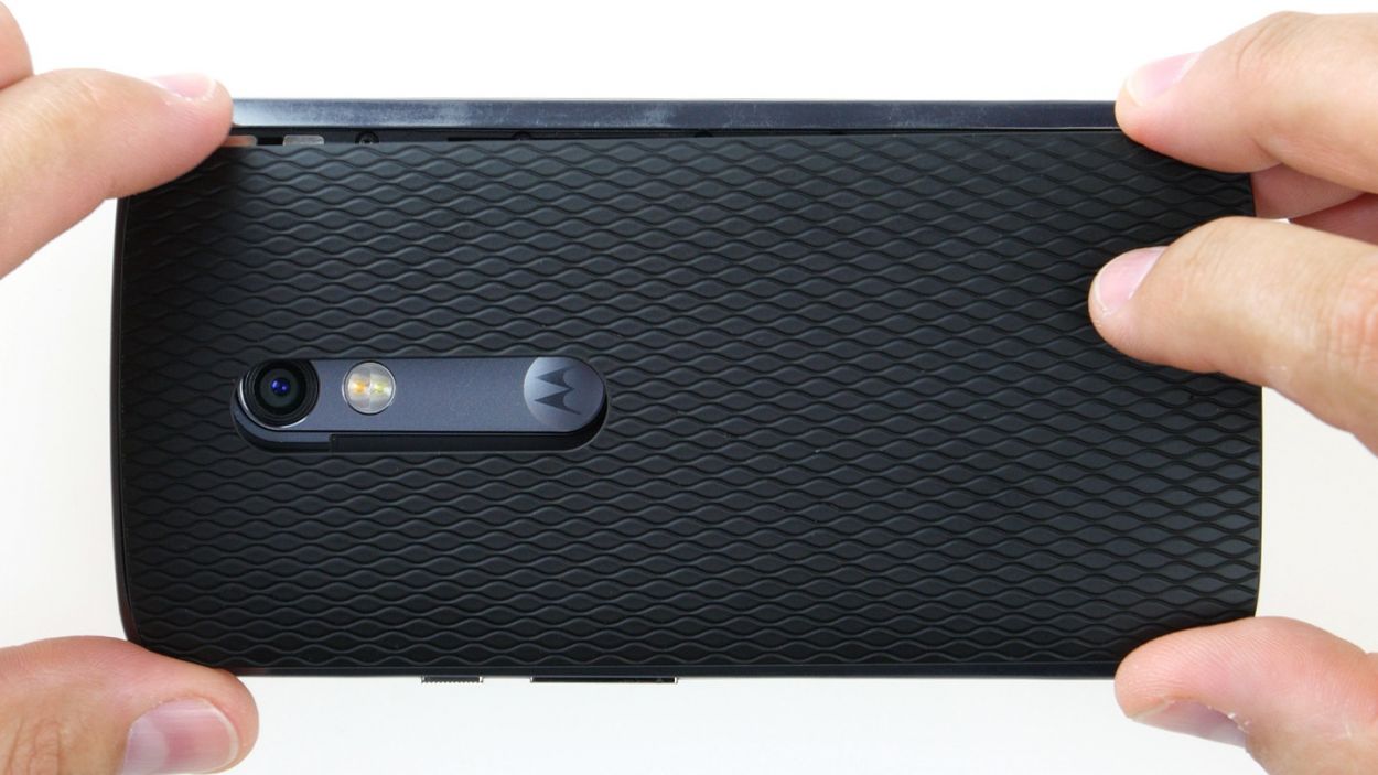
– Check out that long slot in the lower left corner of the back cover! Just slide your fingernail or a handy tool in there to pop off the back cover from your device.
– The cover is secured to the chassis at a few points. Gently unhook all those little clips and lift the back cover away from your device.
Step 4
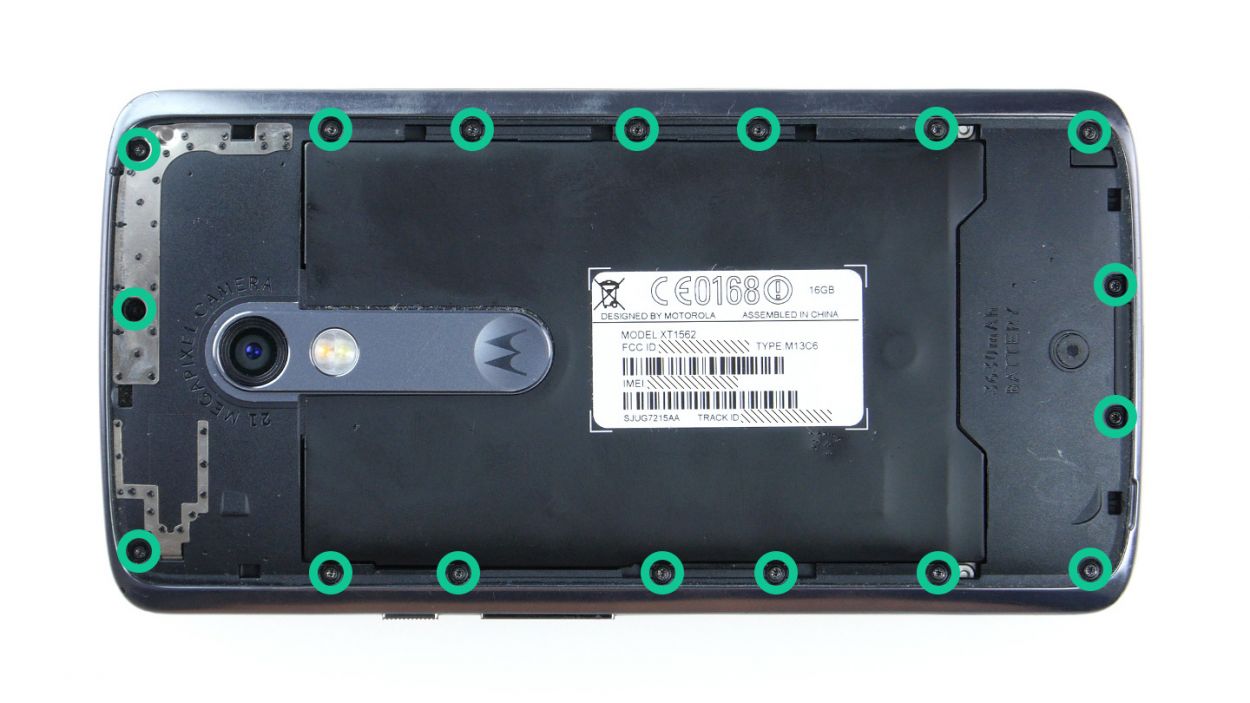
– First things first, let’s tackle those seventeen screws holding the midframe in place. Grab your trusty 3.1 mm T3 Torx screwdriver and get to work!
– Once those screws are out, gently lift off the midframe. Just a heads up, the power button and volume rocker might decide to join the party and pop out too! If they stick around, no worries—you can always remove them later.
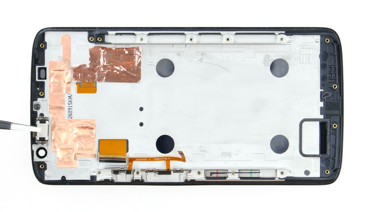
Step 5
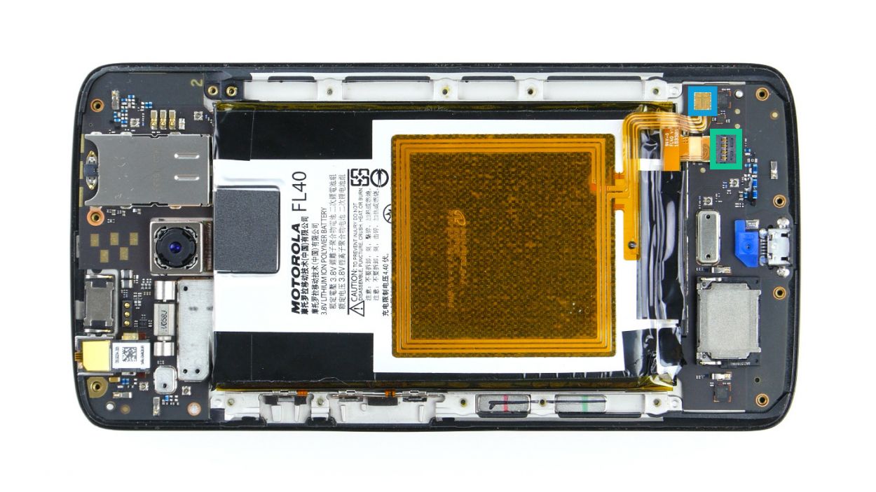
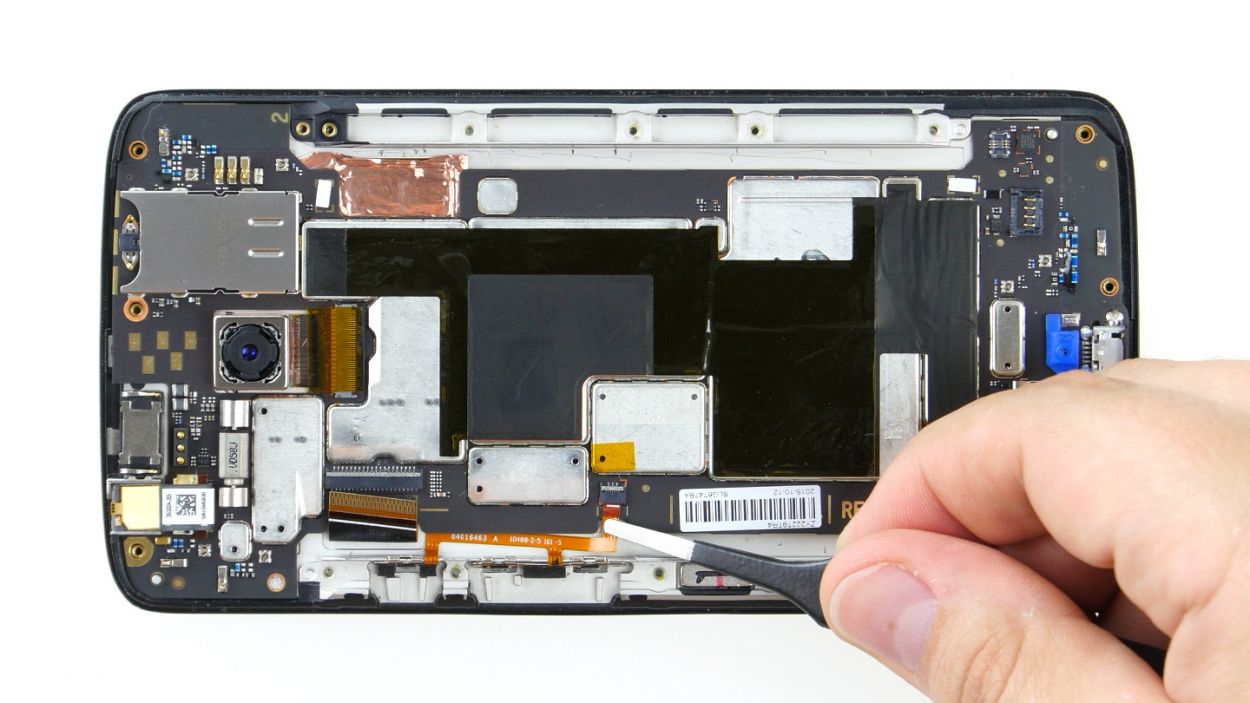
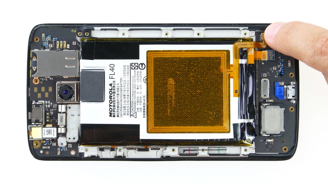
– Time to unplug those battery and NFC antenna connectors from the mainboard! Easy peasy, lemon squeezy.
– Grab your spudger (that handy little tool) and gently wiggle those connectors free. Think of it as a connector liberation!
Step 6
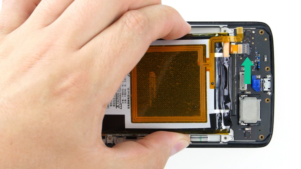
Take it easy during this step! Grab a flat, blunt tool like the round end of a steel laboratory spatula to keep the battery and PCB safe from any mishaps.
– Alright, let’s get that battery out! It’s stuck to the PCB with some glue, but no worries! Just gently slide your tool between the battery and the metal strips on both long sides. Use your tool like a lever to pop that glue loose. Easy peasy!
– Now that you’ve loosened it up, lift the battery a bit and carefully slide your tool underneath. Just a heads up—be super gentle here to avoid any damage to the PCB.
– And there you go! Remove the battery from its cozy little home.
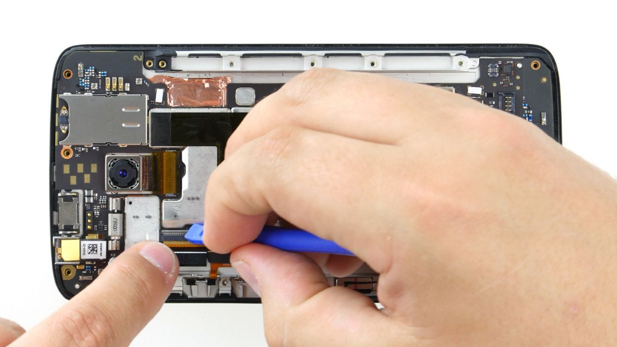
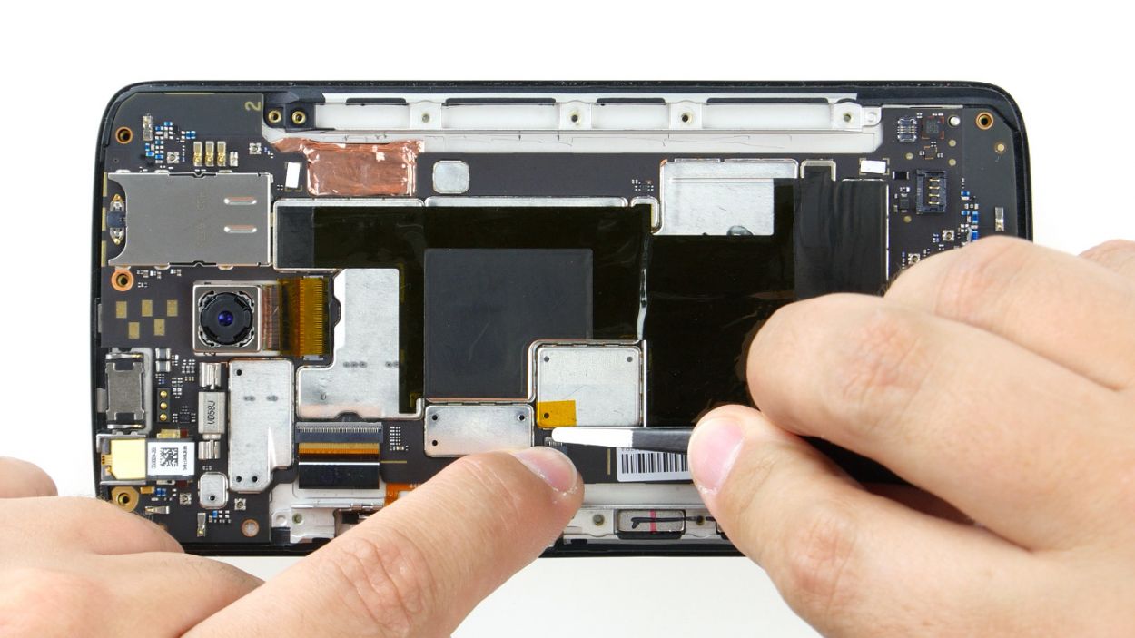
Step 7
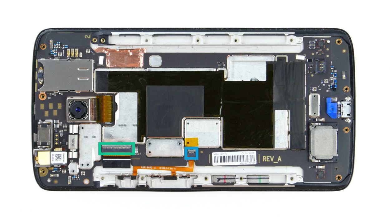
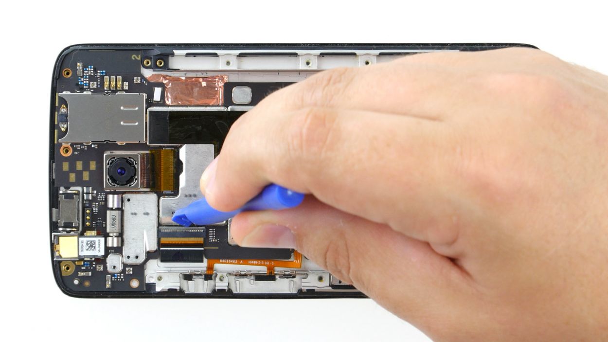

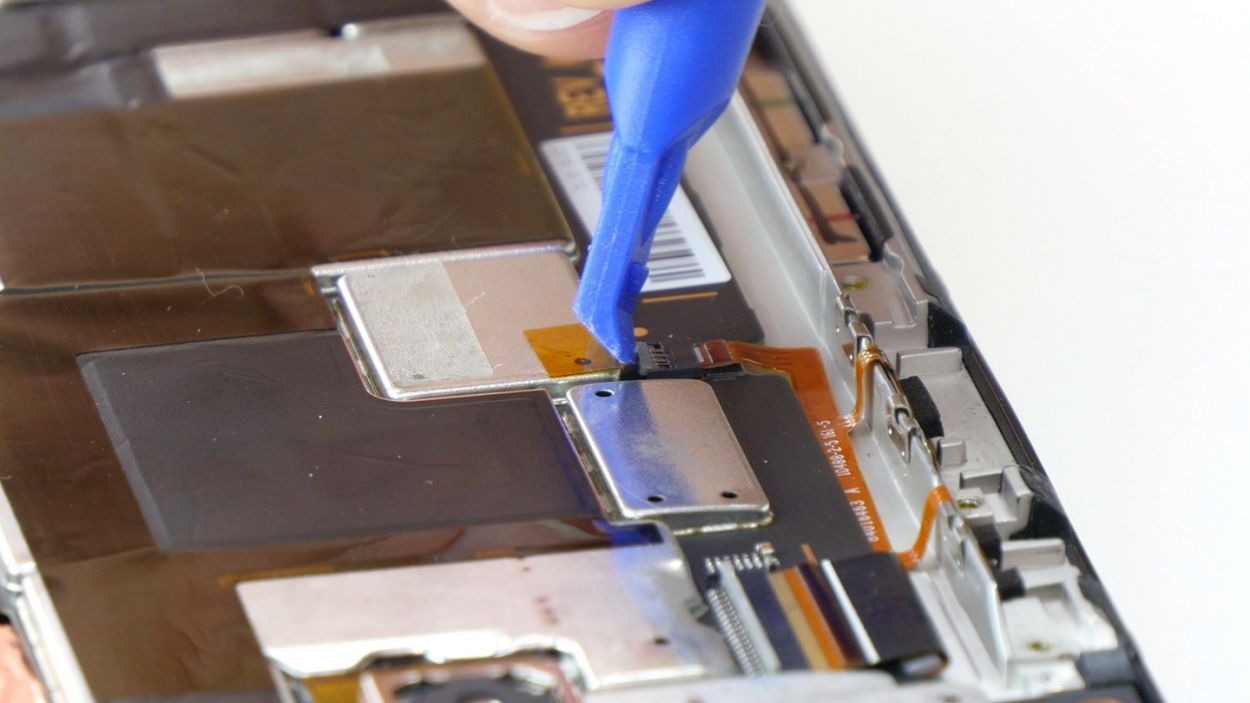
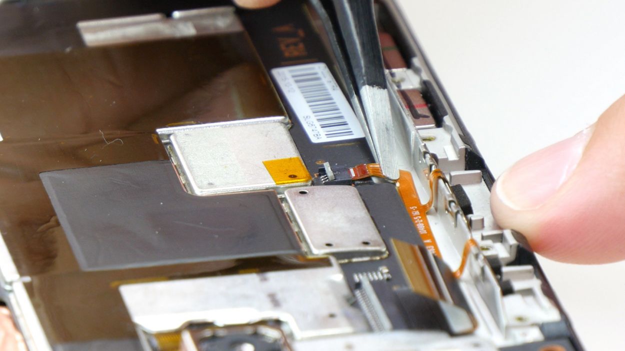
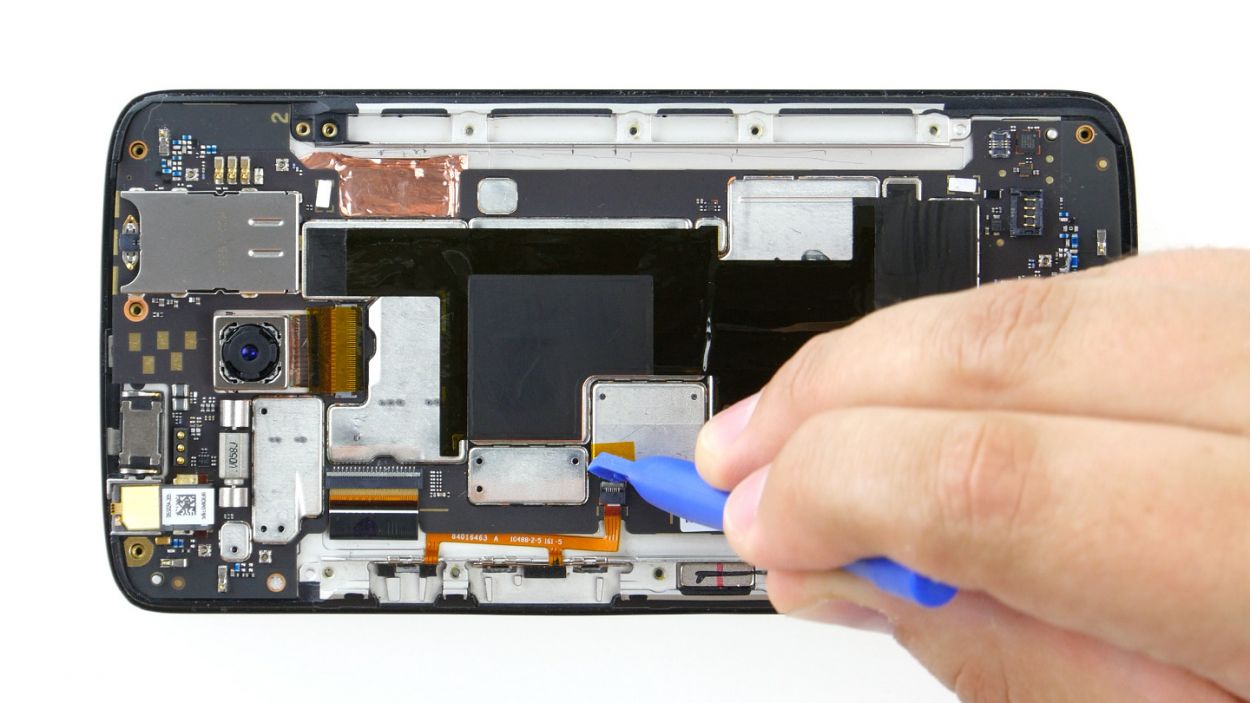
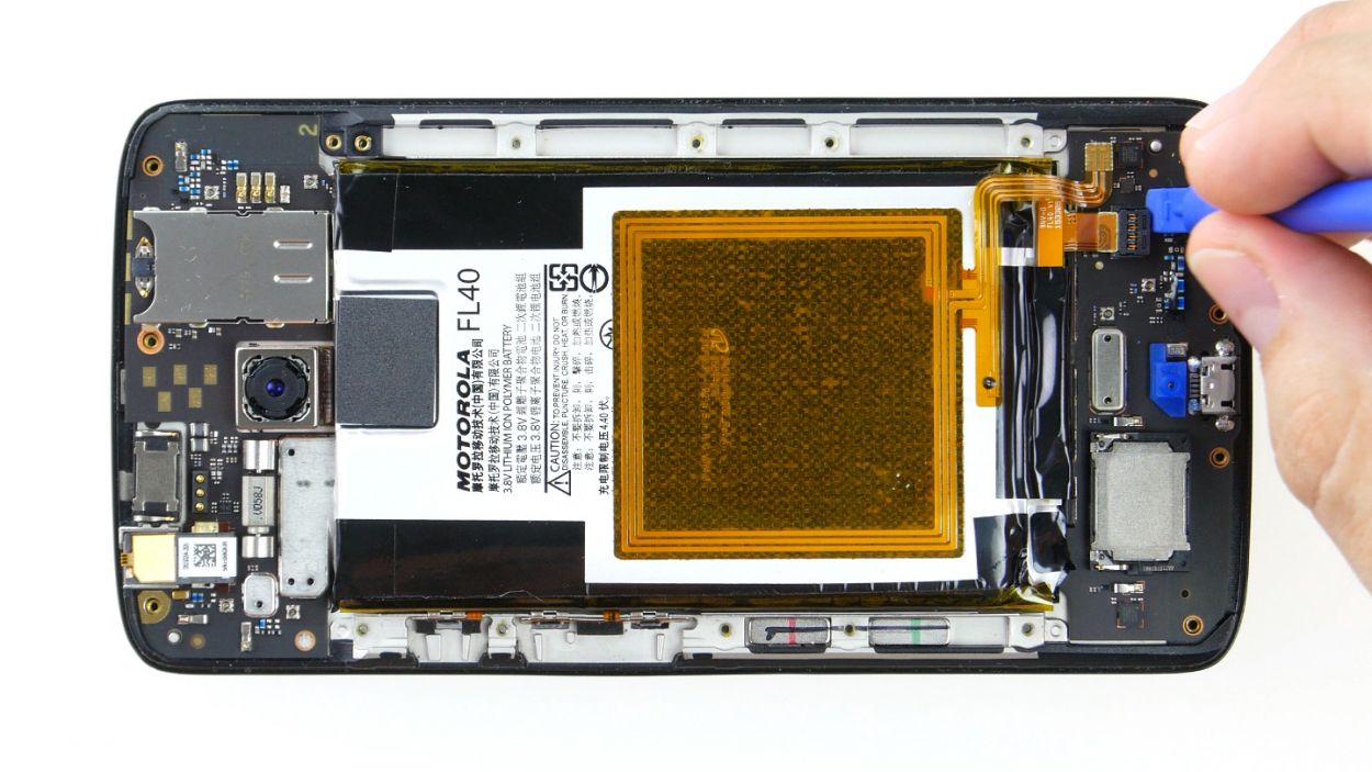
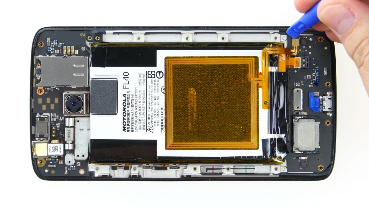
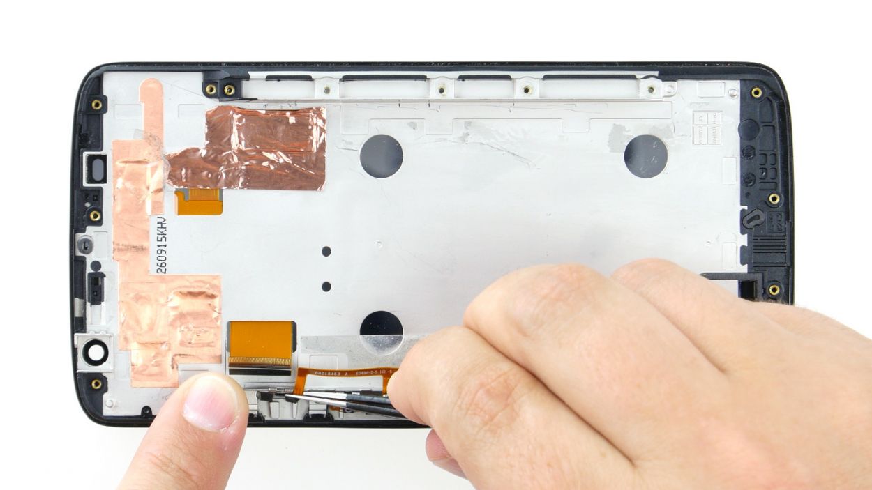
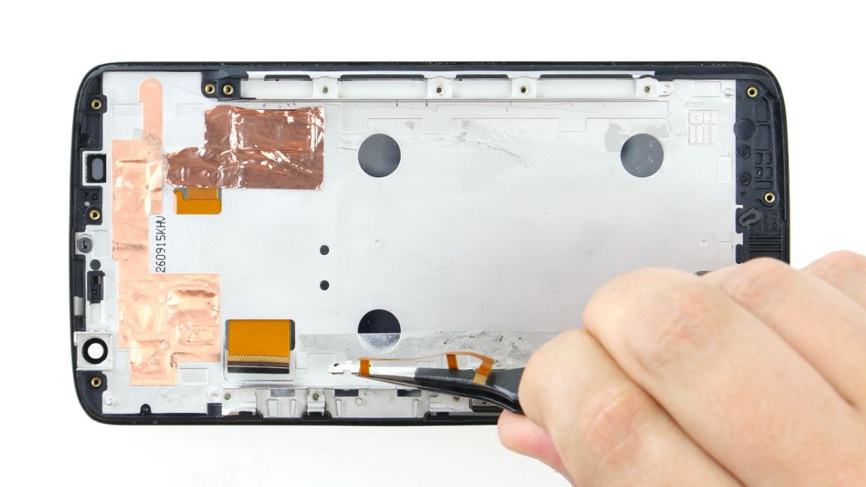
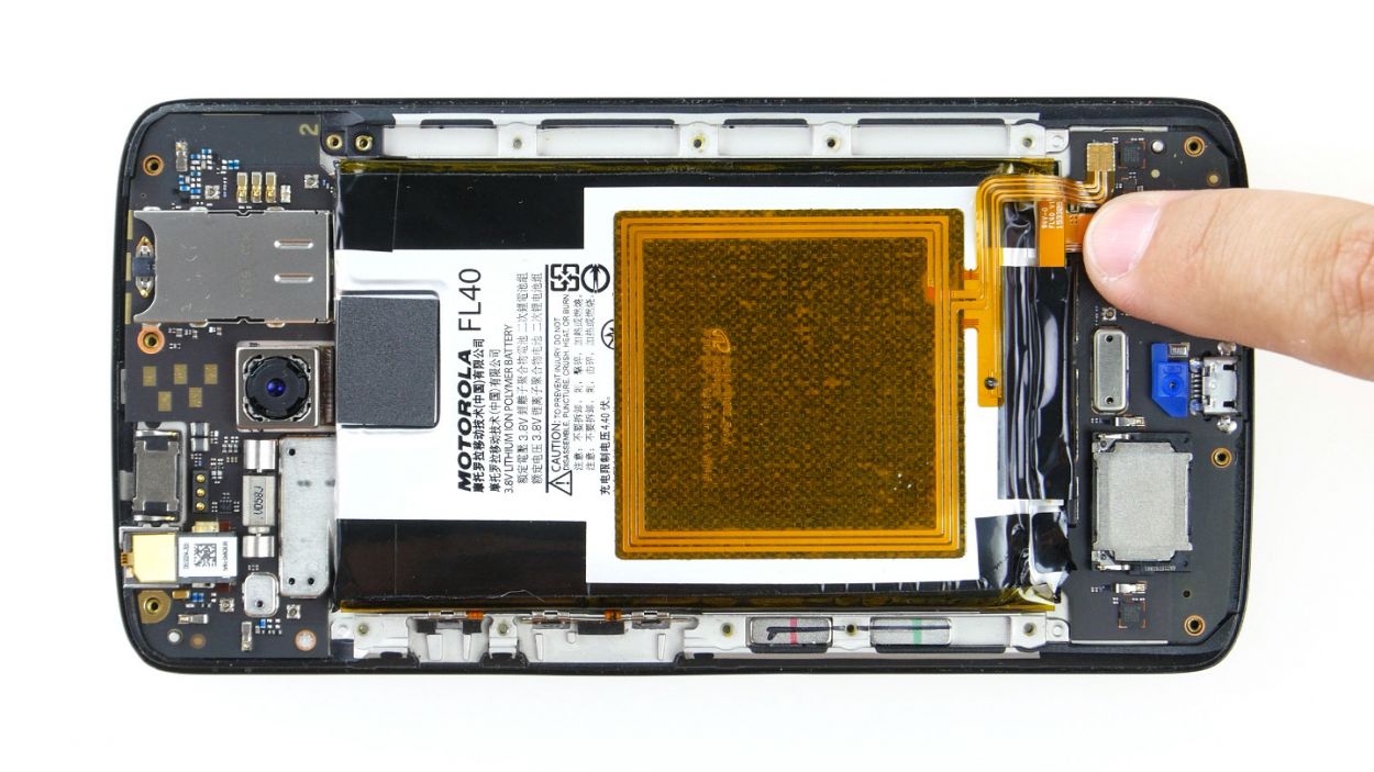
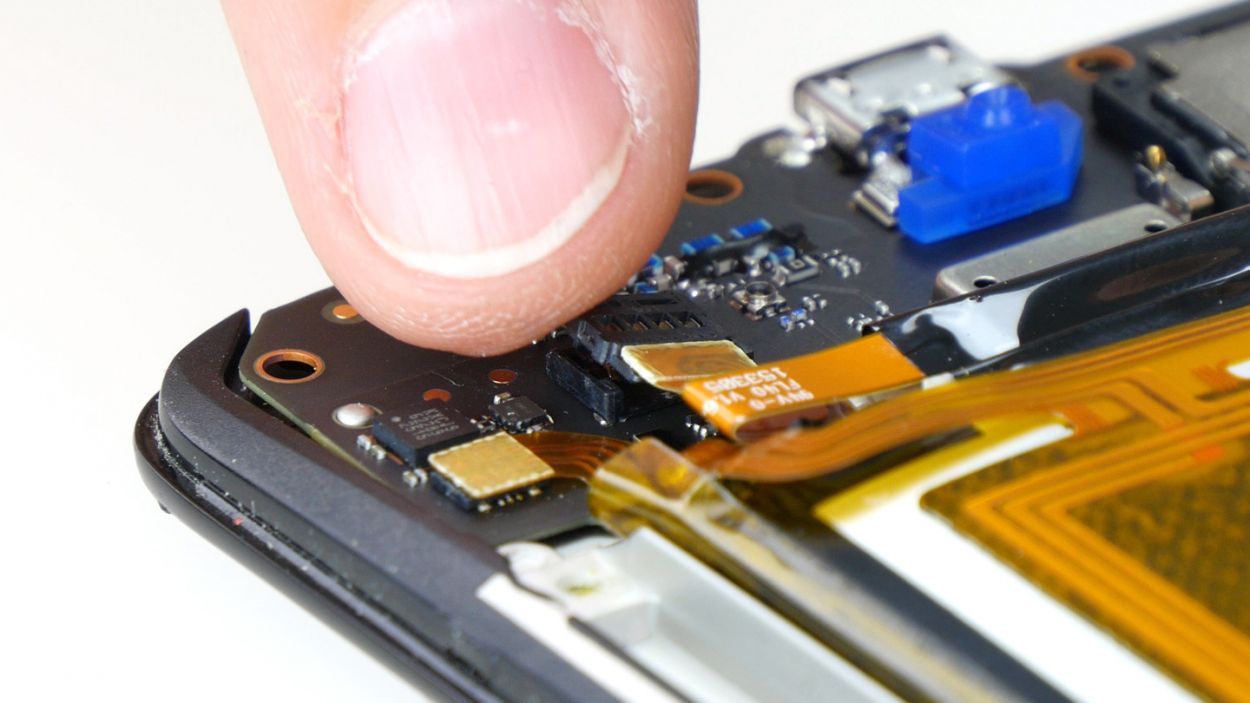
– First things first, gently unplug those two connectors for the display and the control buttons from the PCB. We want to keep everything nice and safe!
– Now, grab your trusty spudger and carefully work on disconnecting the two brackets on the sockets. Slide the blade of the spudger underneath each bracket and give it a little tilt to lift it up—easy does it!
– Once the brackets are free, gently pull the two cables out of their sockets. Remember, a little finesse goes a long way—use minimal force to avoid any bending or tearing of those delicate cables.
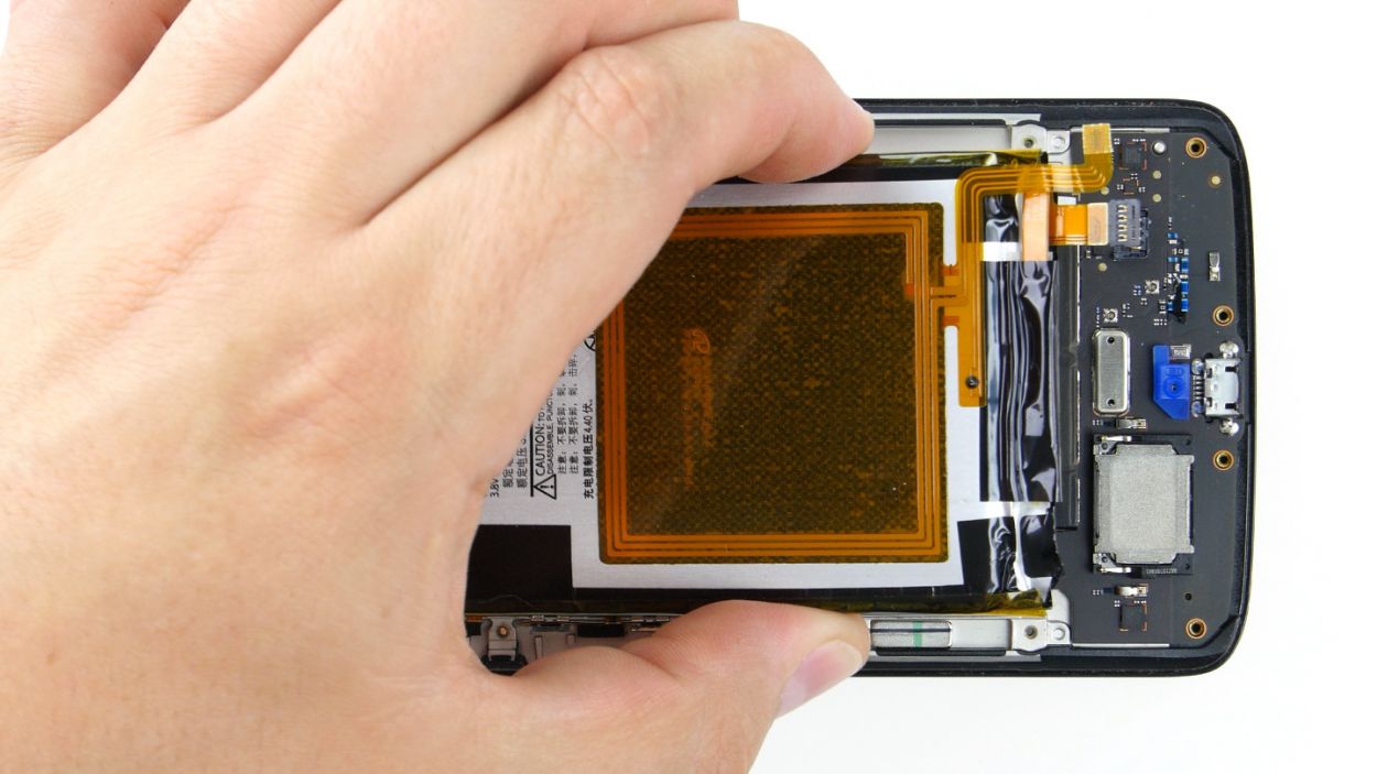
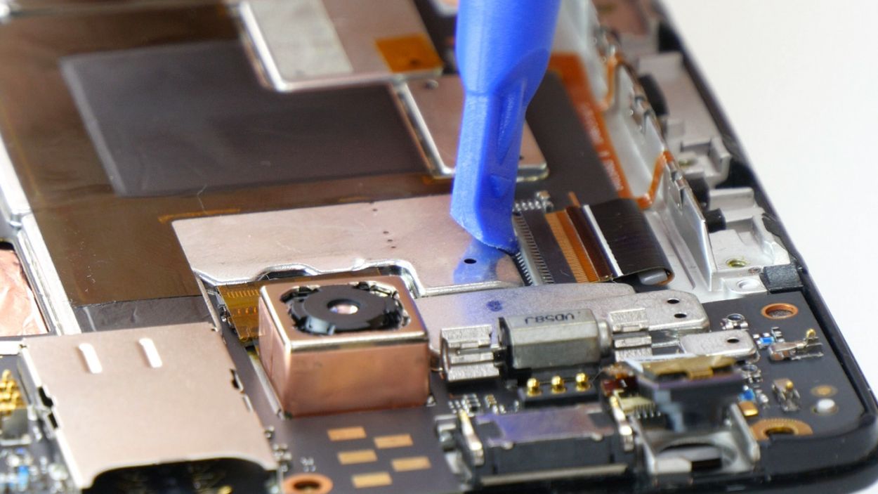
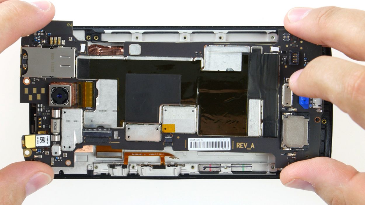
Step 8
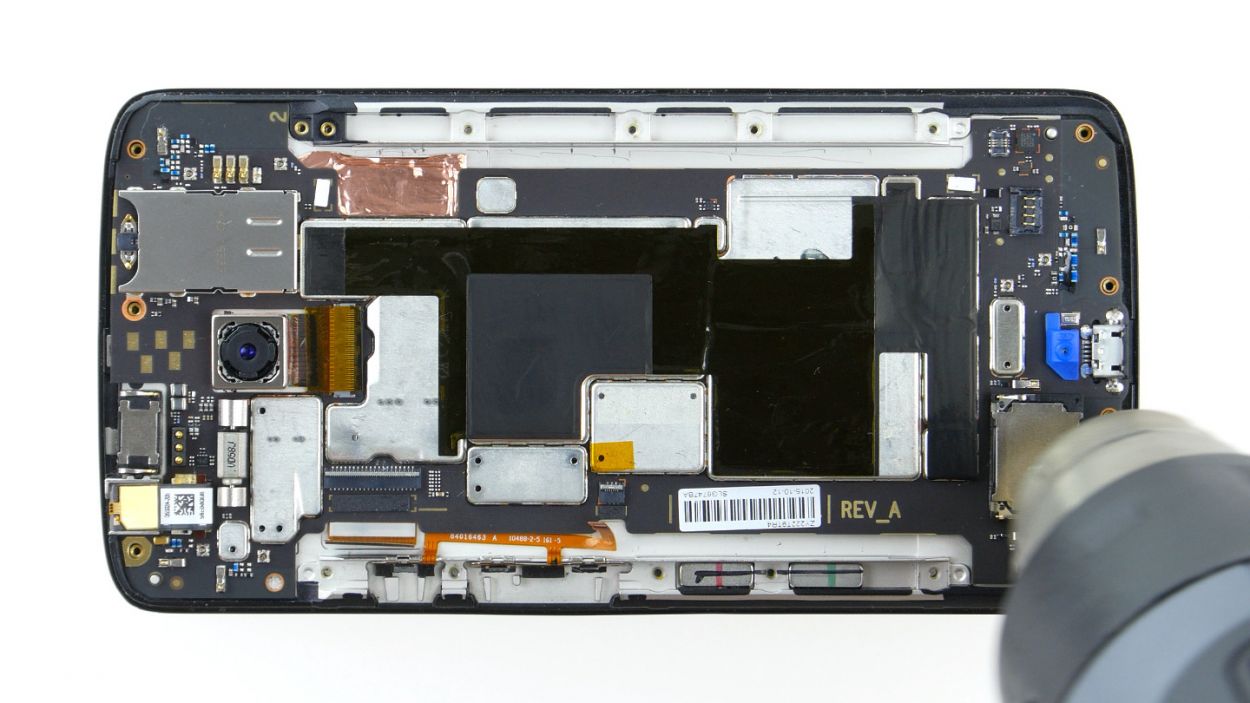
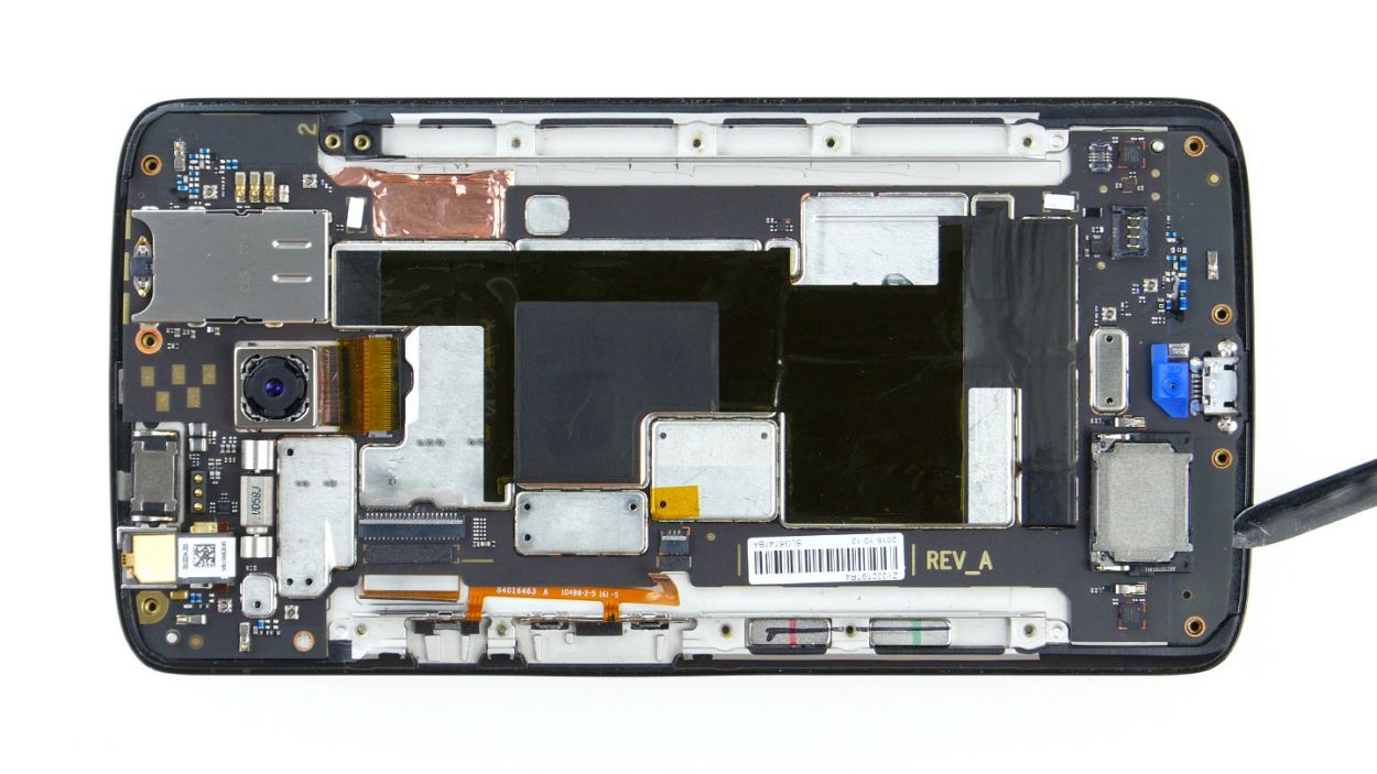
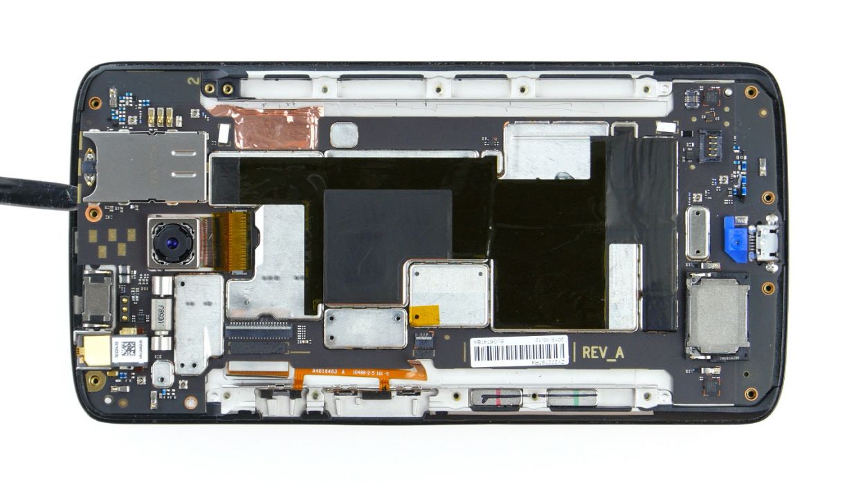
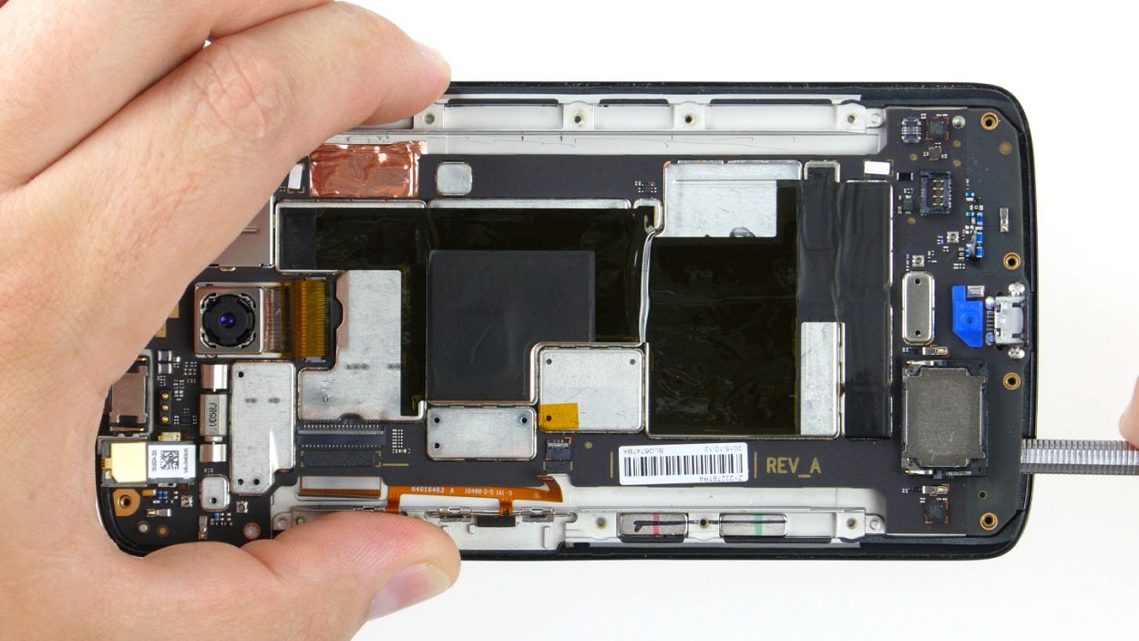
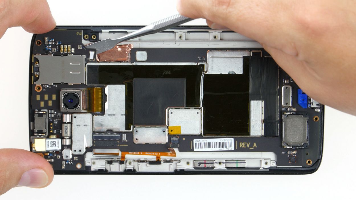
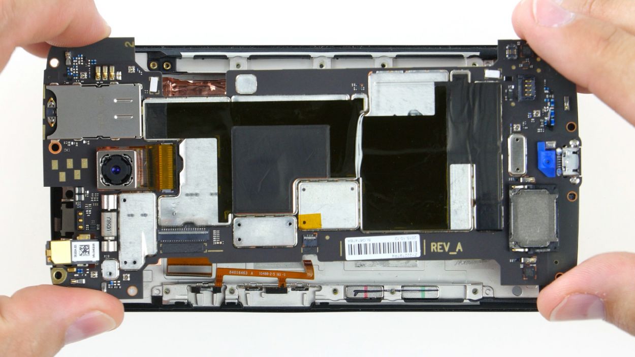
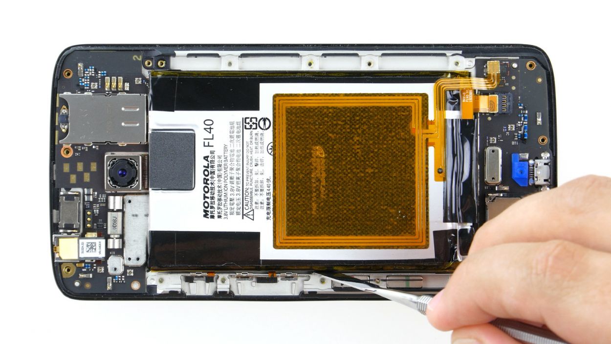
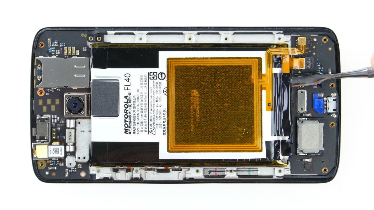
Handle this step with care! Grab a flat, blunt tool like the round end of a steel laboratory spatula to keep that PCB safe and sound.
– First up, let’s warm things up a bit! Use some hot air to gently melt that glue holding everything together.
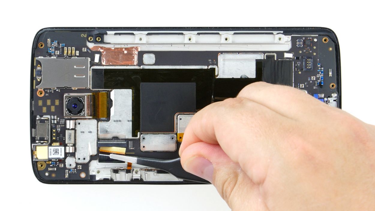
– Now, since the PCB is snugly glued to the enclosure, you’ll want to carefully pry it out. Take your time—nobody wants to accidentally damage any components or the PCB itself!
– Grab your trusty tool and work it around all the edges where you can slide it in to fully detach the PCB.
– Once you can lift the PCB just a tad, slide your tool in a bit deeper to help it along.
– And voilà! It’s time to remove the motherboard from the device.
Step 9
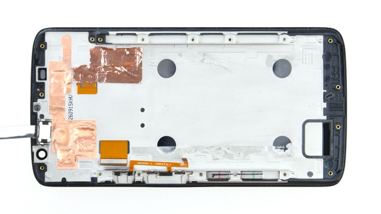
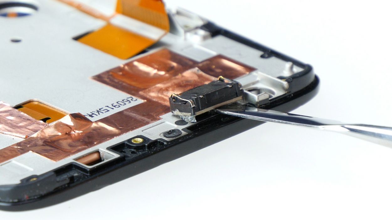
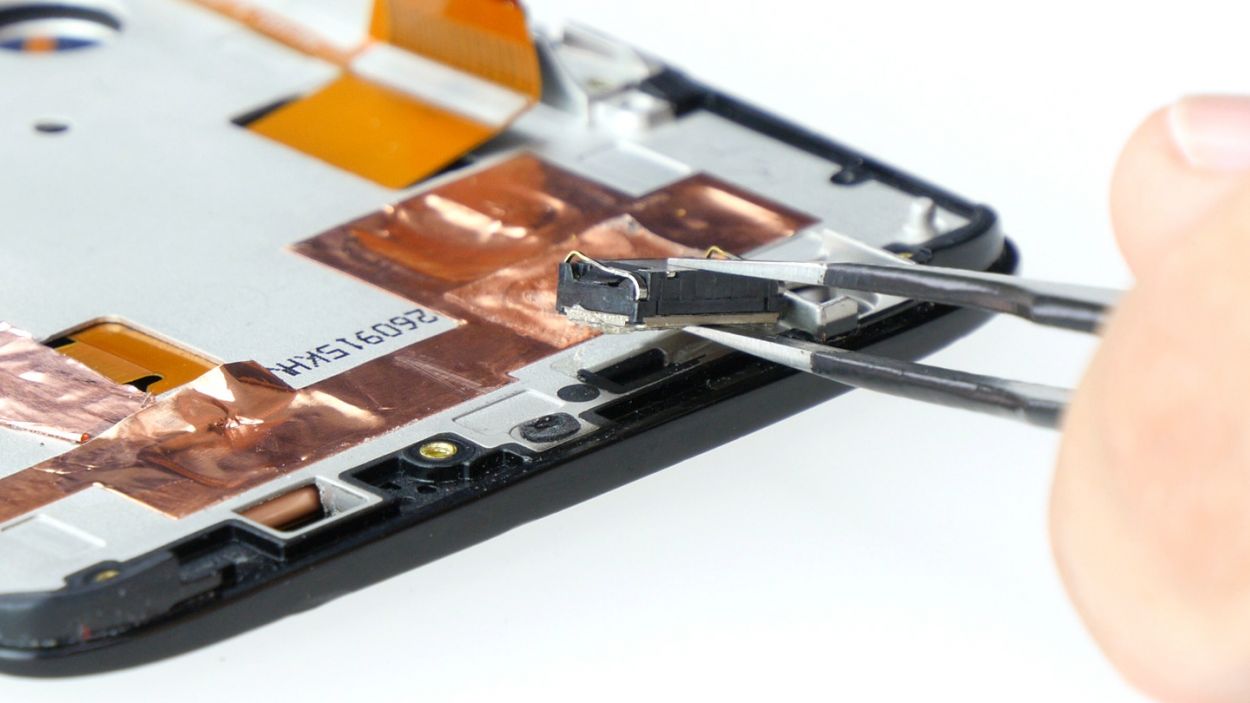
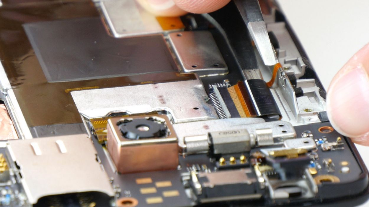
– Alright, let’s locate that earpiece! It’s snugly tucked away in a little recess right in the center of the upper edge of the display frame. It’s got some adhesive keeping it cozy, so grab your steel spatula and gently work your magic to pry it free from its snug spot.
– Once you’ve successfully coaxed it out, go ahead and remove the earpiece completely.
Step 10
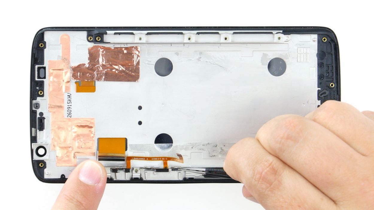
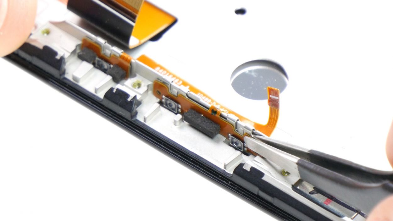


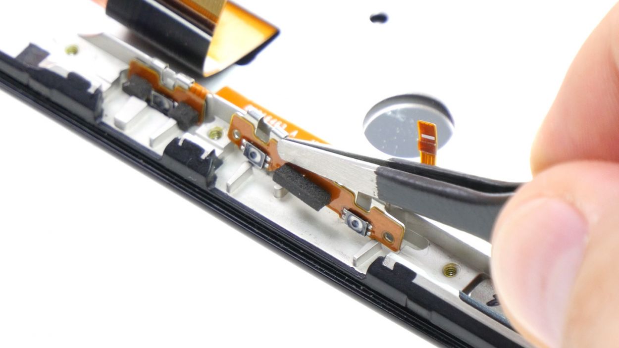
– First up, let’s get those control buttons out of the enclosure! Each of the three buttons is attached to the metal strip with a bracket and secured by a little tab. Grab your tweezers and gently slide them between the button and the strip. Give that bracket a gentle nudge away from the strip, and then slowly lift it up like you’re unveiling a surprise!
– Now, just rinse and repeat for the other two buttons. You’ve got this!
– Next, it’s time to disconnect the volume control cable. Easy peasy!
Step 11


– Place the volume control cable onto the strip. Snap the three brackets into position on the strip.
Step 12
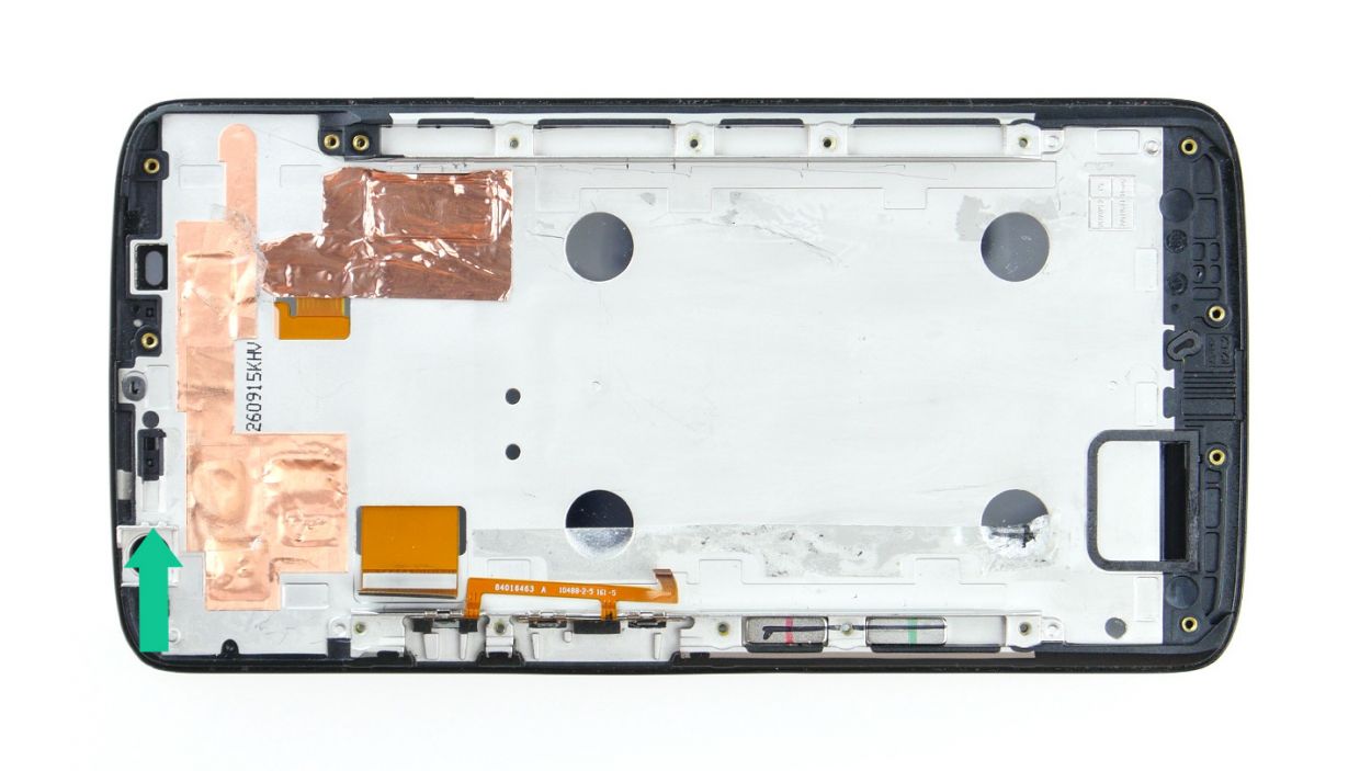

– Place the earpiece snugly into the little nook at the center of the top edge of the display frame. Make sure it sits just right! The black plastic tab on the earpiece should fit perfectly between the two tabs (see the arrow) in the display frame.
– Give that earpiece a good press onto the frame so the glue can do its magic and stick like a champ.
Step 13
– Gently slide the PCB back into its cozy little home in the enclosure, giving it a firm but friendly press so that the glue can stick once more. Just be sure to check that no cables are trying to sneakily hide beneath the PCB. You’re doing great!
Step 14


– First up, let’s connect the display and control button plugs to the PCB. They’re like best buddies that need to stick together!
– Now, gently tuck each cable back into its rightful home in the socket. Make sure to push it all the way in for a solid electrical connection. Remember, no bending or tearing those cables – treat them with care!
– Finally, give those brackets a little press to lock the cables securely in place. You’ve got this!
Step 16

– Reattach the battery contact and the NFC antenna’s connector to the PCB with a gentle touch. It’s time for those connections to reunite! NFC antennaBattery.
– With a little finesse, use your finger to press down on both connectors until they fit snugly into their respective sockets. Listen for that satisfying click—they’re happy to be home!
Step 17


– Carefully place the midframe back onto your device, ensuring that all the openings align perfectly with the threaded holes. It’s like fitting the last piece of a puzzle!
– Grab those seventeen screws and get ready to secure the midframe to your device. Remember, we’re using 17 x 3.1 mm T3 Torx screws here, so let’s make sure they’re nice and snug!
Step 18
– Remember to pop those two buttons back in for the power and volume controls! Just line them up like you see in the first picture and slide them into their cozy little homes. You’ll hear a satisfying click as they lock into place in the enclosure. Easy peasy!
Step 19

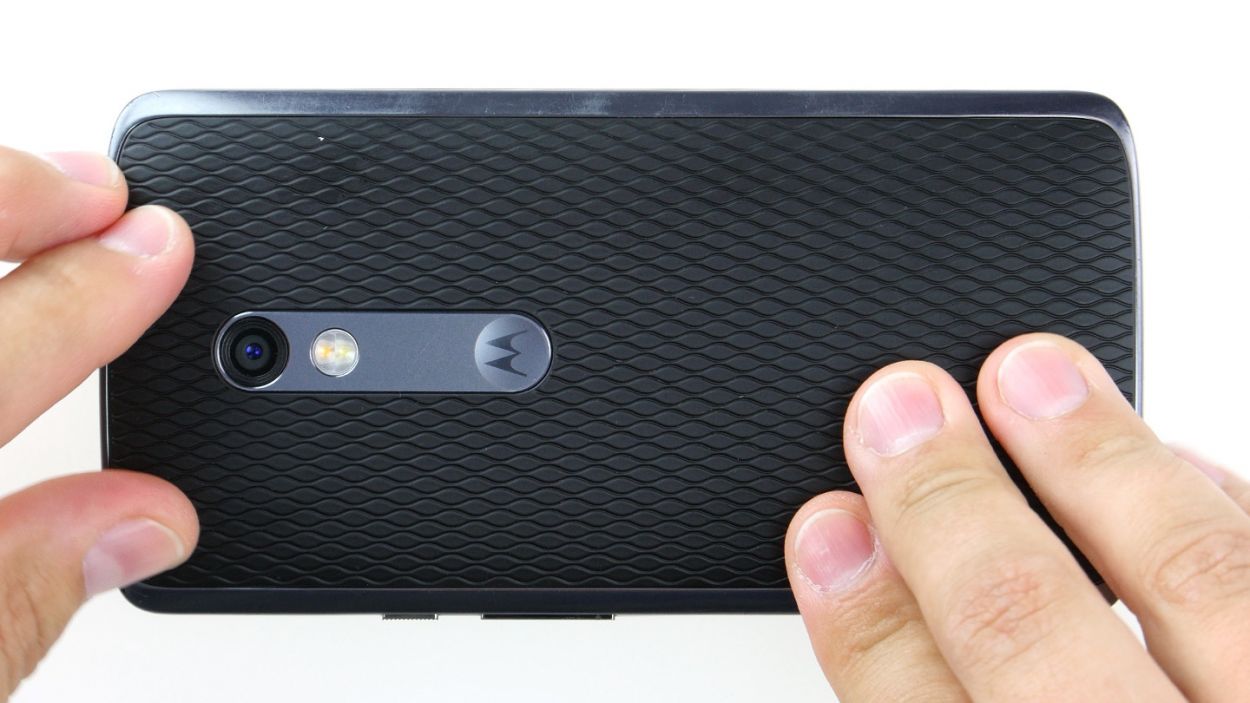
– Get that baby back on there by placing the back cover back in its original spot on the device.
– Press down on it all around until you hear the enchanting clicks of those trusty hooks finally locking into place.
Step 20
– Pop that SIM tray back into your device like a pro! Just make sure it’s lined up just right, and you’re all set!
Step 21
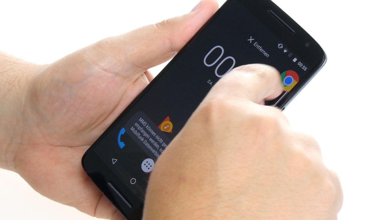
– Get your device fired up and ready to go! Start by giving any app a little dance across the screen. Glide it all around the edges and then throw in some fun zigzag moves across the middle. Just remember, the app should be right there with you, following your finger like a trusty sidekick. Once you’re done showing off, check that display brightness again by sliding that brightness bar all the way to the minimum and then cranking it up to the max. You’re doing great!