How to Replace Nintendo Switch Digitizer: Step-by-Step Guide
Duration: 45 minutes
Steps: 51 Steps
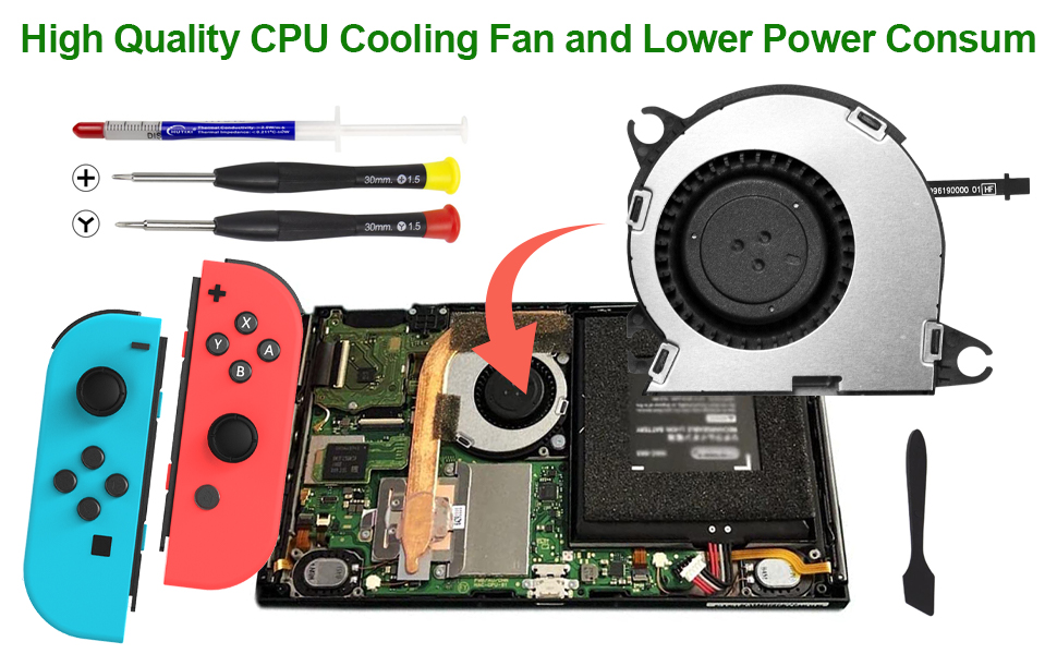
Let’s dive into replacing that busted digitizer on your Nintendo Switch! The Switch rocks JIS screws, but if you’re in a bind, a Phillips screwdriver will do the trick. Just a heads up—handle those screws with care to avoid stripping them. Note: If your screen’s on the fritz, the LCD panel might need replacing instead of the digitizer. Also, when removing the shield plate, be ready to swap out the thermal compound between the plate and the heatsink. Regular thermal paste won’t cut it for larger gaps, so grab some K5 Pro viscous thermal paste. But don’t forget—you’ll still need regular thermal paste for the CPU. Pro tip: While you can complete this repair without taking out the heat sink and game card reader, it does make reconnecting the LCD panel ribbon cable trickier—so plan accordingly. Note: This guide is compatible with both the OG Nintendo Switch from 2017 and the updated model from 2019 (model numbers HAC-001 and HAC-001(-01), respectively). If you hit a wall, you can always schedule a repair!
Step 1


Before diving into this repair adventure, be sure to power down your device completely—let’s keep it chill and safe!
– Give that little round button on the back of your Joy Con controller a good press and hold, like you’re trying to summon a genie!
– While you’re holding that button down, slide the controller up like it’s on a fun little elevator ride.
Step 2


Now it’s time to get the other Joy Con in on the action – just follow the same steps you did for the first one!
– Keep sliding that Joy Con upwards until it’s free from the console. You’ve got this!
Step 3

Keep track of every single screw during this repair—each one has its own little spot to return to, so don’t let them wander off!
– Grab a Y00 screwdriver and unscrew those four 6.3 mm-long screws holding the rear panel in place. Easy peasy, right?
Step 4


To keep those pesky tight screws from stripping, give them some firm downward force, take your time, and try another JIS 000 or PH 000 driver if they’re being stubborn.
– Grab your JIS 000 driver or an official PH 000 driver and let’s get those screws off the rear panel!
– One 2.5 mm-long screw on the top edge of your device
– Two 2.5 mm-long screws on the bottom edge. Easy peasy!
Step 5


– Grab a JIS 000 screwdriver or a PH 000 driver, and pop out the two 3.8 mm center screws on either side of the device—one screw per side. You’ve got this!
Step 6


Before diving into the next step, don’t forget to pop that microSD card out of its cozy little slot. Let’s keep things moving smoothly!
– Give that kickstand a little love—just use your finger to pop it open on the back of the device. Easy peasy!
Step 7

– Grab your trusty JIS 000 screwdriver or a PH 000 driver, and carefully remove that little 1.6 mm screw hiding in the kickstand well.
– Gently close the kickstand to keep everything neat and tidy for the next step.
Step 8


The game card cartridge flap is attached to the other half of the plastic shell, making it tricky to fully lift the rear panel if it’s closed. Just keep that in mind as you work through the steps.
– First, pop open the game card cartridge flap – easy peasy!
– Lift the rear panel up from the bottom of the device and carefully remove it. Take your time, you got this!
Step 9

– Grab your trusty JIS 000 screwdriver or a PH 000 driver and unscrew the 3.1 mm fastener holding down the microSD card reader. Take it slow and steady—you’re doing great!
Step 10


– Grab your fingers or a pair of tweezers to gently lift the microSD card reader straight up from the device to disconnect and remove it. Easy peasy!
– When you’re piecing it all back together, ensure the press connector underneath the foam pad is firmly connected to the motherboard. Removing the foam pad before reinstalling the card reader might make it easier.
Tools Used

Step 11

– Grab your trusty JIS 000 screwdriver or a PH 000 driver and remove the six 3 mm screws holding the shield plate in place. Let’s get this done like a pro!
Step 12


If the foam’s being stubborn and won’t peel away easily, don’t stress! Just give it a little more patience and try peeling from different spots—don’t force it, or it might tear. Slow and steady wins the race.
– Gently use your fingers or a pair of tweezers to lift the foam strip from the top edge of the device, right near the fan exhaust port.
Tools Used
Step 13


A hefty layer of pink thermal compound works its magic between the shield plate and the copper heat sink underneath. It’s the unsung hero keeping your Switch cool and collected.
If you feel a little resistance, don’t sweat it. That’s just the shield plate playing hard to get—it’s lightly bonded to the heat sink with thermal paste.
– Slide a spudger under the shield plate along the device’s edge with a gentle touch.
– Carefully pry it up to lift the shield plate off and set it aside.
– If you’re careful, you can totally reuse that pink thermal compound! Just keep it clean and ensure it makes good contact between the heat sink and the shield when you put everything back together.
– Need to swap it out? No worries! Check out our thermal paste guide to remove the old thermal compound and replace it with a suitable one, like K5 Pro, during reassembly.
Tools Used


Step 14


– Grab your trusty spudger and gently pop the battery connector straight up out of its socket on the motherboard. Easy does it—you’re doing great!
Tools Used
Step 15

– Time to get started! Use a JIS 000 screwdriver or an official PH0000 driver to remove the three 3 mm screws that keep the heat sink attached to the motherboard. Take your time and make sure they’re removed properly.
Step 16
The foam is super sensitive and can rip pretty easily. Here’s a handy tip for peeling it off without a hitch:
Just peel the foam back slightly so it’s out of the fan’s way.
– Gently peel away the two foam pieces from both the heatsink and the fan. They’ve been sticking around a bit too long, so give them some space to breathe.
– Slide the point of your spudger under the part of the foam that’s still hanging on and not stuck down. Be gentle – it’s all about finesse.
– Use your finger to press the top of the foam, keeping it steady so it doesn’t wander off while you work.
– Slowly and carefully roll the spudger tip under the foam from one end to the other, releasing it like a pro.
Tools Used
Step 17


You might notice a little pushback here, and that’s totally cool! It’s just the heat sink giving a gentle hug to the CPU thanks to some thermal paste. No worries, you’re doing great!
– Time to get that heatsink off! Use a spudger or your fingers to carefully lift it up and away from the motherboard.
– Now, let’s get cleaning! Use some high-concentration (90% or higher) isopropyl alcohol and a microfiber cloth to wipe away the old thermal paste from the heat sink and CPU. Then, apply a fresh layer of thermal paste to the CPU – it’s going to love you for it!
– Almost done! Make sure to apply new thermal paste to all the surfaces that had it before, including the area between the heatpipe and aluminum shield. That extra heatsinking power will make your device run smoother than ever.
Tools Used

Step 18


– Grab your opening tool or fingernail and gently flip up the tiny hinged locking flap on the digitizer cable’s ZIF connector—it’s like opening a secret little door!
Step 19


Hey, no need to wrestle with the cable! If it’s being stubborn, double-check that the locking flap is flipped up, adjust the cable’s position, and give it another go.
If your touchscreen is playing hard to get after the repair, but your Game Card reader is still in action, double-check that this cable is snugly inserted. If your Game Card reader is also feeling a bit shy, it’s time to investigate the Game Card connector in the next step.
– Grab your trusty tweezers and slide that digitizer cable out of its connector on the game card reader board with a smooth, horizontal motion.
– Before popping the cable back in during reassembly, ensure the ZIF connector locking flap is flipped up like a pro.
– With the cable running parallel to the board, gently slide it back into its connector. If you need help, you can always schedule a repair.
Tools Used
Step 20


If your touch screen is acting up or game cards aren’t being recognized after putting everything back together, it’s likely that this press connector wasn’t fully reconnected. Give it another go by carefully disconnecting and reconnecting it.
– Use the tip of a spudger to gently pop the headphone jack and game card reader connector straight up—you’re just giving it a little nudge to free it from the motherboard.
– To reconnect, line up the press connectors like you’re aiming for a perfect bullseye. Gently press down on one side until you feel a satisfying click, then do the same on the other side. Avoid pressing the middle—it’s a no-go zone. Misaligned connectors can cause bent pins, and nobody wants that kind of drama.
Tools Used
Step 21

– Grab your trusty JIS 000 screwdriver or the official iFixit PH 000 driver and let’s get to work! Carefully unscrew the three 3.1 mm screws that are holding the headphone jack and game card reader board snugly in place. You’ve got this!
Step 22


– Grab a pair of tweezers or just use your fingers to pop out the headphone jack bracket—it’s easier than it looks!
Tools Used
Step 23


– Grab some tweezers or just use your fingers and gently pluck out the headphone jack and game card reader board like a pro!
Tools Used
Step 24


– Time to get this repair started! Use an opening tool, a trusty spudger, or even your fingernail to carefully flip up that tiny, hinged locking flap on the LCD ribbon cable ZIF connector. It’s easier than you think, and you’re making great progress already!
Tools Used
Step 25


– Grab a trusty pair of tweezers and gently pull the ribbon cable straight out of its cozy connector on the motherboard. You’ve got this!
Tools Used
Step 26


– Time to get this repair started! Use an opening tool, a trusty spudger, or even your fingernail to carefully flip up the tiny, hinged locking flap on the smaller LCD ribbon cable ZIF connector. Take your time, and don’t worry if it takes a little bit of finagling – you’ve got this!
Tools Used
Step 27


– Grab a pair of tweezers and gently pull the ribbon cable straight out of its connector on the motherboard. Take it easy and make sure you’re not yanking, just a smooth pull.
Tools Used
Step 28

Feel free to use a hair dryer, heat gun, or hot plate to loosen things up, but keep it chill—too much heat can mess with the display or battery. Handle with care!
– Warm up an iOpener and place it on the bottom edge of the screen for about two minutes. This little trick will help melt the adhesive and make your task a breeze!
Tools Used

Step 29


If your device has been around for a while, this part might put up a fight. No worries—heat things up a bit more and give it another go!
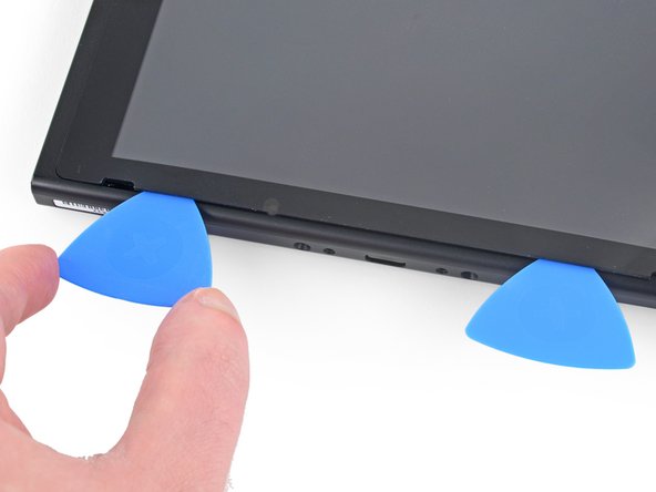
– Grab a suction cup and stick it to the bottom-left corner of the screen.
– Give that suction cup a good pull with steady strength to open up a little gap.
– Carefully slide the tip of an opening pick into that gap, but just a smidge—about 5 mm will do!
Step 30


– Gently glide the opening pick along the bottom edge of the screen to cut through that sticky adhesive.
– Keep the pick in place to stop the adhesive from sticking back to the frame.
Step 31
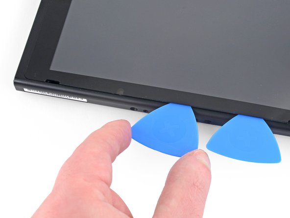

– Pop in a second opening pick right next to the first one, just to the left.
– Gently slide that opening pick back towards the left side of your device.
– Keep that opening pick in place; it’s doing a great job!
Step 32

– Warm up the left edge of the screen for about two minutes to loosen up that stubborn adhesive. A little heat goes a long way here!
Step 33


– Keep gliding that opening pick around the bottom-left corner to neatly slice through the adhesive.
Step 34


– Keep gliding that opening pick along the left side of the screen to cut through the adhesive like a pro!
Step 35

– Warm up the top edge of the screen for about two minutes to gently loosen that sticky adhesive.
Step 36


– Keep cruising with that opening pick around the top-left corner of the screen to slice through the adhesive like a pro.
Step 37


– Keep gliding the opening pick along the top edge of the screen to cut through the adhesive.
Step 38


– Warm up the right edge of the screen for about two minutes to loosen up that stubborn adhesive—kind of like softening butter.
– Slide the flat end of a spudger into the gap along the left edge of the screen. Take it slow—precision is your best friend here.
– Gently lift the left edge of the screen, opening it like you’re flipping through your favorite book. Easy does it!
Tools Used
Step 39


Watch out for those ribbon cables—they’re sneaky! Keep them safe and sound while you lift the screen.
– Gently lift the right edge of the screen straight up and off the device, guiding the ribbon cables through the frame as carefully as threading a needle.
– If the screen adhesive still has some stickiness left, feel free to reuse it. If not, slap on some fresh double-sided adhesive tape, like Tesa tape, to keep things snug and secure.
Step 40
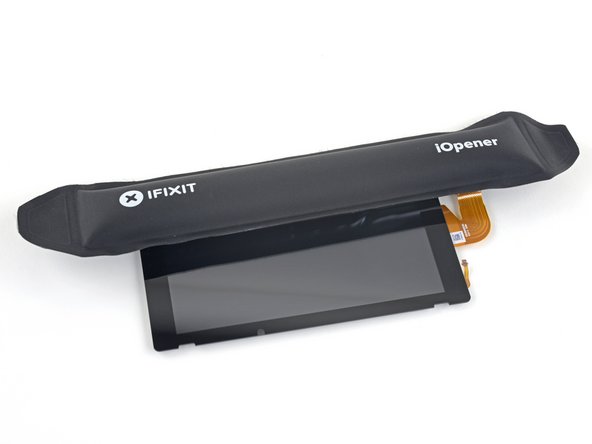
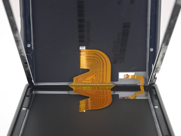
– Warm up the top edge of the screen assembly for about two minutes. This will help loosen the adhesive that’s keeping the LCD panel stuck to the digitizer.
Step 41


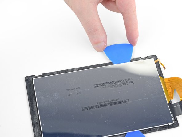
Don’t stress about how deep you shove that opening pick in there; around 5 mm should do the trick to cut through all that sticky stuff.
Feel free to give the digitizer a gentle bend to widen the gap, but be careful not to overdo it—nobody wants to damage it if you’re planning to reuse it!
– Flip the screen assembly over so you’re looking at the back.
– Slide an opening pick gently between the LCD panel and the digitizer at the top-left corner.
– Carefully glide the opening pick along the top edge of the screen assembly to separate the adhesive.
Step 42


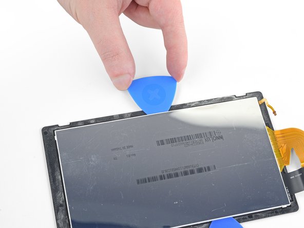
– Keep gliding the opening pick along the top edge of the screen, gently cutting through the adhesive. Take it slow and steady, you’re doing great!
Step 43

– Warm up the left edge of the screen assembly for about two minutes to make that adhesive nice and pliable.
Step 44


– Gently slide the opening pick along the left edge of the screen assembly to cut through the adhesive. Take your time—precision is key!
Step 45


– Now, keep sliding that opening pick around the bottom-left corner of the screen assembly – you’re making great progress! Keep going until you’ve sliced through the adhesive.
Step 46

– Warm up the bottom edge of the screen assembly for about two minutes to loosen the adhesive—think of it like warming up before a workout, but for your phone!
Step 47

– Glide that opening pick along the bottom edge like a pro, slicing through the adhesive with finesse.
Step 48

– Warm up the right edge of the screen assembly for about two minutes to loosen up the adhesive and make your life a little easier.
Step 49


– Gently slide the flat end of a spudger between the LCD panel and the digitizer along the left edge of the screen assembly. You’ve got this!
– With care and a steady hand, lift the left side of the LCD panel as if you’re opening a book. Nice and easy!
Tools Used
Step 50


The LCD ribbon cable is gently attached to the digitizer. If it doesn’t come off easily, apply more heat to that spot and give it another shot.
– Gently keep lifting the LCD panel away from the digitizer—it’s like peeling apart two sticky besties. Take it slow and steady to separate them without any drama.
Step 51

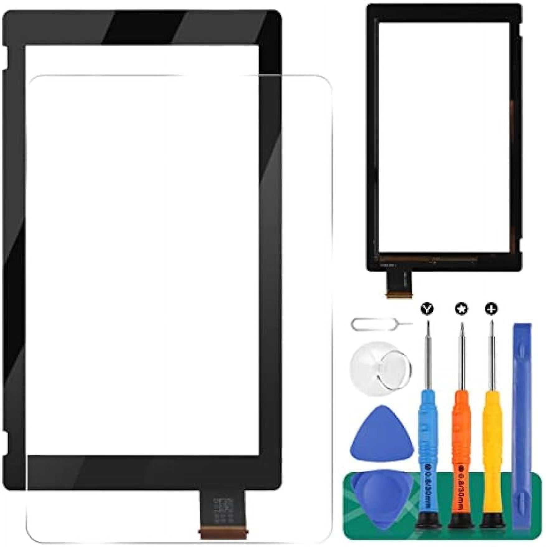
– Match up your new part with the old one—sometimes you need to move over leftover pieces or peel off protective layers from the replacement before popping it in.
– To put everything back together, just reverse these steps and you’re good to go!
– If the digitizer feels off after powering up, don’t sweat it—power down, unplug the battery connector, and plug it back in. Easy fix!
– Recycle your e-waste responsibly at an R2 or e-Stewards certified facility. Let’s keep it green!
– Got stuck or things didn’t go as planned? Don’t panic—try troubleshooting or swing by the Nintendo Switch Answers community for some expert tips.
– Feeling like this repair is a bit much? No worries—if you need backup, you can always schedule a repair.
Success!