How to Replace Nintendo Switch Midframe: Step-by-Step Guide
Duration: 45 minutes
Steps: 87 Steps
If your midframe has seen better days—like when a joy-con mounting rail gets torn away and leaves no solid spot to attach a replacement rail—then it’s time for a midframe makeover. To get your Switch back to top gaming condition, you’ll need to replace the entire midframe. This guide will walk you through every step with ease. Heads-up: When taking off the shield plate, remember to swap out the thermal compound between it and the heatsink. Regular thermal paste won’t cut it for large gaps, so go for K5 Pro viscous thermal paste. For the CPU, though, regular replacement thermal paste will do just fine.
Step 1


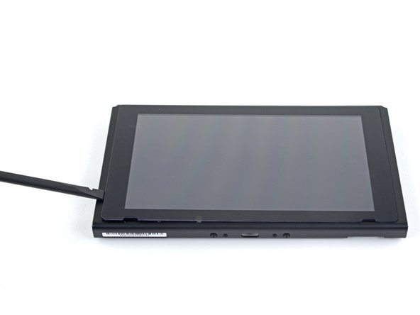
Before diving into this repair, make sure your device is powered off completely. We don’t want any surprise restarts in the middle of the process!
– Give that small round button on the back of the Joy-Con controller a firm press and hold.
– Keep the button pressed as you smoothly slide the controller upwards.
Step 2


Go ahead and tackle the same steps for the other Joy Con! You’ve got this!
– Keep sliding that Joy Con up until it’s free from the console, just like a bird taking flight!
Step 3

Keep each screw organized to ensure correct placement later.
– Grab a Y00 screwdriver and take out the four 6.3 mm screws holding the rear panel in place. You’ve got this!
Step 4


To keep those pesky screws from stripping, press down firmly while you work your magic. Take your time and if the screws are being stubborn, give a JIS 000 or PH 000 driver another shot. You’ve got this!
– Grab a JIS 000 driver or the official PH 000 driver to loosen the screws holding the rear panel:
– One 2.5 mm-long screw on the top edge of the device
– Two 2.5 mm-long screws on the bottom edge of the device
Step 5


– Grab a JIS 000 screwdriver or an official PH 000 driver from iFixit, and let’s tackle those pesky center screws together! There are two 3.8 mm screws, one on each side of your device, just waiting to be removed. You’ve got this!
Step 6


Before diving into the next step, make sure to pop out that microSD card from its cozy little slot. Trust us, it’ll make things smoother sailing from here!
– Gently pop out the kickstand on the back of your device with your finger—it’s like giving your gadget a little stretch break!
Step 7

– Grab your trusty JIS 000 screwdriver or the official iFixit PH 000 driver and gently unscrew that 1.6 mm screw nestled in the kickstand well.
– Now, go ahead and close the kickstand.
Step 8


The game card cartridge flap hooks onto the other half of the plastic shell, so you’ll need to pop it open before you can lift up the rear panel.
– Flip open the game card cartridge flap like you’re opening a tiny treasure chest.
– Gently lift the rear panel from the bottom of your device—carefully now—and slide it off like a pro.
Step 9

– Grab your trusty JIS 000 screwdriver or the official iFixit PH 000 driver and gently unscrew the 3.1 mm screw that’s holding the microSD card reader in place. You’ve got this!
Step 10


– Time to get that microSD card reader out! Use your fingers or a trusty pair of tweezers to carefully lift it straight up from the device. This will disconnect and remove it – easy peasy!
– When you’re putting everything back together, make sure the press connector under the foam pad is securely connected to the motherboard. If it helps, you can remove the foam pad before reinstalling the card reader to get a better look.
Tools Used

Step 11

– Grab a JIS 000 screwdriver or the official iFixit PH 000 driver and get ready to tackle those six 3 mm screws holding the shield plate in place. You’ve got this!
Step 12


If the foam is being stubborn and doesn’t want to peel away easily, don’t stress it! Forcing it might just lead to a tear. Instead, try gently peeling from different spots to coax it back.
– Gently use your fingers or a trusty pair of tweezers to lift the foam piece at the top edge of your device, right by the fan exhaust port. You’ve got this!
Tools Used
Step 13


There’s a chunky pink layer of thermal goop connecting the shield plate to the copper heat sink below. It’s a clever little trick to keep the Switch cool as a cucumber.
You might feel a bit of a tug when removing the shield plate. No worries—that’s just the thermal paste doing its thing, keeping things snug and secure.
– Slide a spudger under the shield plate along the edge of the device—be gentle, it’s not a race!
– Pop that shield plate up by prying carefully, then lift it off and set it aside like the superstar repairer you are.
– The pink thermal compound can be reused if you handle it with care—keep it clean and make sure it has solid contact between the heat sink and the shield when you put it back together.
– If replacing the thermal compound is more your style, check out our thermal paste guide to swap out the old stuff for something fresh, like K5 Pro, during reassembly. Keep it cool, literally!
Tools Used


Step 14


– Gently use the tip of a spudger to lift the battery connector straight up and out of its cozy spot on the motherboard. You’ve got this!
Tools Used
Step 15


Before diving in with that adhesive remover, let’s get prepped and ready to rock! Follow these simple preparation steps first.
– Drip a bit of adhesive remover or some high-octane (90% or higher) isopropyl alcohol into the battery well along the top edge to loosen up that stubborn adhesive.
Tools Used

Step 16


– Gently rock the top edge of your device upward to let the isopropyl alcohol shimmy its way underneath the battery.
– Hang tight for 1-2 minutes while the isopropyl alcohol loosens up that stubborn adhesive.
Tools Used
Step 17


Be gentle and steer clear of puncturing or bending the battery—trust us, a damaged battery can leak nasty stuff or even cause a fiery situation.
– Wedge an opening pick into the space between the battery and the side of the battery compartment.
– Gently nudge the tip of the pick under the battery and glide it along the edge to start loosening the adhesive.
Step 18

– Keep that opening pick in place, and go ahead and drop a little more adhesive remover or isopropyl alcohol into the battery well. Let it do its thing!
– Tilt the top edge of your device upward and give it 1-2 minutes to let the alcohol work its magic and loosen up that stubborn adhesive.
Tools Used
Step 19

– Slide the opening pick a little deeper along the top edge of the battery, cutting through more of the adhesive beneath it. Keep going, you’re almost there!
Step 20


Handle the battery with care while prying; nobody likes a bent battery!
Once the battery’s been removed, it’s time to say goodbye to it—reusing it could lead to some serious safety issues. Grab a shiny new battery instead!
If you’re having a tough time prying things apart, don’t hesitate to add a little more isopropyl alcohol to help things along.
– When you’ve made enough space, gently slide a plastic card under the battery and nudge it up with care.
– Now, go ahead and take out the battery.
Tools Used
Step 21

In case your shiny new battery didn’t come with its own sticky support, no worries! Just follow this handy guide to stick on some pre-cut adhesive at the bottom of your battery, and you’re all set for a smooth installation.
– Grab some adhesive remover or good ol’ isopropyl alcohol and a trusty microfiber cloth to wipe out any leftover sticky gunk in the battery well. Make it nice and clean before you pop in the fresh new battery—your device will thank you!
Tools Used
Step 22

– Grab your trusty JIS 000 screwdriver or the official PH 000 driver from iFixit, and let’s tackle those three 3 mm screws holding the heat sink snugly to the motherboard. You’ve got this!
Step 23
Be gentle with that foam! It’s super delicate and can tear easily. To remove it safely, follow this simple technique:
Just peel back the foam just enough to give the fan some breathing room. No need to go overboard, just a little space is all it needs.
– Let’s get started by carefully prying the two foam pieces away from the fan and heatsink – it’s like peeling a sticker, but gently!
– Slide the point of a spudger under the foam that’s not stuck to anything, and get ready to set it free!
– Use your finger to hold the top of the foam in place, and then use the spudger to roll underneath and release the foam all the way to the other end – you got this!
– Keep going, you’re doing great! Roll the spudger tip underneath the foam until it’s completely released – nice job!
Tools Used
Step 24


You might feel a little resistance here – don’t worry, it’s totally normal! The heat sink is just lightly stuck to the CPU with thermal paste. Give it a gentle wiggle and you should be good to go!
– Gently use a spudger or your fingers to lift the heatsink off the motherboard. It’s like giving it a little nudge to free it up.
– Grab some high-concentration (90% or higher) isopropyl alcohol and a microfiber cloth to wipe away the old thermal paste from both the heatsink and the CPU. Don’t forget to add a fresh layer of thermal paste to the CPU before putting everything back together.
– Be sure to apply thermal paste to all areas that had it before, including between the heatpipe and the aluminum shield. This part helps keep your device cool with that extra heatsinking action!
Tools Used
Step 25


– Grab an opening tool or just your trusty fingernail, and gently flip up the tiny hinged locking flap on the digitizer cable’s ZIF connector—easy does it!
Step 26


Don’t try to muscle the cable into the connector! If it’s not going in, make sure the locking flap is flipped up, adjust the cable’s position, and give it another shot. If you need help, you can always schedule a repair
If your touchscreen is playing hard to get after the repair but your Game Card reader is still in the game, double-check that this cable is snugly in place. If your Game Card reader is also giving you the cold shoulder, it’s time to investigate the Game Card connector in the next step.
– Grab a trusty pair of tweezers and gently slide the digitizer cable sideways out of its connector on the game card reader board—like you’re easing a VIP past a velvet rope.
– When putting the cable back during reassembly, double-check that the ZIF connector’s locking flap is flipped up and ready to welcome it in.
– Keep the cable lined up parallel to the board, and with all the finesse of a pro, glide it smoothly into its connector.
Tools Used
Step 27


If the touch screen isn’t responding or the game cards aren’t showing up after putting everything back together, it’s possible that this press connector didn’t make a full connection. Go ahead and disconnect it, then give it another shot.
– Grab a spudger and gently lift the headphone jack and game card reader connector straight up to pop it off the motherboard. Easy-peasy, no sweat!
– When reconnecting, here’s the trick: align it carefully, press down on one side until it clicks, then do the same on the other side. Avoid pushing on the middle—nobody likes bent pins, and trust me, misaligned connectors can cause some serious headaches. Keep it smooth and steady!
Tools Used
Step 28

– Grab your trusty JIS 000 screwdriver or an official PH 000 driver and carefully remove the three 3.1 mm screws that are keeping the headphone jack and game card reader board in place. Take your time, no rush!
Step 29


– Grab a trusty pair of tweezers or simply use your fingers to gently pop off the headphone jack bracket. You’ve got this!
Tools Used
Step 30


– Grab a pair of tweezers or just use your fingers to gently pop out the headphone jack and the game card reader board. Easy-peasy!
Tools Used
Step 31


– Grab your trusty opening tool, spudger, or even your fingernail and give a little lift to that small, hinged locking flap on the LCD ribbon cable ZIF connector. You’ve got this!
Tools Used
Step 32


– Grab those trusty tweezers and gently slide the ribbon cable out of its connector on the motherboard. Slow and steady wins the race!
Tools Used
Step 33


– Grab an opening tool, a spudger, or even your trusty fingernail, and carefully flip up the little hinged locking flap on the fan cable ZIF connector. Take your time—this step needs a gentle touch!
Tools Used
Step 34


– Grab a trusty pair of tweezers and gently tug that fan cable straight out from its connector on the motherboard—easy does it!
Tools Used
Step 35


– Grab an opening tool, spudger, or even your trusty fingernail to pop up the tiny, hinged locking flap on the power and volume button ribbon cable ZIF connector.
Tools Used
Step 36


– Time to get a little delicate! Use a trusty pair of tweezers to carefully pull the ribbon cable straight out of its connector on the motherboard. Take your time, and it’ll come out smoothly.
Tools Used
Step 37


– Grab your trusty opening tool, spudger, or even your fingernail, and carefully pop open the small, hinged locking flap on the smaller LCD ribbon cable ZIF connector. Slow and steady wins the race!
Tools Used
Step 38


– Grab your trusty tweezers and gently pull the ribbon cable straight out of its connector on the motherboard. Just a smooth, steady motion—no need to rush!
Tools Used
Step 39


– Grab a spudger, an opening tool, or just your trusty fingernail, and gently flip up that tiny hinged locking flap on the Joy Con sensor rail’s data cable ZIF connector like a pro.
Tools Used
Step 40


– Grab a trusty pair of tweezers and gently pull the ribbon cable straight out of its cozy connector on the motherboard. You’ve got this!
Tools Used
Step 41


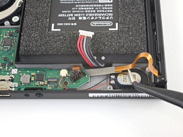
– Grab your trusty spudger and gently pop that black antenna cable straight up out of its socket on the motherboard—easy does it, you’re doing awesome!
Tools Used
Step 42


– Grab your trusty spudger and gently lift the white antenna cable straight up from its cozy spot on the motherboard. You’ve got this!
Tools Used
Step 43


Handle the connector with care and avoid tugging on the speaker wires. They’re super delicate and can easily break off the connector.
– Gently pull the right speaker connector straight out of its socket on the motherboard using your fingers or a trusty pair of tweezers. Take your time and be careful not to touch any other components.
Tools Used
Step 44


Handle those speaker wires with care! They’re super delicate and can easily break off the connector if you tug on them too hard.
– Gently grab the left speaker connector with your fingers or a trusty pair of tweezers and pull it straight out of its cozy socket on the motherboard. You’ve got this!
Tools Used
Step 45


– Time to get this repair started! Use an opening tool, spudger, or even your trusty fingernail to carefully flip up the small, hinged locking flap on the Joy Con sensor rail data cable ZIF connector. Take your time, it’s easier than you think!
Tools Used
Step 46


– Grab your trusty tweezers and gently coax the Joy Con rail data cable straight out of its connector on the motherboard—steady hands, you got this!
Tools Used
Step 47

– Grab yourself a trusty JIS 000 screwdriver or a PH 000 driver—whichever’s in your toolkit—and get ready to tackle these screws:
– Four 2.5 mm screws
– Two 3.1 mm screws
Step 48


– Slide a spudger into the little gap between the motherboard and the frame—it’s like giving it a gentle nudge!
– Carefully lift the motherboard up and out of the frame, like you’re unveiling a surprise. You’ve got this!
Tools Used
Step 49


Handle the connector with care and avoid tugging on the speaker wires. They’re super delicate and can easily break off the connector.
– If you’re just swapping out the left speaker, feel free to breeze past the next two steps.
– Gently use your fingers or grab a pair of tweezers to carefully pull the speaker connector straight out of its cozy little socket on the motherboard.
Tools Used
Step 50
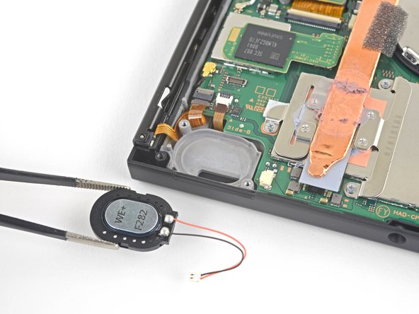


The speaker is lightly stuck in place with some adhesive inside the speaker well, so you’ll need a little elbow grease to get it out.
– Grab your trusty spudger and gently nudge the speaker up with its pointy end. You’ve got this!
– Now, use your fingers or a pair of tweezers to carefully lift out the right speaker. Easy peasy!
Step 51


Avoid tugging on the connector by the speaker wires. They’re delicate and can easily break off the connector.
Ready to rock? Let’s knock out these next three steps to swap out the left speaker.
– Gently grab the speaker connector with your fingers or a trusty pair of tweezers and pull it straight out of its cozy socket on the motherboard. You’ve got this!
Tools Used
Step 52


The speaker is lightly glued in the speaker well, so you’ll need to use a bit of muscle to get it out.
– Grab your trusty spudger and gently pop up that speaker to loosen it from its cozy little spot in the speaker well.
Tools Used
Step 53


– Gently use your fingers or a trusty pair of tweezers to lift the speaker out of its cozy spot in the speaker well. You’ve got this!
Tools Used
Step 54

– Grab your trusty JIS 000 screwdriver or an official PH 000 driver and get ready to tackle those screws! Remove the three 4.8 mm screws that are holding the fan in place.
Step 55

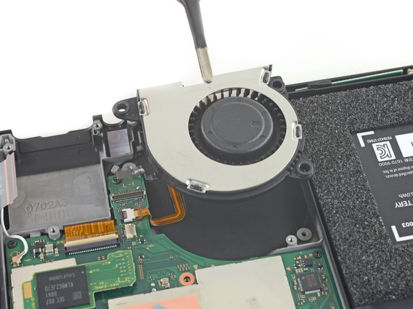
Line up your shiny new replacement part next to the original one for a quick side-by-side. If there are any bits and pieces left behind (like those rubber bushings), go ahead and transfer them over to the new part before you get it all set up.
– Grab a trusty pair of tweezers or just your fingers, and gently lift the fan straight up to free it from the device. You’ve got this!
Tools Used
Step 56

These screws are really on there, so they might put up a bit of a fight. To keep them from getting stripped, apply a strong downward pressure, take your time, and don’t hesitate to switch to a different screwdriver if they just won’t budge.
– Grab your trusty JIS 000 screwdriver or the official iFixit PH 000 driver, and let’s get to work! Carefully unscrew those four 3.7 mm screws that are holding the right Joy Con rail snugly to the device’s frame. You’ve got this!
Step 57


Be careful when removing the rail – make sure the data cable doesn’t get caught on the device frame.
– Carefully detach the right Joy Con sensor rail.
Step 58


– Grab your fingers or a trusty pair of tweezers, and gently pop the battery connector up and away from the Joy-Con rail’s data cable. Keep it chill and steady—you got this!
Tools Used
Step 59

– Time to get a little handy! Use your fingers or a trusty pair of tweezers to carefully lift the battery connector up and out of the way of the Joy Con rail’s data cable. Nice and gentle does the trick!
Tools Used
Step 60

These screws are in there tighter than a jar of pickles! To avoid stripping them, press down firmly, take your time, and if they still won’t budge, grab another screwdriver and give it a go.
– Grab your JIS 000 screwdriver or your trusty PH 000 driver and unscrew the four 3.7 mm screws holding the left Joy-Con rail to the device frame. Steady hands, friend—you’re doing awesome!
Step 61


– Detach the left Joy-Con sensor rail from the device with confidence and precision.
Step 62

– Time to get that power/volume ribbon cable loose! Use the flat end of a spudger to gently pry it up from its taped-down position.
Tools Used
Step 63


– Gently pop out the power/volume board using a pair of blunt nose tweezers—steady hands win the day!
Tools Used
Step 64

– Gently grip the rubber conductive pad with a pair of blunt nose tweezers and carefully pull it out.
Tools Used
Step 65

– Gently wiggle out the power and volume buttons using a pair of blunt nose tweezers. You’ve got this!
Tools Used
Step 66


– Gently untangle and free up the black coax cable from the midframe.
Step 67


– Keep on trucking along that wire, gently derouting it as you make your way along!
Step 68


– Lift up the metal barrel around the coax from the midframe—steady hands win the day!
Step 69


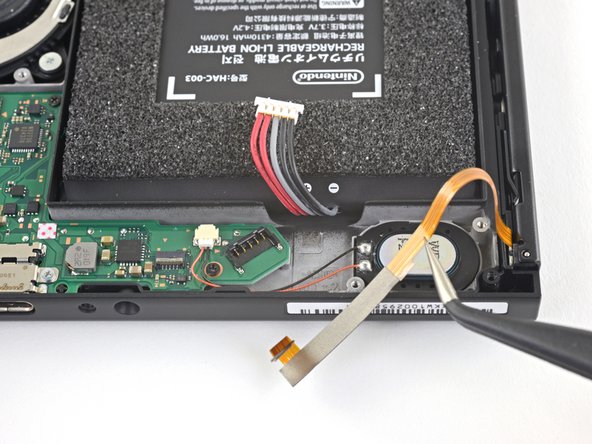
– Pinch that WiFi antenna board gently with your tweezers, lift it straight up, and voilà—it’s out!
Tools Used
Step 70

You can use a hair dryer, heat gun, or hot plate, but play it cool—too much heat can harm the display or battery.
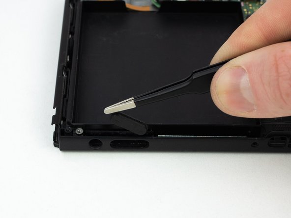
– Let’s get started! Heat an iOpener and apply it to the bottom edge of the screen for about two minutes. This will help loosen the adhesive, making the next steps a whole lot easier.
Tools Used

Step 71


Depending on how old your device is, this step might be a bit tricky. If you’re having trouble, no worries—just add a little more heat and give it another go.
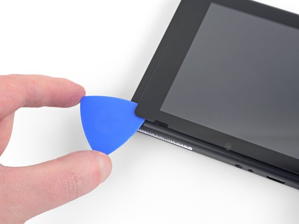
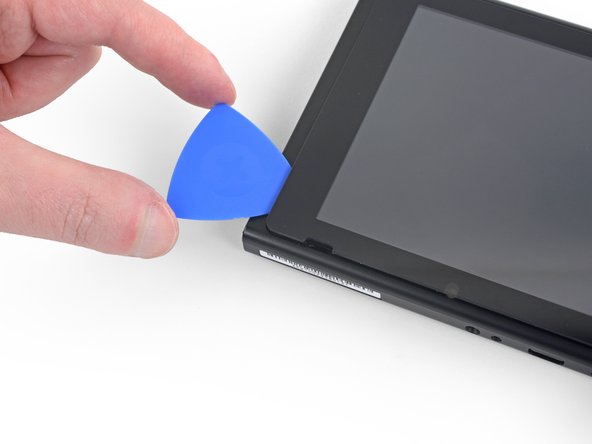
– Get a grip on that screen by applying a suction cup to the bottom-left corner – it’s go time!
– Pull up on the suction cup with some strong, steady force to create a gap – you’re making progress!
– Carefully insert the point of an opening pick into the gap, just about 5 mm, and you’re on a roll! If you need help, you can always schedule a repair
Step 72


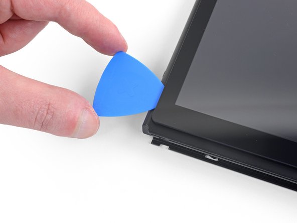
– Glide that opening pick smoothly along the bottom edge of the screen to cut through the adhesive like a pro.
– Keep the pick chilling in place to stop the adhesive from sticking back to the frame.
Step 73


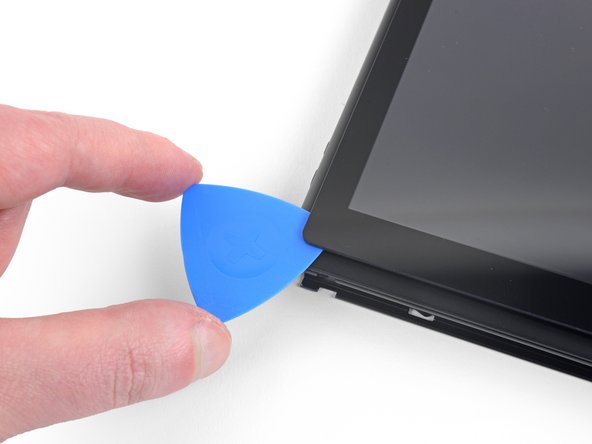
– Pop in a second opening pick right next to the first one, just to the left.
– Gently slide that opening pick back towards the left side of your device.
– Keep that opening pick in place; it’s doing a great job!
Step 74

– Warm up the left edge of the screen for about two minutes—that adhesive needs a little loosening up, like stretching before a workout.
Step 75

– Keep pushing that opening pick around the bottom-left corner to cleverly slice through the adhesive.
Step 76


– Glide that opening pick smoothly along the left edge of the screen to slice through the adhesive like a pro.
Step 77

– Let’s get this repair started! Heat the top edge of the screen for about two minutes to loosen up that adhesive. This will make the next steps a whole lot easier.
Step 78

– Glide that pick smoothly around the top-left corner of the screen to cut through the adhesive like a pro.
Step 79


– Keep gliding that opening pick along the top edge of the screen to slice through the adhesive like a pro.
Step 80

– Warm up the right side of the screen for about two minutes to make that adhesive a bit easier to work with.
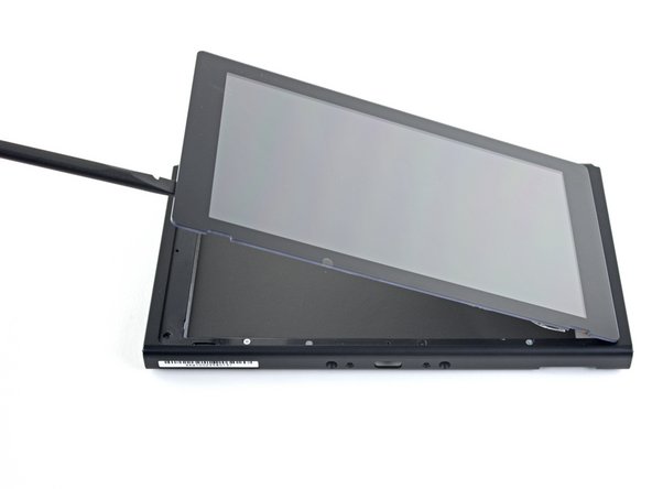
– Gently slide the flat end of a spudger into the gap along the left side of the screen.
– Slowly and carefully lift the left side of the screen, opening it just like a book.
Tools Used
Step 81


Be gentle as you lift the screen out—those ribbon cables are like delicate little dancers, and you don’t want to mess up their groove!
– Gently lift the right edge of the screen straight up and off the device, making sure to guide those ribbon cables smoothly through the frame—like threading spaghetti through a fork!
– If the adhesive under the screen still has some stickiness left, feel free to reuse it. If not, swap it out with some trusty double-sided tape, like Tesa tape, to keep everything snug.
Step 82

– Unscrew those four little guys holding the front frame to the midframe—it’s like giving your device a mini makeover!
Step 83
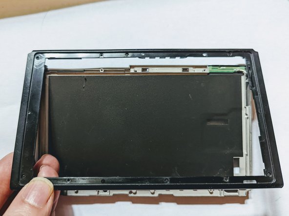
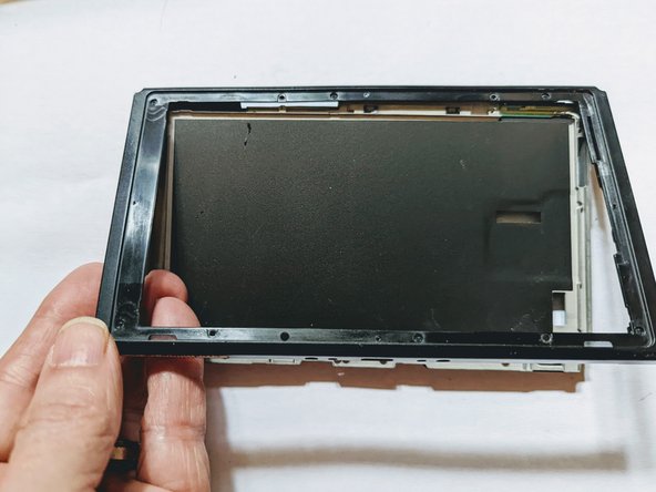

– Gently lift the front edge of the frame and then slide it upwards towards the top of the display to pop it off. You’re doing great!
Step 84

– Make sure the coax wire is all clear—no blockages or funky routing inside the device.
Step 85


– Gently grab the antenna and pull it up to release – it’s held in place with some light adhesive, so it should come loose easily.
Step 86

Replacement antennas might not have the black plastic support piece, so you’ll need to transfer it from the old one to the new one.
– Slide that coax cable smoothly through the frame slot—like threading a needle but way cooler!
Step 87
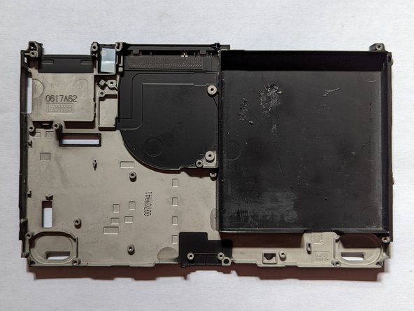

Many new midframes don’t come with that handy black insulation layer between the midframe and screen. No worries, you can either find a suitable substitute or try to rescue the layer from your old midframe.
– Put your device back together by reversing these steps—easy peasy!
– If you hit a snag or need a hand, you can always schedule a repair.
Success!