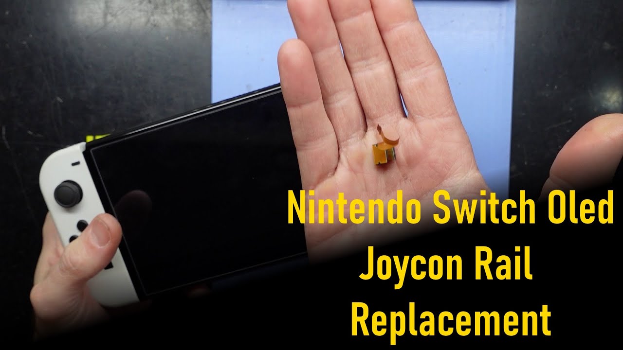
How To Replace Nintendo Switch OLED Screen: Step-by-Step Guide
Duration: 45 minutes
Steps: 63 Steps
To keep things safe and smooth, make sure to drain the battery below 25% before cracking open your Switch.
Get ready to swap out the screen OLED assembly in your Nintendo Switch OLED! This assembly comes with the frame, OLED panel, and speakers all set to go. If you’re just looking to replace the OLED panel on its own, check out a different guide for that. Safety first! Make sure to drain your battery below 25% before diving in—this helps prevent any fiery mishaps if the battery gets a little too adventurous during the repair. If your battery looks like it’s puffing up, take the necessary precautions. The Switch OLED uses JIS screws, but if you find yourself in a pinch, a Phillips screwdriver will do the trick. Just be gentle with those screws—nobody likes a stripped screw! Our Phillips bits are made to work well with JIS-style screws, so you’re covered. Quick tip: when you take off the shield plate, don’t forget to replace the thermal compound between the plate and the heatsink. Regular thermal paste isn’t quite up to the task of bridging those gaps, so grab some K5 Pro viscous thermal paste instead. And remember, you’ll need standard thermal paste when swapping out the heatsink. If you hit a snag, don’t hesitate to schedule a repair!
Step 1


Before diving into this repair adventure, ensure your device is totally powered down and ready for action.
– Grab the small, round button on the back of the Joy Con controller and give it a nice press.
– While you’re holding it down, slide that controller up. Smooth moves!
Step 2


Now, rinse and repeat for the other Joy-Con! You got this!
– Keep sliding that Joy Con up until it pops out of the console!
Step 3


Keep those screws in check! Press down firmly, go slow, and if they’re being stubborn, switch up your JIS or Phillips driver for better results.
– Grab your trusty Phillips or JIS driver and unscrew the 2mm-long screw holding the top of the rear case to the frame. You’re almost there!
Step 4


– Let’s get started! Use a Phillips driver to carefully remove the two 2mm-long screws that hold the bottom of the rear case in place. This is the first step in freeing up the case from the frame, and we’re excited to help you get your device fixed!
Step 5


Keep those tiny screws intact! Press down firmly, take it slow, and if they’re being stubborn, try a different JIS 000 or PH 000 screwdriver for better luck.
– Grab your Phillips driver and unscrew the 3.8mm screw holding the right Joy-Con sensor rail to the rear case. It’s a small step, but it gets you closer to the goal!
Step 6


– Grab your trusty Phillips driver and pop out the 3.8 mm screw holding the left Joy-Con sensor rail to the rear case. Easy peasy!
Step 7


Hey there! If you’ve spotted a microSD card chillin’ in the slot, go ahead and take it out before we dive into the next step. You’ve got this!
– Give that kickstand a gentle nudge with your finger and watch it pop up from the back of your device!
Step 8


– Grab your trusty Y00 screwdriver and unscrew the two 4.3 mm screws holding the rear case to the frame. Easy peasy!
Step 9


If the case is being stubborn, grab an opening pick to gently pop those plastic clips loose.
– Gently lift the rear case from the top of your device and take it off with care.
Step 10


– Gently pry up one corner of the tape from the shield plate using the flat end of a spudger.
Tools Used

Step 11


– Grab your trusty tweezers or just use your fingers to gently peel back and take off that tape.
– Find a clean spot to keep the tape safe for when it’s time to put it back on.
Tools Used

Step 12


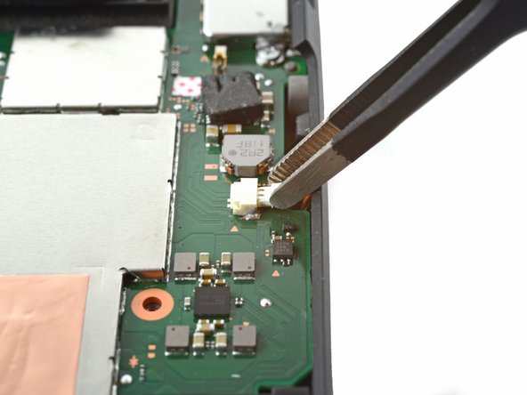
– Grab your tweezers or just use your fingers to carefully lift and pop off the primary Wi-Fi antenna’s coaxial cable. Easy does it, no rush here!
– When you’re putting it all back together, reconnecting these tiny connectors can be a bit of a dance. Focus on one at a time—hold the connector over its socket, then press it down gently with the flat end of a spudger. You’ll hear a satisfying snap when it’s seated perfectly.
Step 13


– Grab those tweezers or just use your fingers to gently guide the primary antenna’s coaxial cable out of its cozy little slots in the shield plate. You’ve got this!
Tools Used
Step 14


– Grab your trusty Phillips driver and unscrew those two 4.4 mm screws holding the primary Wi-Fi antenna to the shield plate. You’ve got this!
Step 15


– Slip an opening pick between the main Wi-Fi antenna and the shield plate.
– Gently pry with the pick to lift the Wi-Fi antenna off the shield plate.
Step 16


– Gently pop off the main Wi-Fi antenna—go on, you’re doing great!
Step 17


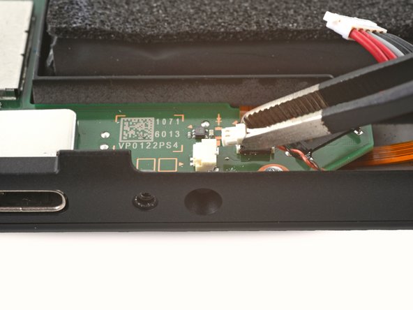
– Gently grab the secondary Wi-Fi antenna’s coaxial cable with tweezers or your fingers, and carefully disconnect it.
Tools Used
Step 18


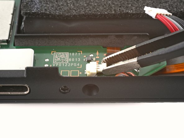
– Grab your trusty spudger and gently use its point to guide the secondary Wi-Fi antenna’s coaxial cable out of its cozy spot in the frame. Keep it cool, no need to rush!
Tools Used
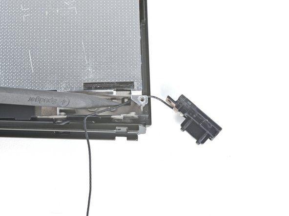
Step 19


– Grab a Phillips driver and twist out that 4.4 mm screw holding down the secondary Wi-Fi antenna on the shield plate.
Step 20


Hold up! Don’t yank the antenna out just yet—its coaxial cable is still snaking its way through the frame.
– Slide an opening pick between the secondary Wi-Fi antenna and the shield plate—nice and easy!
– Gently pry upward with the pick to pop the secondary Wi-Fi antenna free from the shield plate. You’re doing great!
Step 21


– Grab your trusty spudger and gently lift the secondary Wi-Fi antenna’s coaxial cable out of its snug little slot in the frame.
– Carefully take out the secondary Wi-Fi antenna.
Tools Used
Step 22


– Grab your trusty Phillips driver and remove the six 4.4mm screws that are holding the shield plate in place. Take your time, and remember, those screws are like the keys to the treasure chest. Once they’re out, you’re one step closer to your goal.
Step 23


You might encounter a bit of pushback, which is totally normal. The shield plate is snugly attached to the heat sink with some thermal paste.
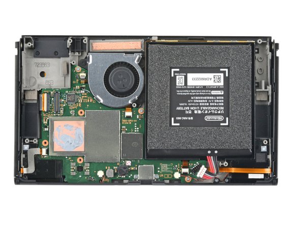
– Time to get this repair started! Use your fingers to carefully pry the top of the shield plate away from the frame – it’s like opening a little door.
– Now, completely remove the shield plate. You’re making great progress!
– You’ll notice a thick pink thermal compound connecting the shield plate to the copper heat sink underneath. When you put everything back together, be sure to check out our thermal paste guide to learn how to remove the old compound and apply a fresh layer of a suitable replacement, like K5 Pro.
Step 24


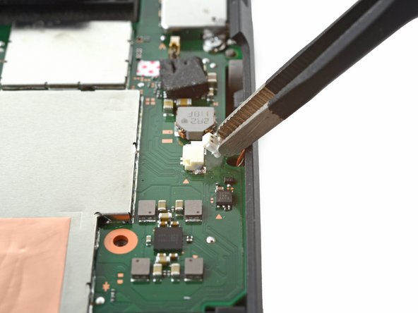
– Grab your trusty spudger and gently pop up the battery connector like you’re opening a treasure chest.
Tools Used
Step 25


– Grab some tweezers or use those nimble fingers to peel away the tape hiding the daughterboard’s screw.
Tools Used
Step 26


– Grab your Phillips driver and remove the 4mm screw that’s keeping the daughterboard attached to the frame.
Step 27


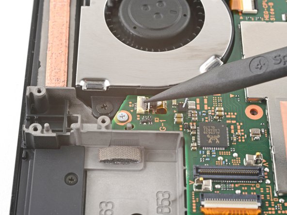
The daughterboard hooks up to the motherboard at the bottom with a snazzy press connector—easy peasy!
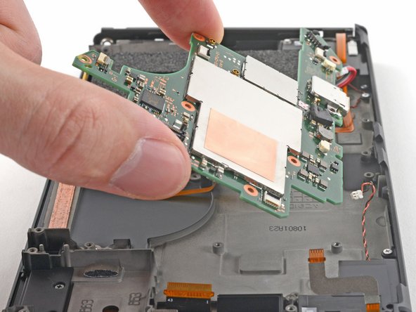
– Slide a spudger between the daughterboard and the motherboard like you’re slicing through digital butter.
– Gently pry up with the spudger to pop the press connector loose and free the daughterboard from its cozy frame.
– Lift out the daughterboard like the pro you are.
– When reconnecting press connectors like this one, line it up carefully and press down one side until it clicks, then do the same on the other side. Avoid pressing the middle—misalignment can bend the pins, and nobody wants that kind of drama!
Tools Used
Step 28


– Grab your trusty Phillips driver and unscrew those three 3 mm screws holding the heat sink to the motherboard. Easy peasy!
Step 29


You might encounter a little pushback here, and that’s totally okay! It’s just the heat sink getting cozy with the CPU thanks to some thermal paste. No worries!
– Slide a spudger gently between the heat sink bracket and the motherboard—it’s like separating old friends, no drama needed.
– Use the spudger to carefully pry up and lift the heat sink away from the motherboard. Nice and steady wins the day!
Tools Used
Step 30


– Slip a trusty spudger into the gap between the fan and the heat sink—it’s like a tiny pry bar, but cooler.
– Gently wiggle and pry up with the spudger to loosen the heat sink from the adhesive—it’s a bit sticky, but you’ve got this!
– Carefully lift and remove the heat sink. Bam! One less obstacle.
– Wipe off the old thermal paste from both the heat sink and CPU using some high-concentration (90% or higher) isopropyl alcohol and a microfiber cloth—it’s spa time for your components.
– Now, spread a fresh layer of thermal paste onto the CPU like frosting on a cake (but don’t eat it!) before putting things back together.
Tools Used
Step 31

– Grab a spudger, opening tool, or just your trusty fingernail, and gently pop up the tiny hinged flap on the fan cable’s ZIF connector—like you’re flipping open a secret compartment. Take your time, no rush, you’re doing great!
Tools Used
Step 32


– Grab a pair of tweezers and gently slide the fan cable straight out of its connector on the motherboard—nice and easy, like you’re unplugging a tiny little appliance.
Tools Used
Step 33

– Grab your trusty Phillips screwdriver and unscrew the three 3 mm screws holding the fan snugly onto the frame. You’ve got this!
Step 34


– Grab your trusty spudger and gently pop the fan straight out of its frame—nice and easy!
– Now, carefully take out the fan and set it aside. Boom, you’re making progress!
Tools Used
Step 35


– Grab an opening tool, spudger, or even your trusty fingernail, and carefully lift up the small, hinged locking flap on the power button board’s ZIF connector. Easy does it!
Tools Used
Step 36


– Grab your trusty tweezers and gently slide the power button board cable straight out from its connector on the motherboard. Easy does it!
Tools Used
Step 37


– Grab your trusty opening tool, spudger, or even just your fingernail, and gently pop up the small, hinged locking flap on the right Joy-Con sensor rail’s ZIF connector like a pro.
Tools Used
Step 38


– Gently grab a hold of the right Joy-Con sensor rail’s cable with a pair of tweezers and give it a smooth pull to disconnect it from its cozy spot in the motherboard’s connector.
Tools Used
Step 39


– Grab your trusty Phillips driver and get ready to tackle this! Remove those two 3.8 mm screws that are holding the left Joy-Con sensor rail snugly to the frame. You’re doing great!
Step 40

– Carefully detach the right Joy-Con sensor rail.
Step 41


– Grab your trusty opening tool, spudger, or even just your fingernail, and gently pop up the hinged locking flap on the display’s ZIF connector. Easy does it, you’re doing great!
Tools Used
Step 42


– Grab a pair of tweezers and gently unplug the display cable by pulling it straight out of its connector on the motherboard. Easy does it!
Tools Used
Step 43

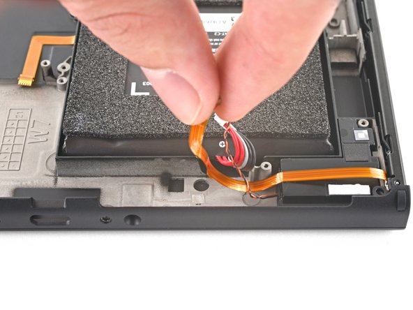
– Grab some tweezers or use your fingers and gently wiggle the left speaker’s JST connector out of its socket. You’ve got this!
Tools Used
Step 44

– Grab your tweezers—or just your fingers—and gently wiggle the right speaker’s JST connector free from its socket. Take your time, you’re doing great!
Tools Used
Step 45


– Grab your trusty opening tool, spudger, or even your fingernail, and carefully flip up that tiny, hinged locking flap on the ZIF connector for the right Joy-Con sensor rail. Take it slow and steady!
Tools Used
Step 46


– Grab your trusty tweezers and gently slide the right Joy-Con sensor rail’s cable straight out of its connector on the motherboard. Easy does it!
Tools Used
Step 47


– Grab your Phillips driver and remove those five screws holding the midframe to the frame:
– Three 3 mm screws
– Two 4.4 mm screws
Step 48

– Slide a spudger into the gap between the motherboard and the frame—like a pro sneaking a slice of cake.
– Gently pry upward with the spudger to free the motherboard from its snug little home.
– Carefully lift out the motherboard and set it aside like the treasure it is.
Tools Used
Step 49

– Gently lift the left Joy-Con sensor rail’s cable away from the frame using your fingers. Take it slow and steady, no need to rush!
Step 50

– Grab your trusty Phillips driver and unscrew the 3.8 mm screw holding the left Joy-Con sensor rail snugly to the frame. Easy peasy!
Step 51


– Pop off the left Joy-Con sensor rail.
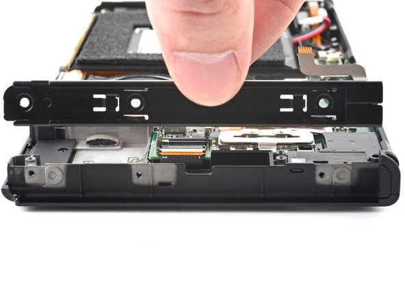
Step 52


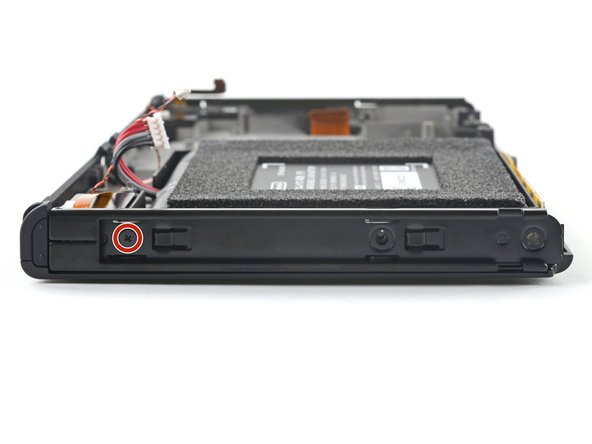
– Grab your trusty Phillips screwdriver and pop out those two 3 mm screws holding the bottom rail to the frame. Easy peasy, right?
Step 53
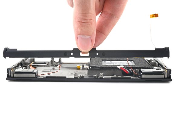

– Pop off that bottom rail like a pro. It’s easier than you think!
Step 54

– With a light touch, use your fingers to lift the power button’s cable away from the frame.
Step 55


– Gently wiggle the power button board out from its cozy little plastic slots in the frame.
– Remove the power button board.
Step 56

If you’re using adhesive remover, start off strong by following these prep steps first—it’s all about setting yourself up for success!
– Drip a little adhesive remover or some strong (90% or higher) isopropyl alcohol into the battery well along the top edge—it’s like giving the adhesive a chill pill to loosen it up.
Step 57

– Gently tilt the top edge of your device upward—give it a little lift—so the isopropyl alcohol can sneak its way under the battery and do its magic.
– Hold it like a pro for a solid 1-2 minutes, letting the isopropyl alcohol loosen up that stubborn adhesive.
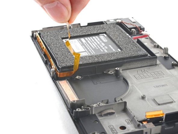
Step 58

Be careful when working with the battery – if you puncture or bend it, you’re risking a leak of some not-so-friendly chemicals or even a fire. Let’s keep things safe and fun!
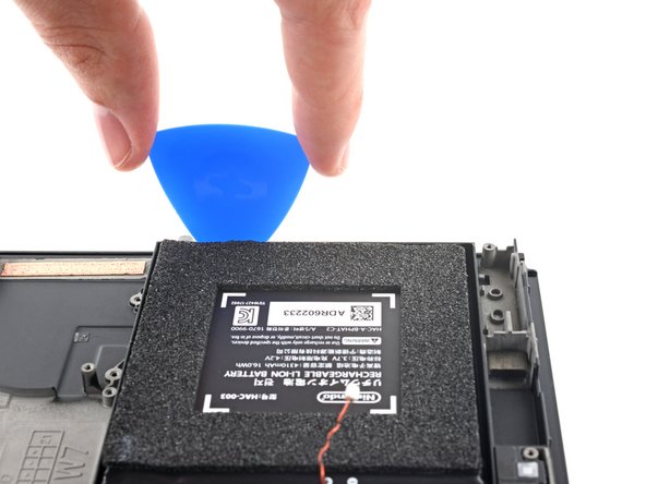
– Slip an opening pick into the gap between the battery and the side of the battery well—it’s like finding the perfect spot to wedge in!
– Gently work the tip of the pick under the battery and glide it along the edge, slicing through the adhesive as smoothly as spreading butter on toast.
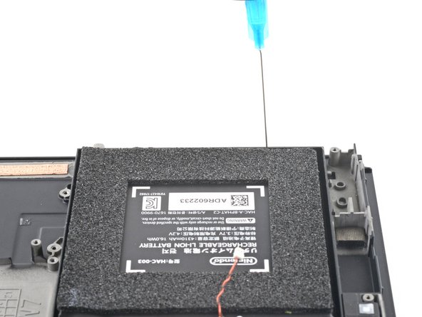
Step 59

– Keep that opening pick snug in place and splash in a few more drops of adhesive remover or isopropyl alcohol right inside the battery well. We want to loosen things up!
– Now, give the top edge of your device a gentle tilt upwards and hang tight for about 1-2 minutes while the isopropyl alcohol works its magic on the adhesive. Patience is key!
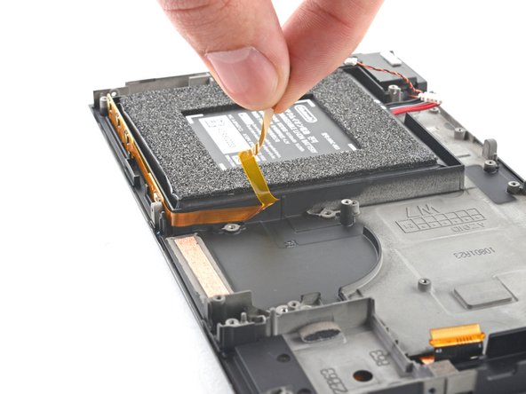
Step 60


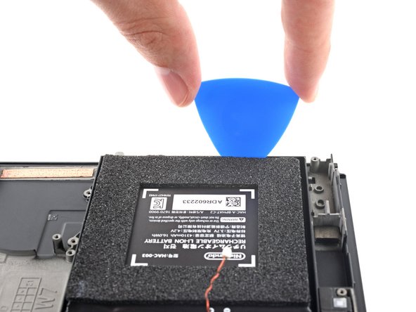
– Keep sliding that opening pick along the top edge of the battery, letting it glide deeper to slice through more of that pesky adhesive underneath.
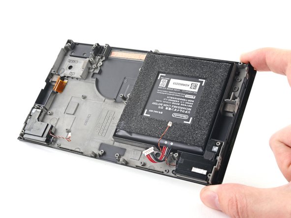
Step 61

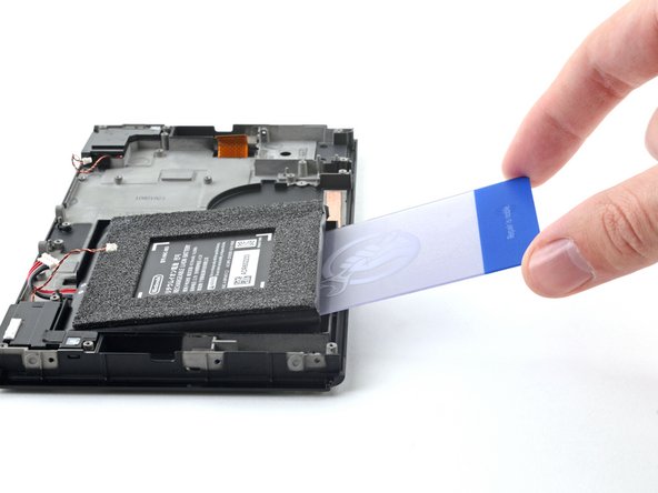
Handle that battery with care—no bending allowed while you’re prying it out!
If that stubborn piece isn’t budging, dab on a little extra isopropyl alcohol and give it another go.
– When you’ve got enough wiggle room, slip a plastic card under the battery and gently lift it out like a pro.
Step 62


Don’t even think about reusing that old battery – it’s time to give it a safe retirement! Swap it out with a shiny new one to keep your device running smoothly and safely.
Got a new battery without adhesive? No worries! Here’s how to stick some pre-cut adhesive onto the bottom of the battery like a pro.
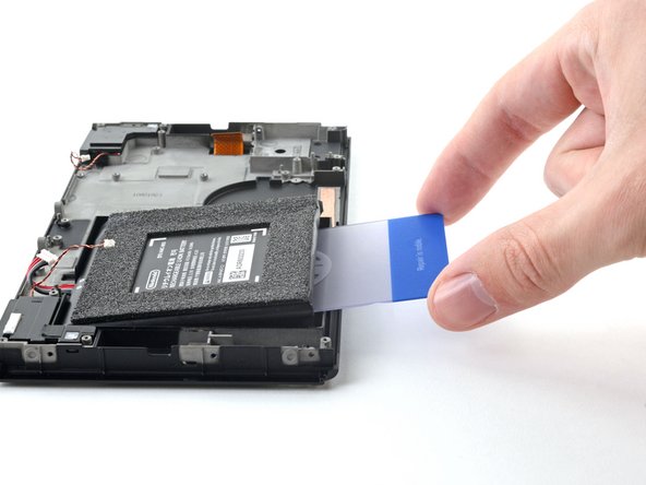
– Gently pry up with a trusty plastic card to free that pesky battery from its adhesive embrace.
– Carefully lift out the battery and bid it farewell.
– Grab some adhesive remover or a bit of isopropyl alcohol along with a microfiber cloth to wipe away any stubborn leftover adhesive in the battery well. Your new battery will appreciate the clean space!
Step 63

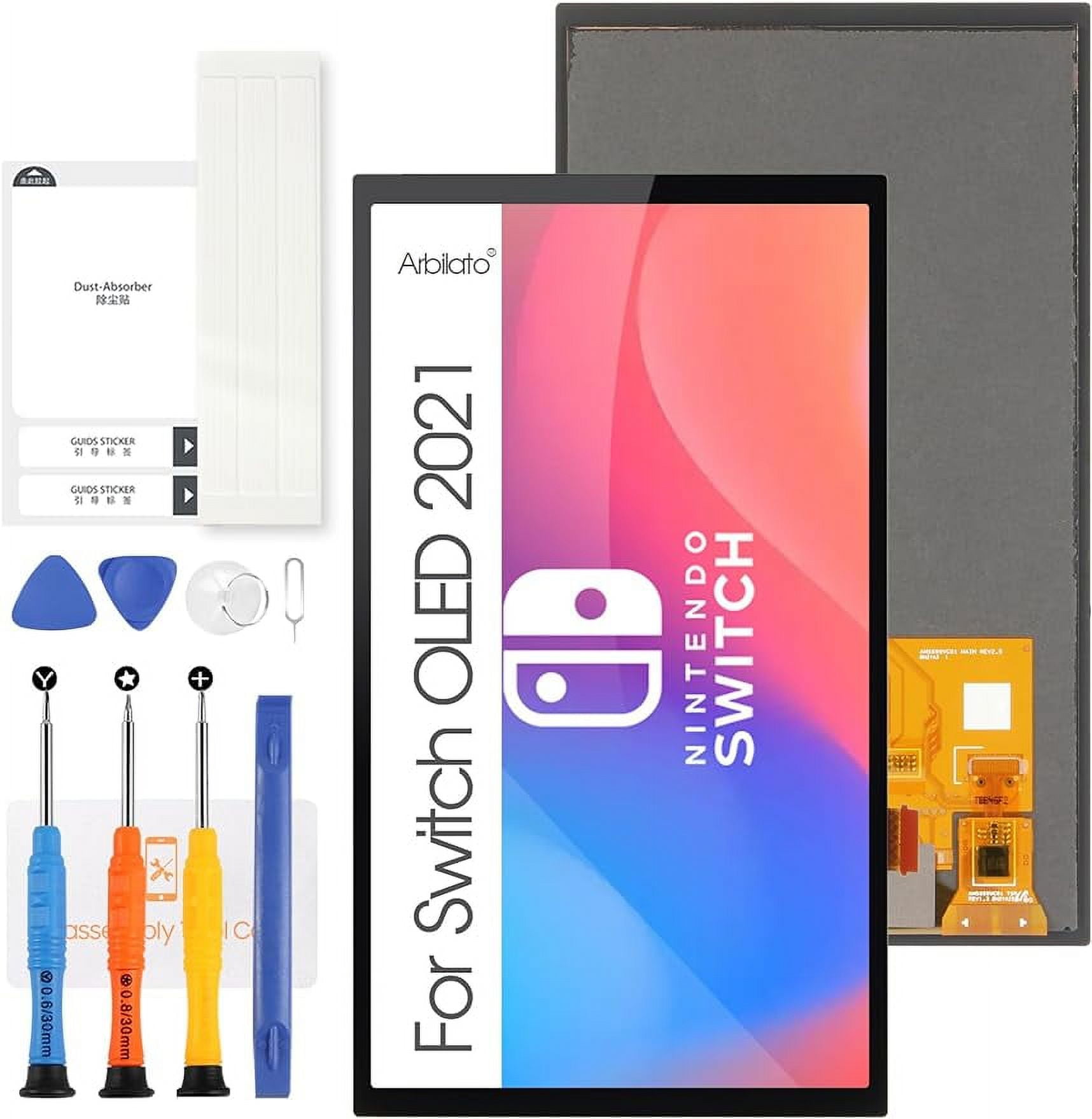
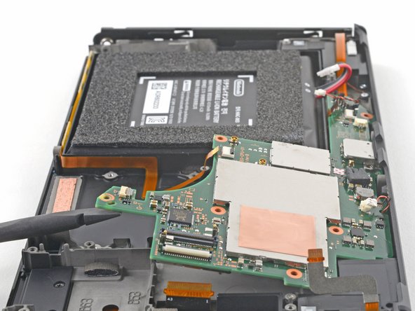
– Congratulations! You’ve successfully reached the Screen OLED Assembly stage.
Success!