How to Replace PlayStation 5 Optical Drive Laser DIY Guide
Duration: 45 minutes
Steps: 48 Steps
Shut it down and unplug all those pesky cables!
Get ready to tackle the task of swapping out the laser on your PlayStation 5! Before diving in, make sure to power down your console completely and unplug all those pesky cables. And hey, don’t forget to keep it safe by following those electrostatic discharge (ESD) safety tips while you work your magic!
Step 1

Make sure to work on a flat surface so your PlayStation stays put and doesn’t take a tumble.
If your PlayStation 5 is chilling in its horizontal vibe, feel free to skip ahead to Step 6.
– If your PlayStation 5 is standing tall like a champion, give it a little flip so the stand is waving at you from the top.
– Grab a coin or a flathead screwdriver and twist out that 26.5 mm-long stand screw like a pro!
Tools Used

Step 2


– Gently lift upwards to detach the stand.
Step 3


– Pop that screw into the little nook at the bottom of the stand.


Step 5


– Give that stand a gentle twist to the left and seal up the cubby. Need a hand? You can always schedule a repair.
Step 6


– Lay your PlayStation 5 face down with the charging port looking up if it’s in its horizontal mode.
– Pull the stand up straight and off it goes!
Step 7


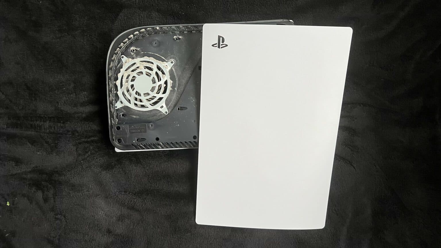
– Spin your device around so the USB and ethernet ports are chillin’ on the left side.
– Gently lift the corner of the faceplate to pop it off from the case.
Step 8


– Gently lift that corner up and slide the faceplate down towards the bottom of your device like a pro.
– Now, go ahead and remove that right faceplate with confidence!


Step 10


– Gently pry the grille away from the case to set it free.
Step 11

As you work on this repair, make sure to track each screw and return it to its original spot to keep your console safe and sound. If you need help, you can always schedule a repair.
– Grab your trusty TR8 Torx security driver and let’s get those four screws out of the fan shroud:
– Two screws, each 23.3 mm long
– One screw, 11.4 mm long
– And finally, one screw, a whopping 31 mm long


Step 13


Gently pry at the wire cover only—leave the fan wires alone, they’re not in the mood for any prying action!
– Slide the flat end of a spudger under the black wire cover and into the space above the fan wires.
– Use the spudger to gently lift the wire cover until you can grab it with your fingers.
Tools Used
Step 14


– Get ready to give that wire cover a new look – time to peel it off with your trusty fingers!
Step 15


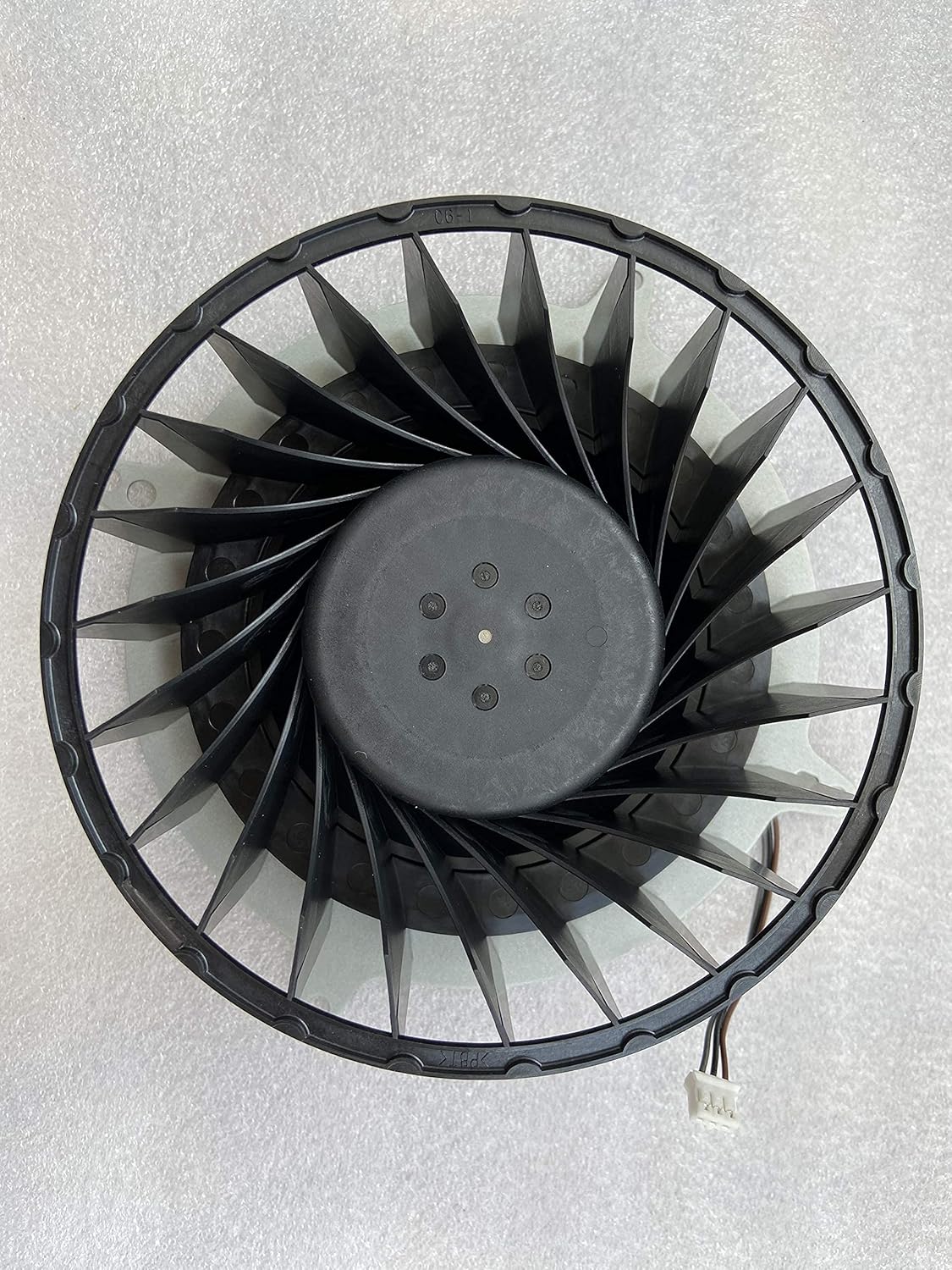
When handling cables, remember to always give the connectors the limelight and not the wires themselves!
– Gently grasp the edges of the fan cable connector with your fingers and give it a little tug upwards to disconnect it from the motherboard. You’ve got this!


Step 17

– Grab your trusty Phillips screwdriver and let’s tackle that 17 mm-long SSD cover screw like a pro!
Step 18


– Gently slide the SSD cover upward with your finger to release it from the case.
– Carefully remove the SSD cover.
Step 19


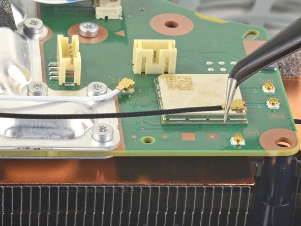
Remember, always unplug cables by grabbing the connectors—not the wires!
– Grab the edges of the optical drive cable connector with your fingers and gently pull it upwards to free it from the motherboard. You’ve got this!
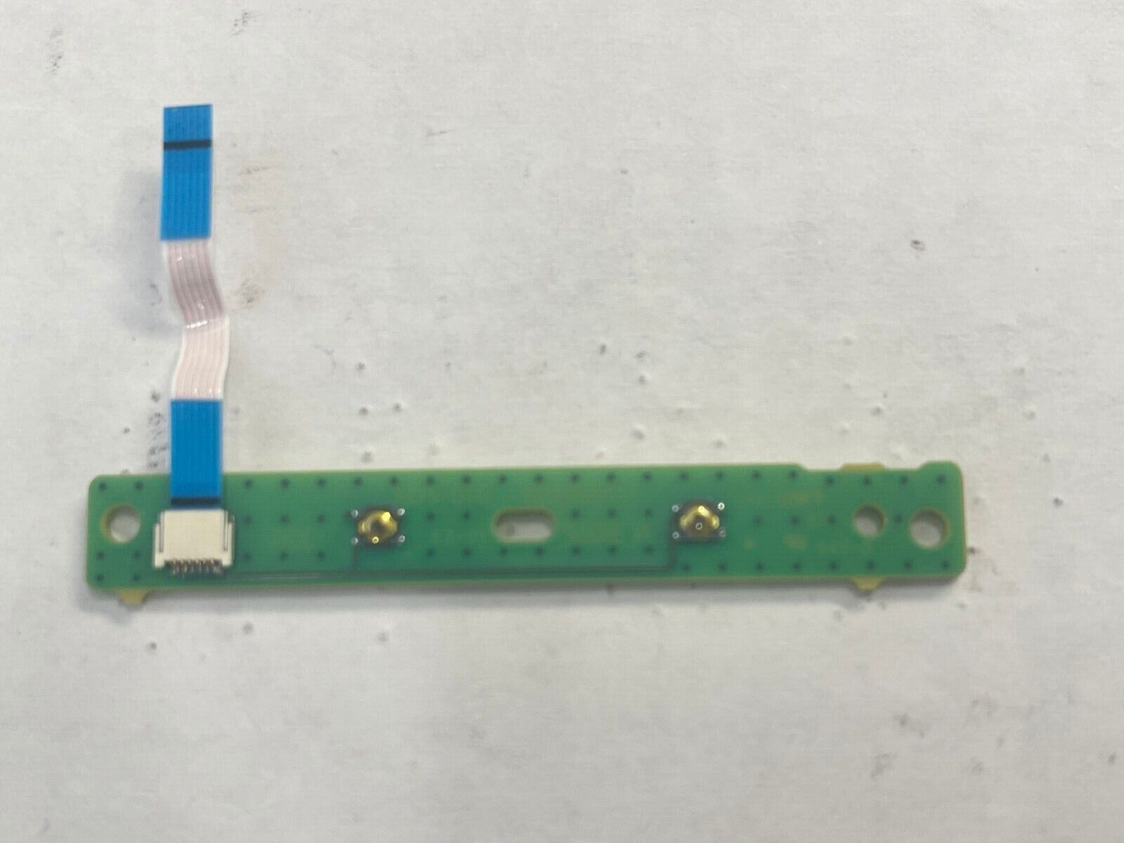
Step 20


– Just grab those edges of the optical drive cable connector with your fingers and give it a gentle pull to disconnect it from the optical drive. Easy peasy!
Step 21
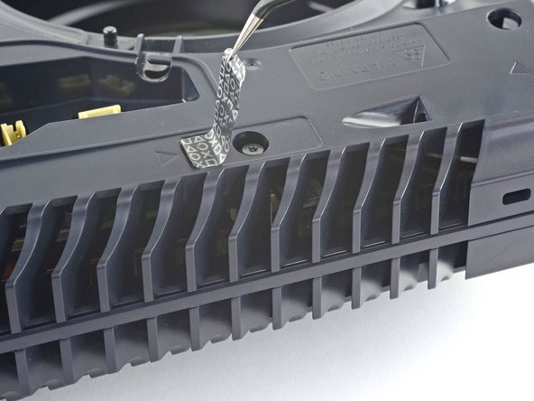

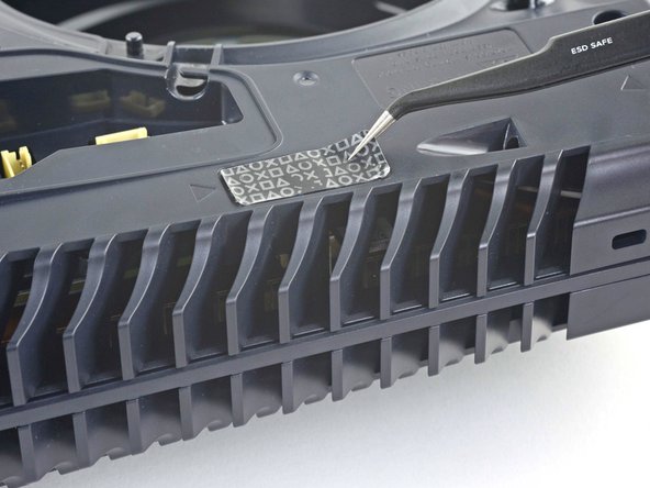
If your PlayStation 5 has never been opened before, the sticker will be solid black. Once you peel it off, you’ll see the fun pattern underneath!
These stickers are technically tamper-evident, but no worries—Sony can’t void your warranty as long as you keep everything intact. Enjoy the process!
– Grab a trusty pair of tweezers and gently peel away the tamper-evident sticker that’s hiding the last screw on the case. You’ve got this!
Tools Used
Step 22

– Grab your trusty T8 Torx driver and let’s get those eleven screws out of the case:
– Six screws that are 18.6 mm long, waiting to be freed.
– Two screws measuring 23.3 mm, just hanging out.
– Two longer screws at 43.2 mm, they’ve got some distance to cover.
– And don’t forget the little guy, a 7.3 mm screw, who’s ready to join the party!
Step 23


– Gently lift the case straight up to pop it off.
Step 24


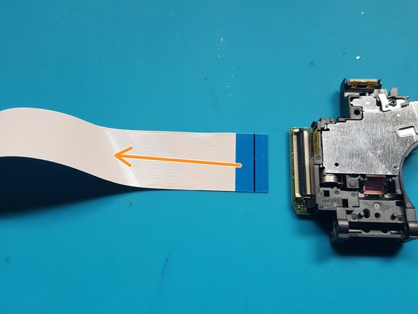
Gently tug on the pull tab, avoiding pulling on the cable directly.
– Grab your trusty spudger and gently press down on that shiny metal locking tab of the optical drive connector. You’ve got this!
– With the tab held down, take a pair of tweezers and confidently pull the blue pull tab straight out from the connector to disconnect the cable from the optical drive. Easy peasy!


Step 26

– Gather your silver screws: you’ll need 4 of those M1.6 X 3.7mm beauties with a 6.5mm head.
– Next up, grab 9 black screws, M1.6 x 3.8mm, for good measure.
– Now, it’s time to get to work! Use your trusty Phillips #1 screwdriver to remove those screws like a pro.
Tools Used

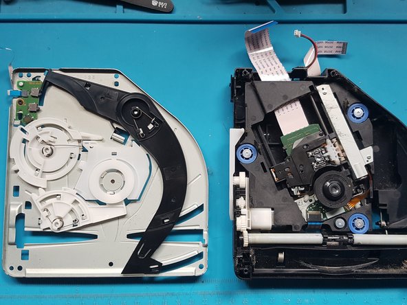
Step 27

– Pop off that top cover.
Step 28

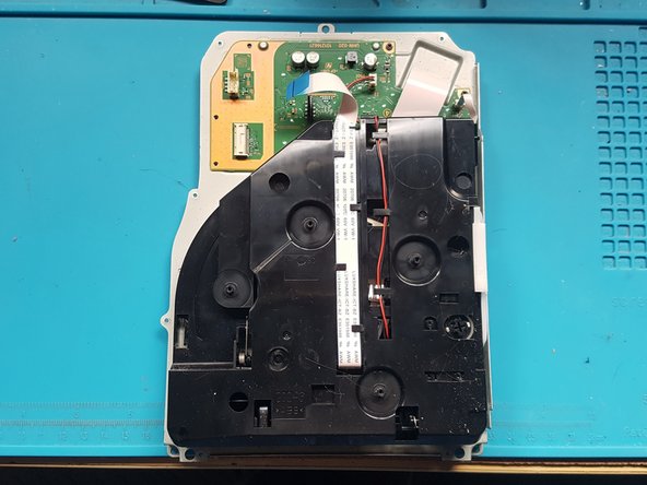
– Carefully pull out the medium and narrow FFC flexes and the 2-wire lead from their sockets. You can use some handy tweezers (either bent with points or with a straight blunt end) to help with the removal. If you need help, you can always schedule a repair.
Tools Used
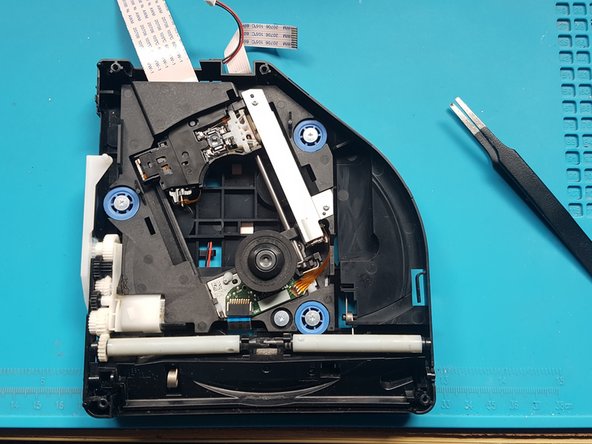
Step 29


– Time to get those screws out! Grab your trusty Phillips #1 screwdriver and let’s make it happen.
– Keep an eye out for those black screws: we need 2 of the M1.6 x 3.8mm variety. Let’s tackle this together!
Tools Used
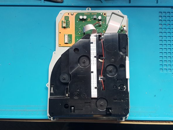
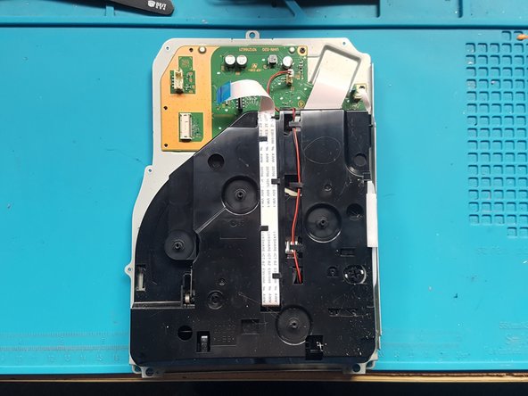
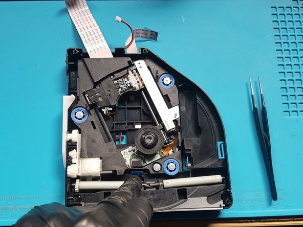
Step 30

– Gently lift the PCB and its attached assembly off the metal plate.
Step 31

– Flip the PCB and its attached assembly over.
Step 32

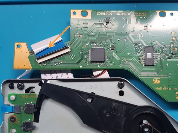
– Pop open that wide FFC socket with a gentle touch.
– Carefully lift the wide FFC cable out of the socket and set the PCB aside for now.
Step 33

– Turn the assembly over.
Step 34
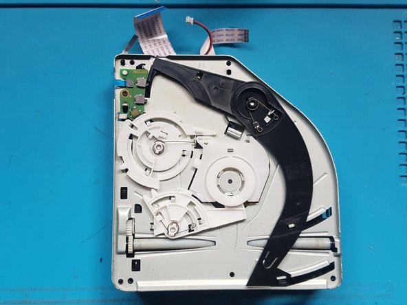

– Grab your trusty Phillips #1 screwdriver and get ready to unscrew those screws like a pro!
– You’ll be dealing with 4 sleek black screws: 4x M1.6 x 3.8mm. Let’s make it happen!
Tools Used
Step 35

– Gently remove the mechanism plate and set it aside.
Step 36

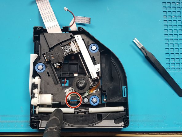
Grab those blunt-end straight tweezers to give you a hand in gently lifting out the FFC flex. Just pull the flex toward the rollers to pop it out of the socket. Easy peasy!
– Gently press down on the roller mechanism and carefully detach the FFC cable from the laser deck, which is located near the roller mechanism.
Tools Used
Step 37

Unscrew those pesky screws with a trusty Phillips #1 screwdriver! You’ve got this!
– Grab those shiny silver screws! You’ll need 4 of the M1.6 X 3.7mm variety with a 6.5mm head. Let’s get this repair party started!
Step 38

Alright, let’s roll up our sleeves and remove that laser deck!
Step 39

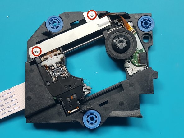
Time to get those screws out from the metal plate covering the laser motor! Let’s make some space.
Grab your trusty Phillips PH0 screwdriver and twist those screws loose. You’ve got this!
– Use the silver screws: 2x M1.7 X 3.8mm
Step 40

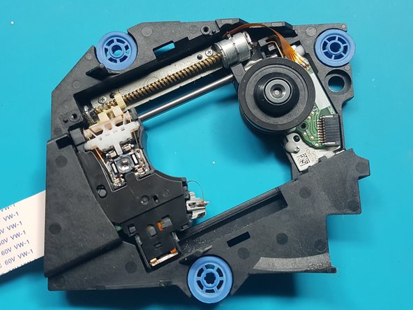
Time to uncover the laser motor by taking off that sleek metal plate.
Step 41

Let’s get that laser motor off the drive deck! Start by unscrewing those pesky screws that are holding it in place.
Grab your trusty Phillips PH0 screwdriver and twist those screws out like a pro!
– silver screws: 2x M1.7 X 3.8mm—grab ’em and let’s get screwin’!
Step 42


Heads up: The laser motor’s a bit wobbly, so handle with care when flipping over the deck for the next step.
Time to flip that device over and unscrew a single black screw from the white plastic bracket. You’ve got this!
Grab your trusty Phillips PH0 screwdriver and remove that screw like a pro.
Now, gently take off the white bracket and set it aside. You’re making great progress!
– black screw: 1x M1.4 x 3.9mm
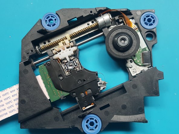
Step 43
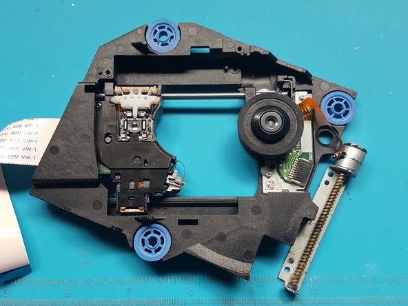

Flip the laser deck over and scoot the laser motor to the side
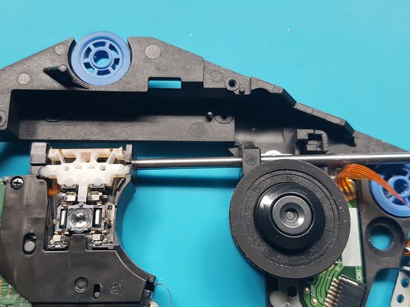
Step 44
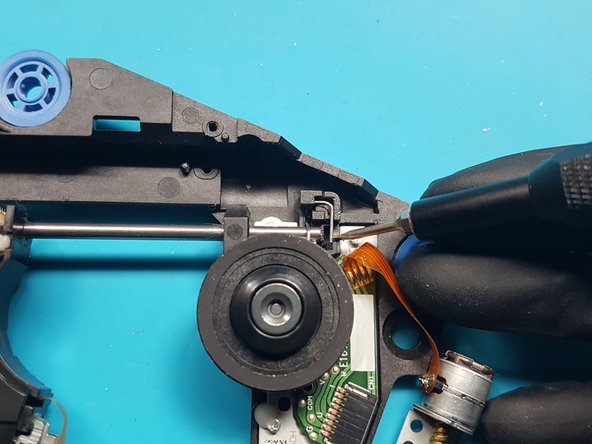
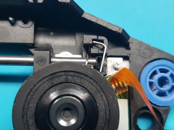

To kick things off, remove the clip that’s in the way of the rod’s freedom.
a) Grab a 1.5mm slotted screwdriver and nudge the lower part of the clip to the left, setting it free from the hook holding it back.
b) Watch as the clip makes its grand entrance by popping up.
c) With a touch of finesse, lift out the clip like a pro.
Step 45

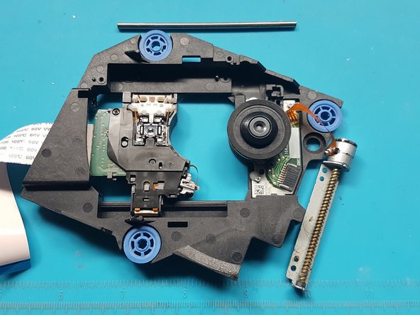
gently pull out the rod from the laser module.
Step 46
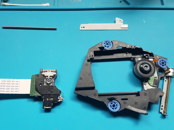

Take out the laser module.
Step 47
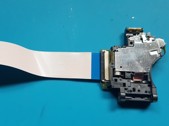

– Turn the laser module upside down.
Step 48

– Time to get that FFC connector unlatched! Let’s do this.
– Now, gently pull the FFC flex away from the laser. You’ve got this!