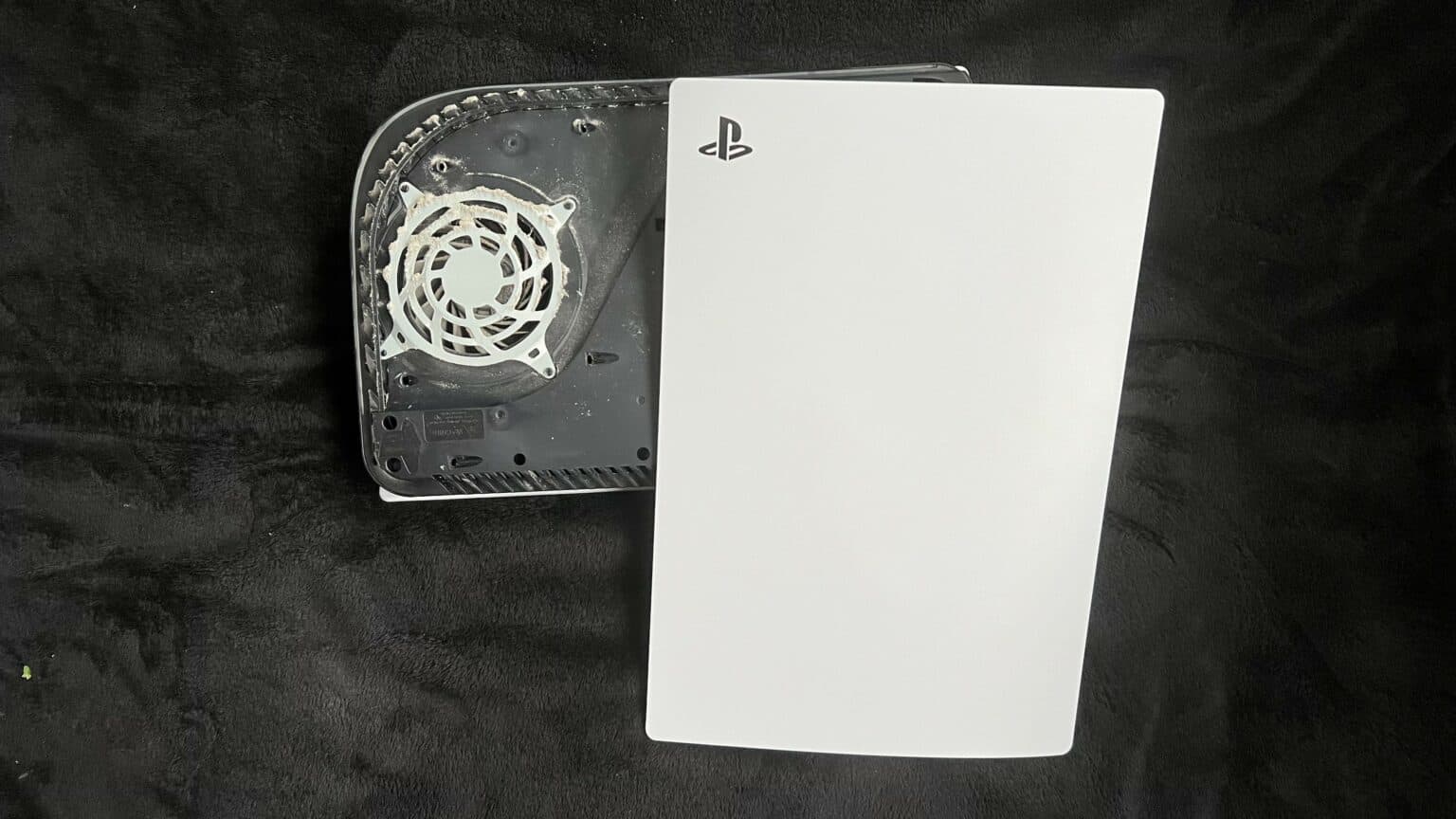
How To Replace PlayStation 5 USB Board Tutorial
Duration: 45 minutes
Steps: 43 Steps
Shut it down and unplug all those cords!
Ready to tackle that USB board replacement on your PlayStation 5? Awesome! Before you dive in, make sure to power down your console completely and unplug all those cables. And hey, don’t forget to practice some electrostatic discharge (ESD) safety while you’re at it. Let’s get to work!
Step 1

Keep it steady! Always work on a flat surface to stop your PlayStation from taking a dive.
If your PlayStation 5 is lying flat like a cozy cat, just jump on over to Step 6!
– Got your PlayStation 5 standing tall? Give it a little flip so the stand is facing the ceiling, like it’s ready to party!
– Now, grab a coin or a flathead screwdriver and let’s pop out that 26.5 mm-long stand screw. You’ve got this!
Step 2


– Gently lift straight up to free the stand.
Step 3


– Pop that screw right into the little cubby on the bottom of the stand like a pro!


Step 5


– Give the stand a little twist in the counterclockwise direction to snugly tuck away the cubby.
Step 6


– For the coolest look, place your PlayStation 5 horizontally with the charging port facing up.
– Easily pop off the stand by lifting it straight up – it’s as simple as that!
Step 7


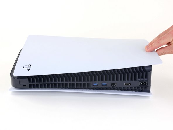
– Give your device a little twirl, revealing the USB and ethernet ports hanging out on the left side as if they’re ready to mingle.
– Gently lift up the corner of the faceplate, encouraging it to gracefully detach from the case.
Step 8


– Gently lift the corner and slide the faceplate down towards the bottom of your device.
– Now, go ahead and take off the right faceplate.


Step 10


– Gently lift the grille away from the case to set it free.
Step 11

While you’re working on this repair, make sure to track every single screw and return it to its original spot to avoid any mishaps with your console. If you need help, you can always schedule a repair.
– Get ready with your TR8 Torx security driver to tackle the four screws holding the fan shroud in place:
– Pair of 23.3 mm-long screws
– One 11.4 mm-long screw
– One 31 mm-long screw


Step 13


Carefully pry on the wire cover, and steer clear of the fan wires themselves. If you need help, you can always schedule a repair.
– Slide the flat end of your trusty spudger under the black wire cover and into the little gap right above those fan wires.
– Now, give that wire cover a gentle lift with the spudger until you can easily grab it with your fingers.
Tools Used
Step 14


– Get groovy and use your fingers to peel off the wire cover.
Step 15


Grab hold of those connectors, not the wires themselves, when pulling out cables. Be gentle, like a hug, and avoid any wire-tugging shenanigans. If you need a hand, feel free to schedule a repair.
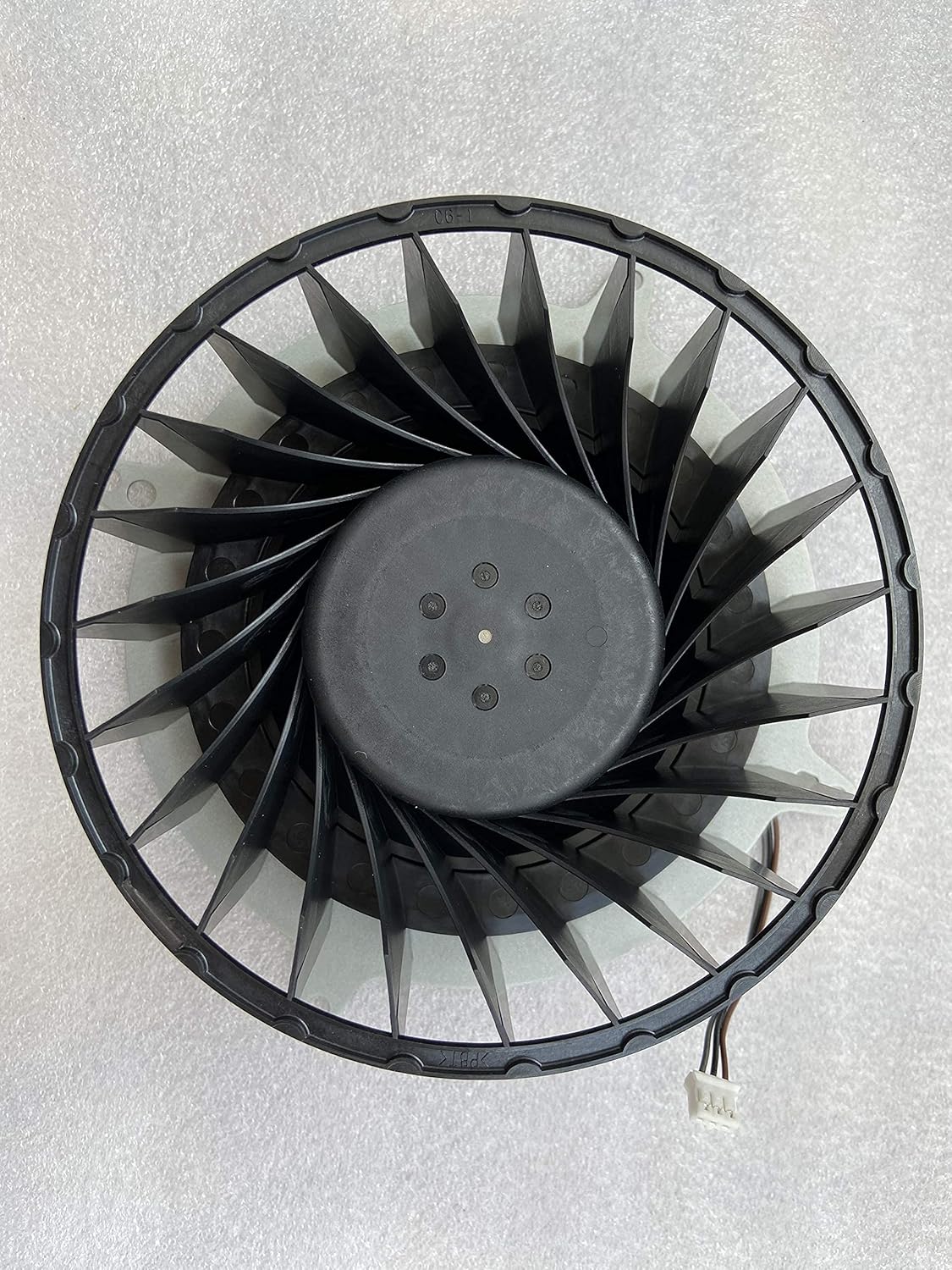
– Gently grasp the edges of the fan cable connector with your fingers, and give it a little pull upwards to disconnect it from the motherboard.


Step 17

– Grab your trusty Phillips screwdriver and take out that 17 mm-long screw holding the SSD cover in place. Let’s get that cover off!
Step 18


– Give that SSD cover a gentle nudge with your finger, sliding it up towards the top of the device to release it from its cozy home in the case.
– Now, go ahead and lift off the SSD cover. You’re doing great!
Step 19


When unplugging, always grab the connectors, not the wires. If you need help, you can always schedule a repair.
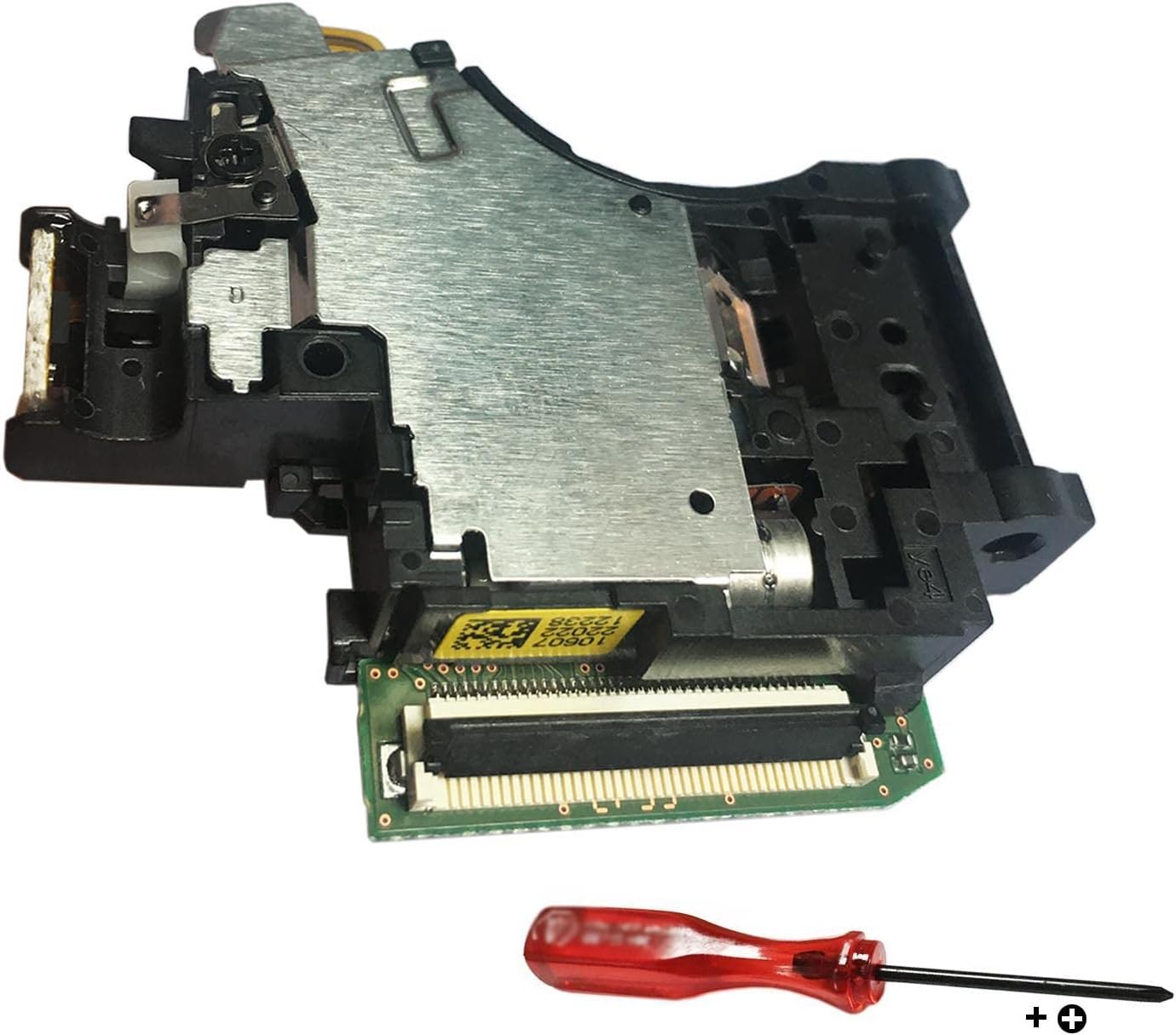
– Get a good grip on the edges of the optical drive cable connector with your fingers and give it a nice, firm pull to disconnect it from the motherboard. If you need help, you can always schedule a repair
Step 20


– Gently grasp the edges of the optical drive cable connector with your fingers and give it a little lift to disconnect it from the optical drive. You’ve got this!
Step 21
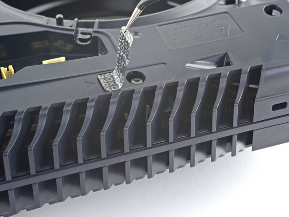

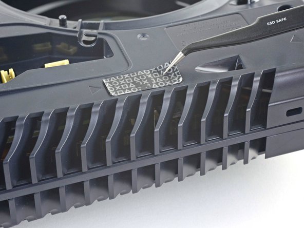
When you open a brand-new PlayStation 5, you’ll notice a solid black sticker. As you peel it away, a pattern will magically appear.
These stickers are here to show if someone’s tampered with the device—but relax—Sony can’t void your warranty just for removing it, as long as everything stays intact. Enjoy the journey!
– Grab a trusty pair of tweezers and gently peel away that tamper-evident sticker that’s hiding the last case screw. You’ve got this!
Tools Used
Step 22

– Grab your trusty T8 Torx driver and let’s tackle those eleven screws holding the case together:
– Six screws measuring 18.6 mm long
– Two screws that are 23.3 mm in length
– Two screws that stretch out to 43.2 mm
– And finally, one little screw that’s just 7.3 mm long.
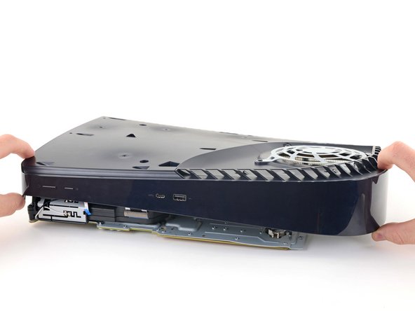
Step 23


– Gently lift the case straight up to set it free.
Step 24


Just tug on the tab, not the cable, okay?
– Grab the flat end of a spudger and press down on the optical drive connector’s metal locking tab.
– While holding the metal tab down, use tweezers to pull the blue pull tab straight out from the connector to disconnect the cable from the optical drive.


Step 26


– Grab your trusty spudger and use its flat end to gently press down on that sneaky metal locking tab of the optical drive connector.
– With the metal tab held down, take a pair of tweezers and carefully tug the blue pull tab straight out from the connector to disconnect the cable from the motherboard. Easy peasy!
Step 27


– Grab your trusty tweezers and give that blue pull tab a gentle tug, pulling it straight out from the connector. This will gracefully disconnect the power and eject button ribbon cable. You’ve got this!
Tools Used
Step 28


– Grab a trusty pair of tweezers and gently tug on that blue pull tab, pulling it straight away from the connector. This will disconnect the LED ribbon cable like a pro!
Tools Used
Step 29


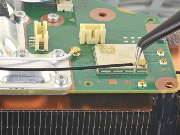
Some versions of the board might not have these antenna wires. If yours is missing these connectors, just skip ahead and keep rocking! If you need help, you can always schedule a repair.
– Grab a pair of tweezers and gently hold onto the white Wi-Fi antenna wire right at its metal base, getting as close to the connector as you can.
– Carefully lift the wire’s connector straight up to unplug it from the motherboard.
– Now, let’s do the same for the black Wi-Fi antenna wire. You’ve got this!
Tools Used
Step 30


– Grab your trusty tweezers and give a gentle squeeze to the black or blue power supply antenna wire right at its metal base, getting as close to the connector as you can.
– Now, with a steady hand, lift that connector straight up to free it from the motherboard.
– Don’t forget to do the same for the white power supply antenna wire!
Tools Used
Step 31


– Grab your trusty tweezers and gently lift the white sticker that’s keeping those antenna wires cozy on the top shield plate.
– Carefully detach the antenna wires from their sticker hideout.
– Give the white sticker a little love and press it back onto the top shield plate so it can be ready for reuse!
Tools Used
Step 32


– Follow the same process to peel back the remaining four stickers. Keep going, you’re doing great!
Step 33


– Grab a pair of tweezers and gently peel back the white sticker that’s keeping the LED ribbon cable cozy with the heat sink.
– Lift the LED ribbon cable from beneath the sticker, giving it the freedom it deserves.
– Give the white sticker a little pat on the back as you press it down onto the heat sink, ready for its next adventure.
Tools Used
Step 34

– Grab your trusty T8 Torx driver and let’s tackle those forty-two screws holding down the top shield plate:
– You’ll find forty-one screws that are 7.3 mm long, just waiting for you.
– And don’t forget the one special screw that’s 43.2 mm long!
Step 35


Make sure your new pads are just as thick as the old ones, or else the foam around the APU might not seal right. If you need help, you can always schedule a repair
– Carefully lift the top shield plate off the motherboard to set it free.
– As you put everything back together, it’s a great opportunity to swap out any thermal pads on the main board if they need a refresh. Those pads can sometimes stick to both the top shield plate and the main board, so watch out!
Step 36


– Gently press down on the metal locking tab on the USB board cable’s connector using your finger.
– With the metal tab pressed, use the flat end of a spudger against the foam pad on the ribbon cable and pull it away from the connector to disconnect it. If you need help, you can always schedule a repair.
Tools Used
Step 37
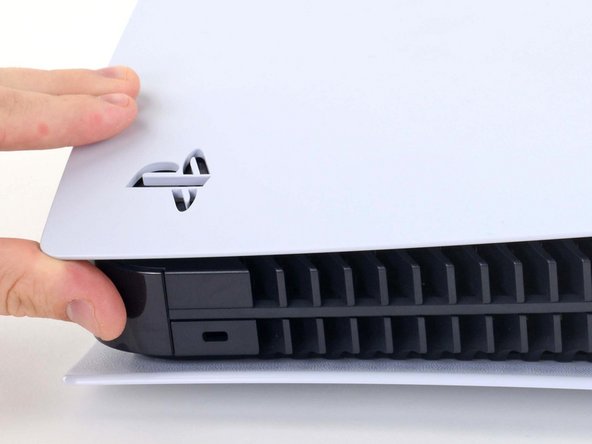

– Gently lift the corner of the faceplate featuring the PlayStation logo to pop it free from the case. Keep it cool and take your time—you’re doing great!
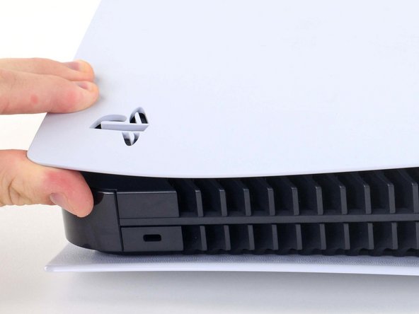
Step 38

– Gently lift the corner and slide that faceplate down towards the bottom of your device like it’s doing the cha-cha.
– Now, go ahead and take off the left faceplate with confidence!
Step 39

– Grab that Torx T8 driver and loosen up those two 29.4mm-long screws holding down the case to the motherboard and heat sink assembly.
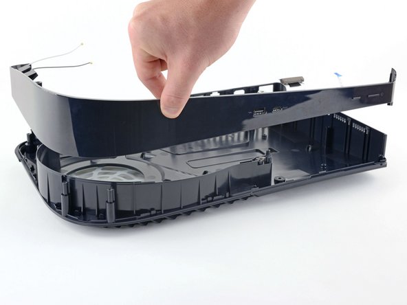
Step 40

– Lift the front edge of the case off the motherboard and heat sink assembly.
– With the front edge raised, push the case back away from the motherboard and heat sink assembly, guiding the charging port out of its slot.
– Remove the case.
– The front plate might come apart from the plastic case. When reassembling, make sure the front plate is in place before reinserting the motherboard and power supply.
Step 41

– Gently lift up to pop off the middle panel from the case.
Step 42

– Grab your trusty Phillips screwdriver and let’s get to work! Unscrew the three 6.5 mm-long screws holding the USB board in place. You’ve got this!
Step 43
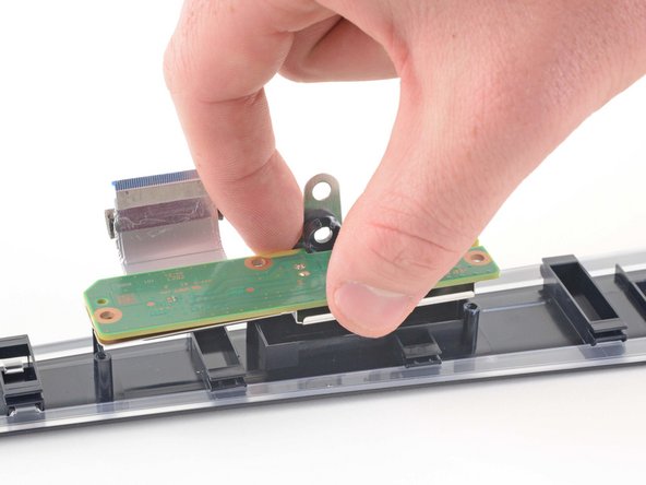
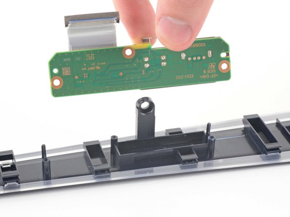

– Gently raise the USB board straight up to free it from the interactive band.