How to Replace Samsung Galaxy S20 Earpiece Speaker Tutorial
Duration: 45 minutes
Steps: 34 Steps
Hey there! Just a heads up, make sure to follow each step carefully to avoid any bumps in the road. And remember, if you need any assistance, feel free to schedule a repair. Happy repairing!
Alright, let’s dive in and tackle replacing the earpiece speaker in the Galaxy S20! Good news – you don’t absolutely have to take out the motherboard to get to the speaker, but trust me, it’s a smoother sail if you do. Make sure you have some extra adhesive handy to wrap up this little adventure!
Step 1


– Alrighty! Time to have some fun and bravely unlock your phone’s SIM tray compartment. Grab a handy SIM card eject tool, or maybe you’ve got a trusty paperclip that’s all ready for action? You know what to do – simply insert it into the teeny opening! Push and pop that baby right out, my friend! And if you need help, you can always schedule a repair.
Tools Used

Step 2


– Let’s kick things off by popping out the SIM card tray. Easy peasy!
– When you’re ready to put the SIM card back in, make sure it’s facing the right way to fit snugly in the tray. No one likes a misfit!
– Don’t forget about that nifty little rubber gasket around the SIM tray – it keeps water and dust at bay. If it looks worn out or is missing, it’s time to replace it. A new gasket or even a whole new SIM tray will help keep your phone’s insides safe and sound!
Step 3

Remember to give your phone a power nap by unplugging and powering it down before you get started!
– Warm up an iOpener and gently press it against the bottom edge of the back cover for about two minutes.
Tools Used

Step 4


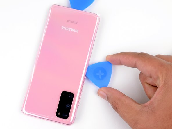
– Get your suction cup ready for action! Stick it on the back of the phone, aiming for the center of the bottom edge.
– Now for the fun part – give that suction cup a good pull, nice and strong. You’ll start to see a gap forming between the back cover and the frame. Exciting!
– Time to bring in the opening pick! Gently slide it into the gap you’ve created. Smooth and steady wins the race.
Step 5


– Gently slide the pick back and forth along the bottom edge to smoothly slice through that adhesive like a pro.
– Keep your opening pick in the seam to stop the adhesive from playing tricks and resealing.
Step 6

– Warm up the left edge of the back cover with a heated iOpener for two minutes to get things nice and cozy.
Tools Used
Step 7


Handle the pick with care—too much pressure could shatter that sleek back cover glass!
Don’t worry if it takes a few tries, these things can be a little picky.
– Grab a suction cup and stick it on the back of your phone, aiming for the center of the left edge – nice and snug!
– Now, give that suction cup a solid pull with some good, steady strength to open up a little gap between the back cover and the frame. You’ve got this!
– With that gap ready, slide the point of an opening pick right in there. It’s like giving your phone a tiny little hug to help it open up!
Step 8


– Once you’ve smoothly slid the pick under the glass’s edge, gently rock it downwards and slide it in a little deeper to completely free up the adhesive on the back cover.
Step 9


– Hey friend! Wanna make your phone or device look like new again? It’s piece of cake with these easy-peasy steps: First, slide that gadget guru tool smoothly down the side of your phone. Guess what? Leave that same handy-dandy tool under the edge at the top left, so the seal doesn’t fuss and muss. You’re all set to rock and roll! Remember, if you need a hand, our talented team at schedule a repair is here to help!
Step 10

– Warm up the right edge of the back cover with a heated iOpener for about two minutes. This will help make the adhesive a bit more forgiving, so you can get in there without a hitch!
Tools Used
Step 11


– Place a suction cup on the backside of your phone, aiming for the center of the right edge to get started.
– Give that suction cup a good, steady tug to open up a little gap between the back cover and the frame. You got this!
– Now, slide the tip of an opening pick into that gap you’ve created.
Step 12


– Alrighty, let’s keep those pickin’ fingers moving! Glide that tool along the side of your device, near where the exciting phone adventures happen. Don’t forget to give our glass some love near the top of your trusty companion, so it feels all secure and stuff. Wanna make sure the seal stays cracked and doesn’t try to mend itself. Now you’re on a rollercoaster ride of phone disassembling fun! If you ever need a hand, you can always schedule a repair and let our squad take over! 👍🔧
Step 13

– Warm up a heated iOpener and place it on the top edge of the back cover for a cozy two minutes.
Tools Used
Step 14


Hey there! Just a heads-up – the glass near the corners of the back cover is a bit delicate. Take it easy during this step to keep your back cover in tip-top shape!
– Gently glide the pick starting from the right side of your device, all the way around to the upper right corner.
– Keep moving smoothly along the top edge until you reach the top left corner to completely detach the back cover adhesive.
Step 15


– Gently lift the back cover, taking your time. If there’s any stubborn adhesive, use some opening picks to help you out.
– Carefully remove the back cover and set it aside.
– When putting everything back together:
Step 16

– Grab your trusty Phillips #00 screwdriver and get ready to unscrew! There are five 4 mm-long screws holding the motherboard bracket in place. Let’s take them out and move on to the next step!
Tools Used

Step 17


– Hey there! It’s time to unleash your inner tech hero and gently pry up those stubborn motherboard brackets with a trusty pair of tweezers. Unclip them from their friendly plastic home, and you’ll be one step closer to a fully functioning device! If you need help, you can always schedule a repair.
Tools Used

Step 18


– Carefully lift the wireless charging coil away from the device. You’ve got this!
– Take out the wireless charging coil like a pro.
– When putting everything back together, start by tightening the motherboard bracket screws to make sure the charging coil fits snugly. Then, give the rest of the coil a nice firm press down to get it to stick. You’re doing great!


Step 20

– Grab your trusty Phillips #00 screwdriver and say goodbye to those five 4 mm-long screws holding the loudspeaker and lower midframe in place.
Tools Used


Step 22

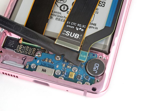
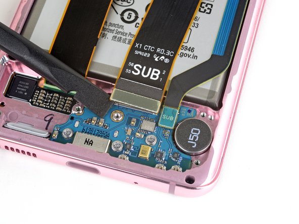
– Grab your trusty spudger and gently pry up those main and auxiliary flex cables from the daughterboard at the bottom of your device. You’ve got this!
– To reattach those connectors, just align them carefully and press down on one side until you hear that satisfying click. Then, do the same on the other side. Remember, no pressing down in the middle! If things get misaligned, you could bend those pins and that would be a real bummer. Stay cool and take your time!
Tools Used
Step 23

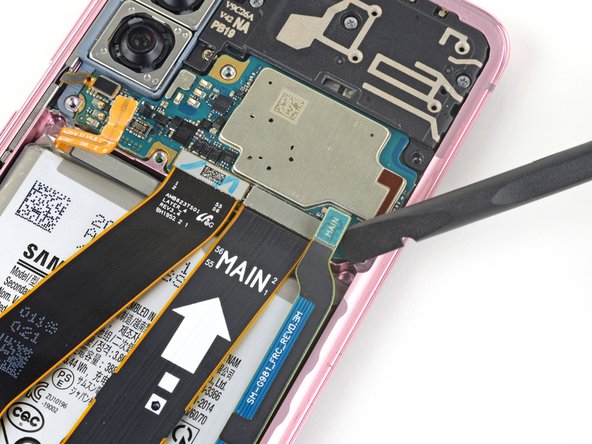

– Get ready to rock and roll by using a spudger to gently pop up and disconnect the main and auxiliary flex cables from the motherboard.
Tools Used


Step 25


– Time to bust out your trusty spudger! Gently pry up and disconnect the main display flex cable from the motherboard.
Tools Used
Step 26


– Hey buddy, bend with the times! Gently give that display flex cable some space and a dance, guiding it away from the motherboard and battery. You’ve got this! But if you need help, you can always
Step 27

– Grab your trusty Phillips #00 screwdriver and get ready to bid farewell to the four 4 mm-long screws holding the upper midframe in place!
– It’s time to show those screws who’s boss by gently removing them with your screwdriver.
Tools Used


Step 29


– Grab a spudger and gently nudge that side button flex cable away from the motherboard like you’re giving it a little high-five, disconnecting it with care.
– Now, take a pair of tweezers and give that cable a little bend to the side, creating some space for the motherboard to breathe.
Step 30


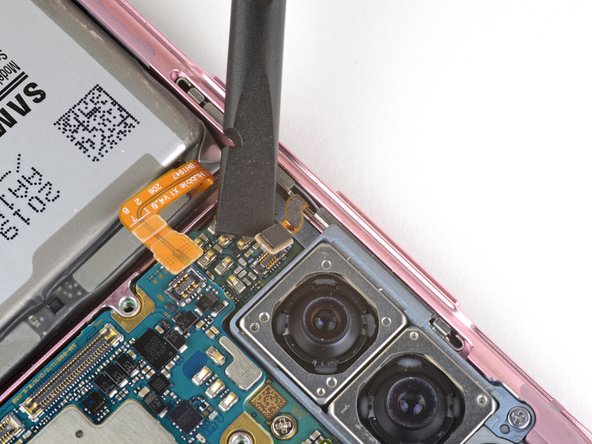
– Gently lift and detach the front-facing camera flex cable from the motherboard, just like peeling a sticker off a new gadget!
– Now, give that cable a little bend to keep it out of the motherboard’s way. It’s like creating a tiny space for it to chill!
Step 31

– Gently lift and detach the front-facing sensor array cable from the motherboard – it’s like giving it a little hug goodbye!
– Carefully bend the cable to keep it out of the motherboard’s way, just making sure it has some space to breathe.
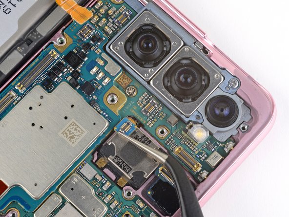
Step 32

– Grab your trusty Phillips #00 screwdriver and unscrew the two buddies holding together the motherboard and camera assembly.
Tools Used
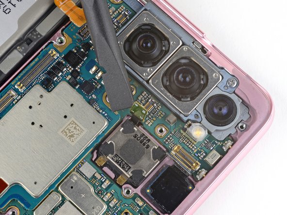
Step 33
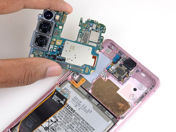

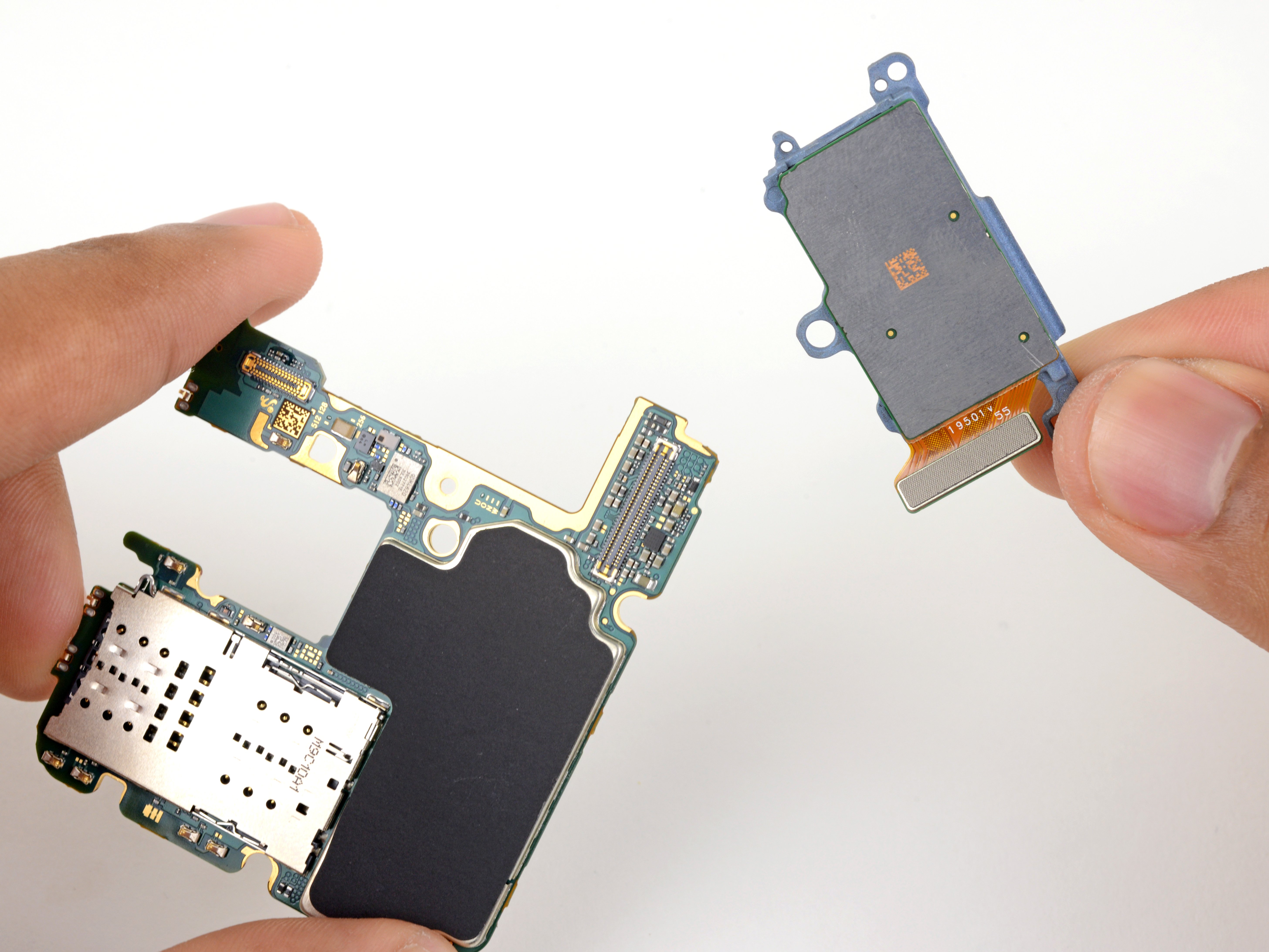
– Gently slide the flat end of your trusty spudger into the bottom left corner of the motherboard assembly and give it a little wiggle to pop it free from the phone body. You’ve got this!
– Now, carefully lift out the motherboard assembly and set it aside. You’re doing great!
Tools Used
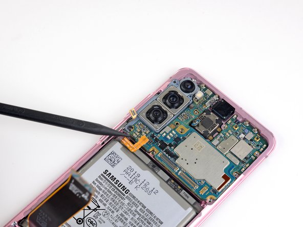
Step 34

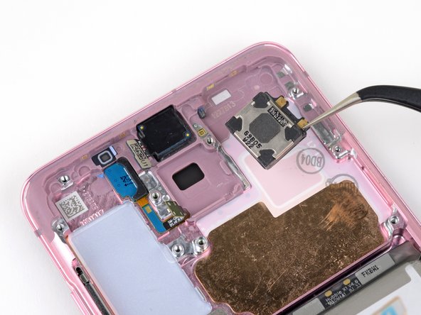
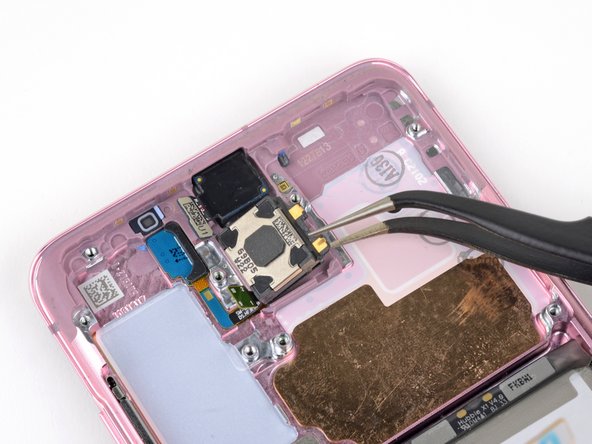
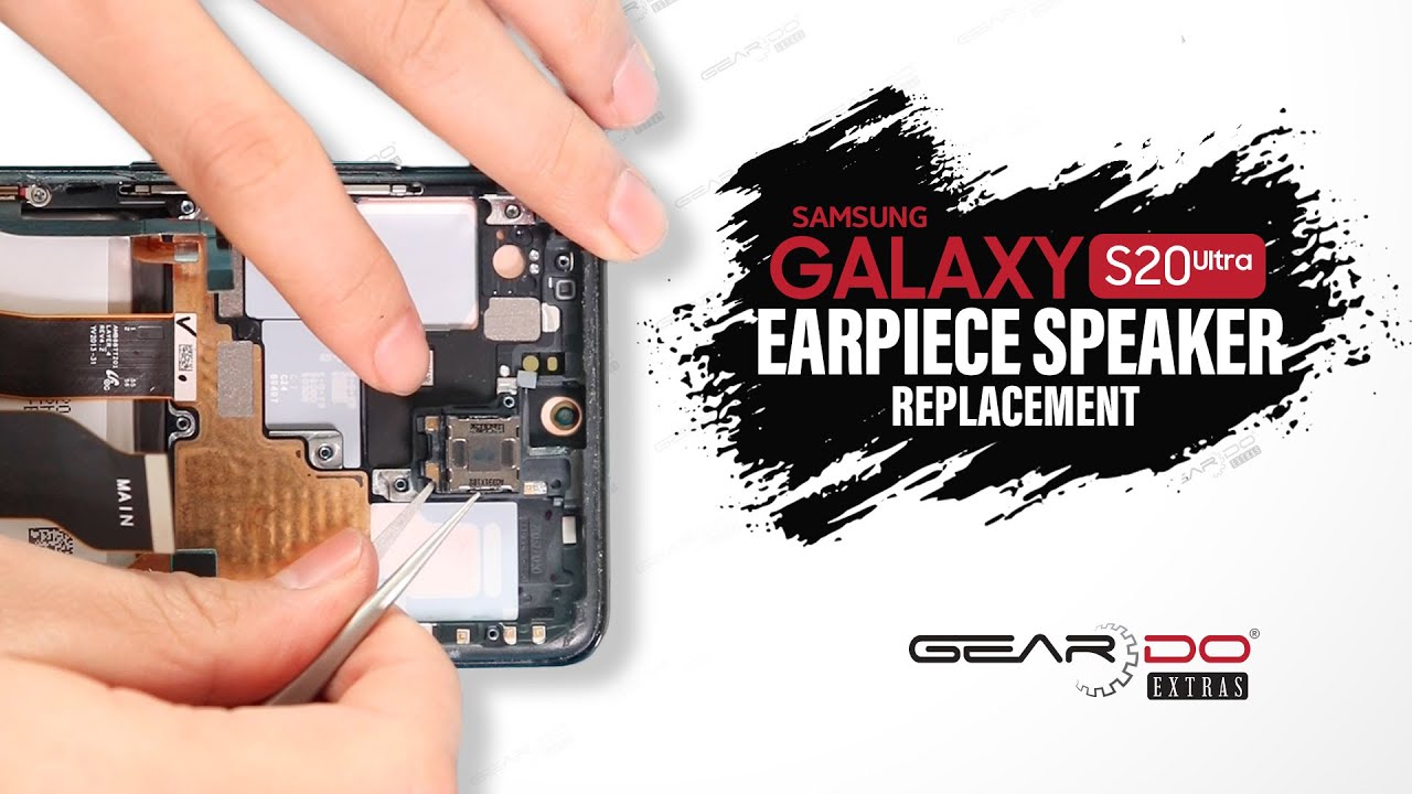
– Gently slide a point of a pair of tweezers into the cozy notch at the bottom right corner of the earpiece speaker.
– With a little finesse, carefully separate to free the adhesive and liberate the earpiece speaker.
– Feel free to keep the adhesive for later use when setting up a spanking new speaker, but if you’re in the mood for a change, go ahead and switch it out with a ready-to-go adhesive sheet.
Tools Used