How to Replace Samsung Galaxy S20+ Motherboard DIY Tutorial
Duration: 45 minutes
Steps: 42 Steps
Hey there! Just a quick heads-up: make sure to take your time and follow each step. If you hit a snag, don’t sweat it! If you need help, you can always schedule a repair. You’ve got this!
Get ready to tackle the challenge of swapping out the motherboard in your Galaxy S20 Plus! Just make sure you’ve got some fresh adhesive on hand to seal the deal. If you need help, you can always schedule a repair.
Step 1


– Grab a SIM card eject tool, a bit, or a trusty straightened paperclip and gently slide it into the tiny hole on the SIM tray at the top edge of your phone, right next to that snazzy plastic antenna band.
– Now, give it a good press to pop that tray out. You’re doing great!
Tools Used

Step 2


– First up, let’s kick things off by removing the SIM card tray. Easy peasy!
– When you’re ready to pop that SIM card back in, just make sure it’s sitting snugly in the right position in relation to the tray. No one likes a jammed SIM!
– Don’t forget, that rubber gasket around the SIM tray is like a cozy blanket for your phone, keeping out the pesky water and dust. If it’s looking worn out or has gone missing, it’s time to swap it out or grab a new SIM tray. Your phone’s inner workings will thank you!
Step 3

Go ahead and unplug your phone and power it down before diving in!
– Warm up an iOpener and let it chill on the bottom edge of the back cover for two minutes. You’ve got this!
Tools Used

Step 4


– Let’s start by gently placing a trusty suction cup on the back of your device, aiming for the center of the bottom edge.
– Now, with a bit of oomph, pull on the suction cup steadily to create some wiggle room between the back cover and the frame.
– Time to bring in the opening pick! Carefully slide its point into the gap you’ve created with the suction cup.
Step 5


– Gently glide the pick along the bottom edge, back and forth, to cut through that sticky adhesive like a pro.
– Keep your opening pick snugly in the seam to stop that adhesive from sealing up again. We’ve got this!
Step 6

– Warm up your iOpener and give it a cozy two-minute hug on the left edge of the back cover.
Tools Used
Step 7


With attention to detail, this may require a few tries.
– Start by sticking a suction cup onto the back of your phone, aiming for the center of the left edge—let’s get that thing open!
– Give that suction cup a firm, steady pull to make a little space between the back cover and the frame. You got this!
– Now, take the tip of an opening pick and gently slide it into the gap you created. We’re on our way!
Step 8


– Once the pick is snugly positioned beneath the edge of the glass, give it a little tilt downward and gently slide it in deeper to completely break the back cover’s adhesive seal. You’ve got this!
Step 9


– Gently glide the pick along the left edge of your device to separate the back cover’s adhesive.
– Keep your pick snug under the left edge of the glass to prevent the adhesive from sticking again.
Step 10

– Warm up your trusty iOpener and give the right edge of that back cover a cozy two-minute spa treatment.
Tools Used
Step 11


– Grab a suction cup and stick it right in the middle of the back of your phone, just a smidge away from the right edge.
– Give that suction cup a good, firm pull to open up a little space between the back cover and the frame.
– Slide the tip of an opening pick into that newly created gap and you’re on your way!
Step 12


– Let’s rock and roll that pick down the right edge of the phone like a pro! This will help us separate the back cover’s adhesive.
– Now, keep that bad boy under the right edge of the glass near the top of your device and avoid any adhesive annoyances.
Step 13

– Warm up the top edge of the back cover using a heated iOpener for a full two minutes.
Tools Used
Step 14


The glass at the corners of the back cover has a bit of a curve and can be prone to cracking. Take it easy during this step to keep your back cover safe and sound!
– Gently ease the pick into the right edge of your device and glide it around the top right corner like a pro.
– Keep on slicing along the top edge and continue all the way around to the left edge to completely break free the back cover adhesive.
Step 15


– Alrighty, let’s get that back cover gently lifted. Time for some pick-sliding action if there’s any stubborn adhesive left.
– Peel that back cover right off to greet its sunny day.
– Once the cover is history, remember during reassembly:
Step 16

– Grab your trusty Phillips #00 screwdriver and let’s get down to business! Carefully unscrew those six 4 mm screws that are holding the motherboard bracket into place. You’ve got this!
Tools Used

Step 17


– Grab a trusty pair of tweezers and carefully lift up that motherboard bracket from the plastic midframe. You’ve got this!
Tools Used

Step 18


– Carefully lift the motherboard bracket upwards to reveal the orange battery connector waiting for your attention.


Step 20


– Grab your trusty spudger and gently pry up to disconnect that wireless charging coil connector. You’ve got this!
Tools Used
Step 21


– Alrighty, folks, it’s time to tackle that tricky wireless charging coil! Worry not, ’cause we’ve got all the intel you need to ace this repair. First things first, grub those tweezers, ’cause you’re gonna gently peel that coil away from the device. Then, wave a fond goodbye to that coil. Once you’re ready to ace that reassembly, you’ll want to connect those charging coil and battery connectors, give those motherboard bracket screws a snug refit, and then really solidify that coil pad bond to get it stickin’ to your device! Wanna get this done lickety-split but need a hand? No worries – you can always schedule a repair!
Tools Used
Step 22

– Grab your trusty Phillips #00 screwdriver and let’s get to work! Remove the five screws, each measuring 4 mm, that are holding down the loudspeaker and lower midframe. You’ve got this!
Tools Used
Step 23


– Grab your trusty spudger or a pair of tweezers, and gently slide the tip into the notch located at the top left corner of the midframe. Give it a little pry to pop those clips loose and set the midframe free!
– Now, let’s make some space by removing the loudspeaker and the lower midframe. You’re doing great!
Step 24


– Grab your trusty spudger and gently pry up those main and auxiliary flex cables from the daughterboard at the bottom of your device. You’ve got this!
– To reconnect those connectors, simply align them carefully and press down on one side until you hear that satisfying click! Then do the same on the other side—just avoid pressing in the middle. If things seem a bit off, don’t worry; a little care goes a long way to prevent bending those pins and causing permanent damage.
Tools Used
Step 25


– Grab your trusty spudger and gently lift up those main and auxiliary flex cables from the motherboard. You’ve got this!
Tools Used


Step 28


– Get your trusty spudger and gently pry up the main display flex cable from the motherboard to disconnect it.
Tools Used
Step 29


– Gently lift and nudge the display along with the left 5G antenna flex cables to the side, making some room for the motherboard and battery to breathe.
Step 30

– Grab your trusty Phillips #00 screwdriver and gently unscrew those three 4 mm-long screws holding the upper midframe in place. You’ve got this!
Tools Used


Step 32


– Get your spudger ready to gently pry up and disconnect the right 5G antenna flex cable from the motherboard.
– Now, it’s time for some precision work – use a pair of tweezers to delicately bend the cable out of the way, giving your motherboard some breathing room.
Step 33


– Gently pop up and unplug the side button flex cable from the motherboard.
– Move the cable aside to keep it clear of the motherboard.
Step 34


– Gently pry up and disconnect the front facing camera flex cable from the motherboard.
– Carefully bend the cable out of the way of the motherboard.
Step 35


– Pop off the upper 5G antenna cable from the motherboard. If you need help, you can always schedule a repair
Step 36


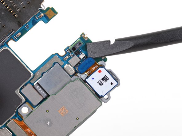
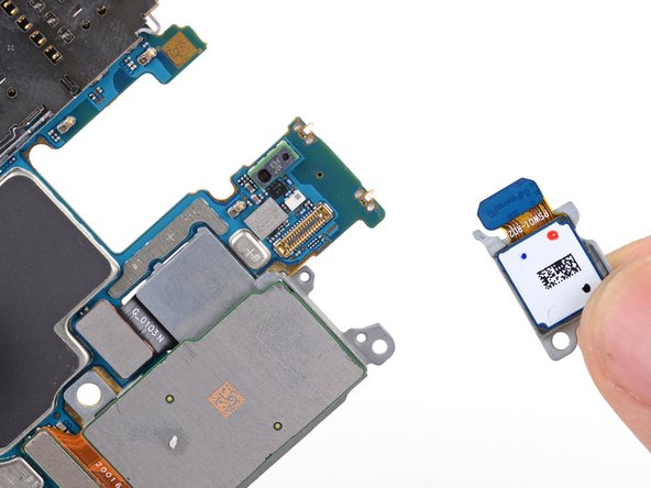
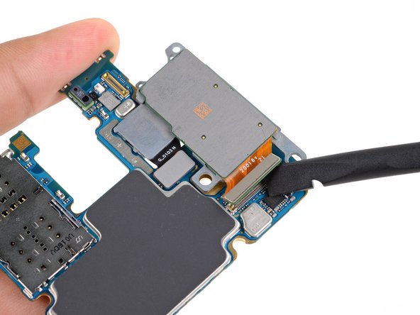
– Grab that trusty spudger and carefully lift up the corner of the 5G millimeter wave antenna module.
– Gently remove the 5G antenna module.
– When putting it all back together, make sure to reconnect the 5G antenna connector first to align it properly, then press down the rest of the antenna module to secure it. If you need help, you can always schedule a repair.
Tools Used
Step 37

– Grab a trusty Phillips #00 screwdriver and start by unscrewing the two little screws holding down the motherboard and camera assembly. Piece of cake!
Tools Used
Step 38


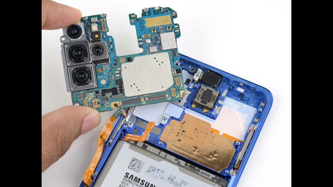
– Gently slide the flat end of a spudger into the bottom left corner of the motherboard assembly and lift up to set it free from the phone body.
– Now, lovingly remove the motherboard assembly.
Tools Used
Step 39

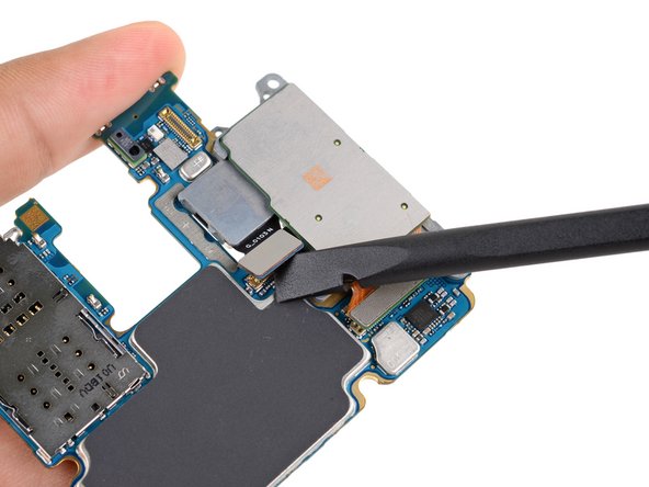
– Grab the flat end of a spudger to pop up and unplug the ultrawide camera connector from the motherboard.
– Take out the ultrawide camera module.
Tools Used
Step 40

– Grab your trusty spudger and gently lift to disconnect the telephoto and wide-angle camera connectors from the motherboard.
– Carefully lift and unplug the depth sensor. If you need help, you can always schedule a repair
Tools Used
Step 41

– Take out the last rear-facing camera module with a smile! If you need help, you can always schedule a repair.


