How to Replace Samsung Galaxy S20 Rear Facing Camera Module Guide
Duration: 45 minutes
Steps: 35 Steps
Heads up! Before diving into this repair, make sure you’re in a comfy space where you can spread out your tools and get your fix on. Remember, if the going gets tough, you can always schedule a repair!
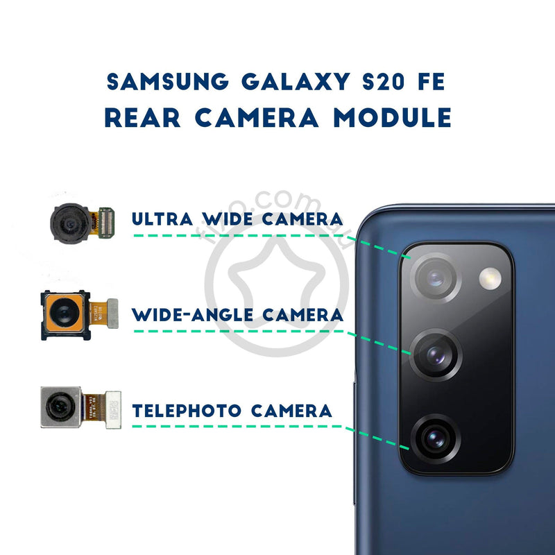
Get ready to swap out the rear-facing camera module on your Galaxy S20! This little assembly is made up of two parts and houses all three rear-facing cameras, along with the frame that keeps them snug. Just a heads up, you’ll need to take out the motherboard to get to it. Don’t forget to grab some replacement adhesive to wrap things up nicely. If you need help, you can always schedule a repair.
Step 1


– Time to get that SIM card tray out! Grab your trusty SIM card eject tool, a small screwdriver, or even a straightened paperclip, and gently insert it into the tiny hole on the SIM tray at the top edge of your phone, right next to the plastic antenna band.
– Now, give it a firm press to pop that tray out. You’ve got this!
Tools Used

Step 2


– Let’s start by popping out the SIM card tray. Easy peasy!
– When you’re ready to slide that SIM card back in, make sure it’s facing the right way to fit snugly in the tray.
– Remember, there’s a little rubber gasket hugging the SIM tray that keeps out water and dust. If you spot any damage or if it’s missing, it’s a good idea to swap it out or get a whole new SIM tray. This will help keep your phone’s insides safe and sound!
Step 3

Don’t forget to give your device a little nap by unplugging and turning it off before we dive in!
– Warm up an iOpener and press it against the bottom edge of the back cover for two minutes. Let’s get that cover nice and cozy!
Tools Used

Step 4


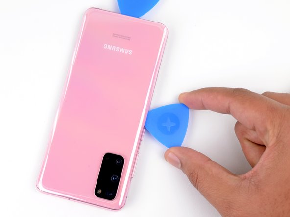
– To kick things off, grab a trusty suction cup and apply it lovingly to the back of your device, aiming for the sweet spot at the center of the bottom edge.
– Next, channel your inner superhero and give that suction cup a good, firm tug to create a magical gap between the back cover and the frame.
– Now, it’s time to slide in the pointy end of an opening pick into the gap and work your magic.
Step 5


– Gently glide your pick along the bottom edge, wiggling it side to side to break through that sticky adhesive.
– Once you’ve made some progress, tuck your opening pick into the seam to keep that adhesive from getting all clingy again.
Step 6

– Warm up the left edge of the back cover with a heated iOpener for a solid two minutes. It’s like giving your device a cozy little spa day!
Tools Used
Step 7


Be gentle with the pick—too much pressure and you might end up with a cracked back cover glass. Let’s keep it safe and sound!
Don’t worry if it takes a few tries; precision is key!
– No worries! Let’s make this phone rescue party a fun adventure. Give that prime suction cup spot a gentle hug near the center of the left edge, then unleash your inner superhero with a strong and steady tug to create a secret entrance! Now, slide that sneaky opening pick into the secret passage and let the magical repair begin. If you need help, you can always schedule a repair!
Step 8


– Once you slip that pick under the glass’s edge, give it a little tilt down and slide it in a bit more to completely free up the adhesive holding the back cover in place.
Step 9


– Alrighty, let’s slide our cool pick along the left edge of your phone, as if it’s a dance move. And remember, keep the pick under the left edge near the top-left corner, so the adhesive doesn’t sneak back in all sly-like!
Step 10

– Warm up that trusty iOpener and give the right edge of the back cover a cozy two-minute hug.
Tools Used
Step 11


– Stick a suction cup on the back of your phone, aiming for a spot near the center on the right edge—like a pro!
– Give that suction cup a nice, firm pull to open up a little gap between the back cover and the frame. You’ve got this!
– Slide the tip of an opening pick into that gap you just created. Let’s get this party started!
Step 12


– Gently glide your pick along the right edge of the phone to break free the back cover’s sticky grip.
– Keep that pick nestled under the right edge of the glass, just near the top, to stop the adhesive from making any sneaky comebacks.
Step 13

– Get your iOpener nice and toasty, then gently place it on the top edge of the back cover for a cool two minutes.
Tools Used
Step 14


The glass around the corners of the back cover is a bit wobbly and has a knack for cracking. So, let’s take it easy during this step to keep your back cover safe and sound!
– Gently glide the pick from the right edge of your device and around the top right corner like you’re wrapping a cozy blanket.
– Keep on slicing along the top edge all the way to the top left corner to fully free the back cover from its adhesive hug.
Step 15


– Gently lift the back cover like you’re unveiling a surprise! Use those opening picks to carefully cut through any stubborn adhesive that might be holding on.
– Take off the back cover and let it breathe!
– As you put everything back together:
Step 16

– Grab your trusty Phillips #00 screwdriver and gently take out the five 4 mm-long screws that are keeping that motherboard bracket snug as a bug. You’re just a few twists away from opening up a whole new world of repair possibilities!
Tools Used

Step 17


– Grab your trusty tweezers and give the motherboard bracket a gentle tug to unclip it from the plastic midframe. You’ve got this!
Tools Used

Step 18


– Carefully lift the wireless charging coil away from the device like you’re peeling a banana—gentle does it!
– Now, go ahead and take out the wireless charging coil. It’s time for it to take a break!
– When you’re putting everything back together, make sure to fasten those motherboard bracket screws first. It’ll help you align the charging coil perfectly. Once that’s done, give the rest of the coil a nice firm press to stick it down right.


Step 20

– Grab your trusty Phillips #00 screwdriver and let’s tackle those five 4 mm-long screws that are holding the loudspeaker and lower midframe in place. You’ve got this!
Tools Used


Step 22

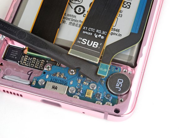
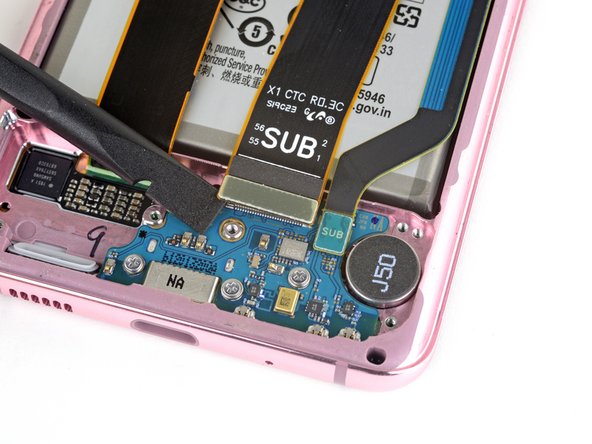
– Grab your trusty spudger and gently wiggle those main and auxiliary flex cables free from the daughterboard at the bottom of your device. You’ve got this!
– When it’s time to re-attach those connectors, take a moment to carefully line them up. Press down on one side until you hear that satisfying click, then do the same on the other side. Just a friendly reminder: avoid pressing down in the middle! Misalignment can bend those little pins and lead to some serious trouble. If you need help, you can always schedule a repair.
Tools Used
Step 23

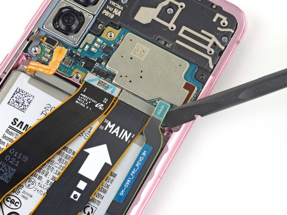

– Let’s get groovy and use a spudger to gently lift and disconnect the main and auxiliary flex cables from the motherboard.
Tools Used


Step 25


– Grab your trusty spudger and gently pry up to disconnect the main display flex cable from the motherboard. You’ve got this!
Tools Used
Step 26


– Carefully lift and bend the display flex cable to clear the way for the motherboard and battery. You’ve got this!
Step 27

– Grab your trusty Phillips #00 screwdriver and carefully unscrew the four 4 mm-long screws that are holding the upper midframe in place. You’ve got this!
Tools Used


Step 29


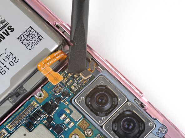
– Get your spudger ready to rock and roll as you gently pry up and disconnect the side button flex cable from the motherboard.
– Grab those tweezers and do a little dance as you deftly bend the cable out of the way of the motherboard.
Step 30


– Gently pry up and disconnect the front facing camera flex cable from the motherboard.
– Simply bend the cable out of the way of the motherboard.
Step 31

– Gently pop up and unplug the front-facing sensor array cable from the motherboard. You’ve got this!
– Carefully bend the cable to keep it out of the motherboard’s way. Easy peasy!
Step 32

– Grab your trusty Phillips #00 screwdriver and gently unscrew the two little screws holding the motherboard and camera assembly in place. You’ve got this!
Tools Used
Step 33
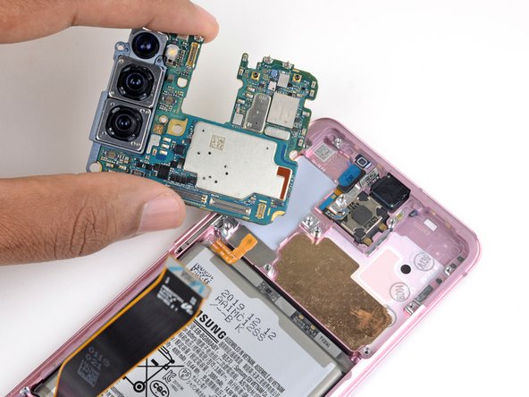
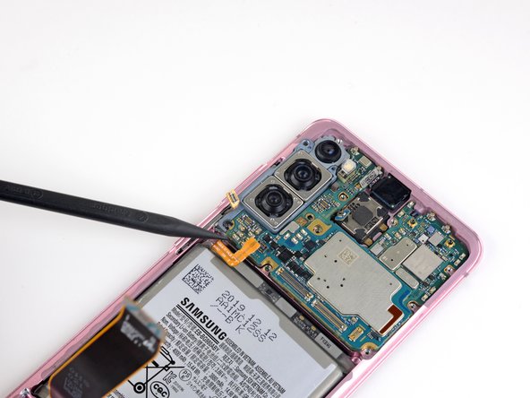

– Gently slide the flat end of your trusty spudger into the bottom left corner of the motherboard assembly and give it a little pry to pop it free from the phone body. You’ve got this!
– Now, go ahead and lift out the motherboard assembly with care.
Tools Used
Step 34

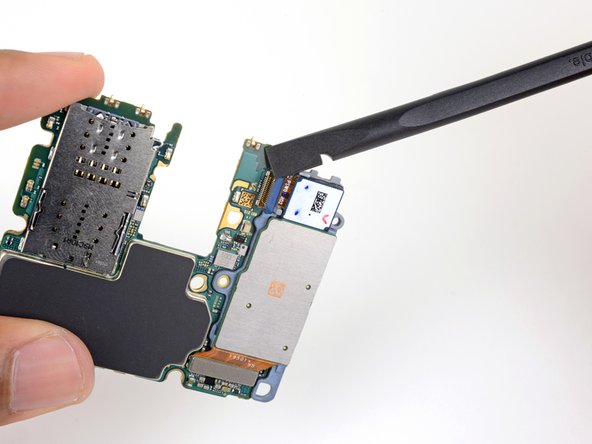
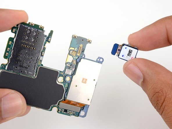
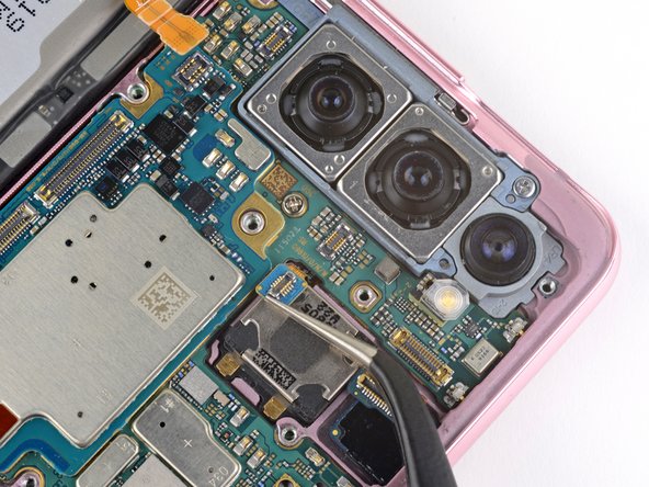
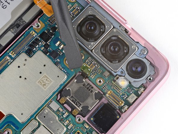
– Grab your trusty spudger and gently pry up the ultrawide camera connector from the motherboard. It’s like giving it a little hug to disconnect it!
– Now, go ahead and remove the ultrawide camera module. You’ve got this!
Tools Used
Step 35

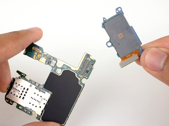
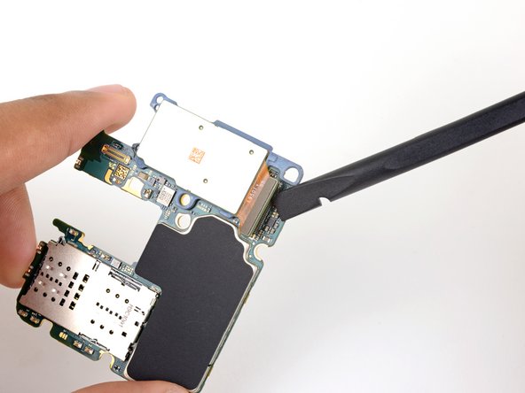
– Grab a spudger and gently lift up the telephoto and wide-angle camera connectors from the motherboard with a little hug.
– Wave goodbye to the last rear facing camera module as you carefully remove it.
Tools Used