How to Replace Samsung Galaxy S20+ Rear Facing Camera Module Step-by-Step Tutorial
Duration: 45 minutes
Steps: 41 Steps
Hey there, buddy! Don’t worry if you run into any snags while fixing your device – we’ve all been there. Just give our friendly techies a shout if you need a hand schedule a repair!
Let’s dive into the fun of swapping out the rear-facing camera module for your Galaxy S20 Plus! This nifty module consists of two parts and houses all four of those awesome rear-facing cameras, along with the frame that keeps them snugly in place. Just a heads up, you’ll need to take out the motherboard for this little adventure. Don’t forget to grab some replacement adhesive to seal the deal at the end. And if you run into any bumps along the way, remember, you can always schedule a repair!
Step 1


– Got a SIM card eject tool, a bit, or even a straightened paperclip? Perfect! Time to show that SIM tray who’s boss. Locate it at the top edge of your device, right next to the plastic antenna band.
– Give it a good, firm press to pop that tray right out.
Tools Used

Step 2


– Get that SIM card tray out of there, time to give it a break.
– When the SIM card goes back in, make sure it’s facing the right way in its cozy tray.
– Oh, and don’t forget about that fancy rubber gasket circling the SIM tray for protection against water and dust. If it’s not looking its best, swap it out or go all out and replace the entire tray to safeguard your phone’s insides.
Step 3

Make sure to unplug and power down your phone before diving in!
– Warm up your iOpener and gently press it against the bottom edge of the back cover for a cozy two minutes.
Tools Used

Step 4


– Get that suction cup ready! Stick it to the back of your phone, aim for the center at the bottom – you’ve got this!
– Give that suction cup a good pull with some oomph, create some space between the back cover and the frame – easy does it!
– Time to get that opening pick into the gap, sneak it in like a boss!
Step 5


– Gently glide your pick back and forth along the bottom edge to cut through that pesky adhesive.
– Keep your opening pick nestled in the seam to stop the adhesive from sealing up again.
Step 6

– Heat things up a bit by applying a warm iOpener to the left edge of the back cover for a cozy two minutes.
Tools Used
Step 7


No worries if it takes a few tries, these things happen!
– Stick a suction cup on the back of the phone, targeting the center of the left edge for maximum effect.
– Give that suction cup a good tug with a steady hand to create some wiggle room between the back cover and the main body.
– Slide an opening pick into the little gap you’ve made to get things started.
Step 8


– Once your trusty pick is nestled under the edge of the glass, give it a gentle tilt downward and slide it in a bit more to completely break free that stubborn back cover adhesive.
Step 9


– Gently glide your pick along the left edge of the phone to break that stubborn adhesive holding the back cover in place.
– Keep your pick snugly under the left edge of the glass to stop that adhesive from getting all clingy again.
Step 10

– Get your heated iOpener ready and give the right edge of the back cover some love for a solid two minutes.
Tools Used
Step 11


– To get started, apply a trusty ol’ suction cup right smack dab in the middle of the right edge of your device.
– Give that suction cup a good, solid yank to create a space between the back cover and the frame. You got this!
– Now, take a spiffy opening pick and slide it into the gap you just made. Piece of cake!
Step 12


– Gently slide the pick along the right edge of the phone to work its magic in separating the back cover’s adhesive.
– Don’t forget to tuck your trusty pick under the right edge of the glass near the top of the device to keep that adhesive from pulling any funny business and resealing on you.
Step 13

– Get cozy with a heated iOpener and lay it gently on the top edge of the back cover for a two-minute heat session.
Tools Used
Step 14


The glass around the corners of the back cover has a little curve to it and can be a bit fragile. So, take it easy during this step to keep your back cover safe and sound!
– Gently glide the pick from the right side of your device toward the upper right corner.
– Keep on smoothly cutting along the top side until you reach the left edge to fully detach the adhesive holding the back cover.
Step 15


– Gently lift off the back cover, taking your time. Use those trusty opening picks to cut through any stubborn adhesive that might be holding on.
– Now, go ahead and remove that back cover completely!
– When it’s time to put everything back together:
Step 16

– Grab your trusty Phillips #00 screwdriver and get ready to work some magic! Unscrew those six 4 mm-long screws that are holding your motherboard bracket in place. You’re doing great!
Tools Used

Step 17


– Gently coax the motherboard bracket out of its cozy spot in the plastic midframe using a trusty pair of tweezers.
Tools Used

Step 18


– Carefully lift the motherboard bracket just enough to reveal the orange battery connector waiting for its moment to shine.


Step 20


– Grab your trusty spudger and gently pry up to disconnect that wireless charging coil connector. You’ve got this!
Tools Used
Step 21


– Grab a trusty pair of tweezers and carefully peel back the wireless charging coil from the device. Take it slow—no need to rush this part!
– Once you’ve gently lifted it away, it’s time to remove the wireless charging coil completely. You’re almost there!
– As you put everything back together, make sure to reconnect the charging coil and battery connectors first. Then, refasten those motherboard bracket screws to keep everything snug. Finally, give the coil pad a firm press so it sticks nice and tight. You’re doing great!
Tools Used
Step 22

– Grab a Phillips #00 screwdriver to gently bid farewell to five 4 mm-long screws that are holding hands with the loudspeaker and lower midframe.
Tools Used
Step 23


Step 24


– Grab a spudger and gently wiggle it to lift up and disconnect the main and auxiliary flex cables from the daughterboard located near the bottom of your device. You’re doing great!
– When it’s time to reconnect those connectors, just align them carefully and press down on one side until you hear that satisfying click. Then, do the same on the other side—just a little bit of love there! Remember, keep your fingers off the middle to avoid bending those delicate pins. If they get misaligned, it could lead to some serious trouble.
Tools Used
Step 25


– Grab your trusty spudger and gently wiggle it to lift and disconnect the main and auxiliary flex cables from the motherboard. You’re doing great!
Tools Used


Step 27


– Gently lift and disconnect the left 5G antenna cable from the motherboard. You’ve got this!
Step 28


– Grab a spudger and gently work your magic to lift up and disconnect the main display flex cable from the motherboard. You’ve got this!
Tools Used
Step 29


– Carefully lift and flex the display along with the left 5G antenna cables, making sure they’re out of the way of the motherboard and battery. You’ve got this!
Step 30

– Grab your trusty Phillips #00 screwdriver and casually take out those three 4 mm-long screws holding the upper midframe in place.
Tools Used


Step 32


– Get your spudger ready to work its magic! Gently pry up and disconnect the right 5G antenna flex cable from the motherboard.
– Time to show some finesse! Grab your trusty pair of tweezers and carefully bend the cable out of the way of the motherboard.
Step 33


– Gently lift and disconnect the side button flex cable from its motherboard home.
– Sway the cable aside, making space for the motherboard to breathe.
Step 34


– Gently lift and detach the front-facing camera flex cable from the motherboard. You got this!
– Carefully bend the cable out of the way so it doesn’t interfere with the motherboard. Keep it safe!
Step 35


– Gently lift and disconnect the upper 5G antenna cable from the motherboard. You’ve got this!
Step 36


– Grab your trusty spudger and delicately lift the corner of the 5G millimeter wave antenna module.
– Bid farewell to the 5G antenna module.
– When putting things back together, start by reuniting the 5G antenna connector to ensure a perfect match, then give the rest of the antenna module a good ol’ press to stick it back in place.
Tools Used
Step 37

– Grab your trusty Phillips #00 screwdriver and go ahead and unscrew those two little screws holding the motherboard and camera assembly in place. You’re almost there!
Tools Used
Step 38


– Gently slide the flat side of your spudger into the cozy little nook at the bottom left corner of the motherboard assembly. Give it a little pry to set it free from the phone’s embrace.
– Now, go ahead and carefully lift out the motherboard assembly.
Tools Used
Step 39
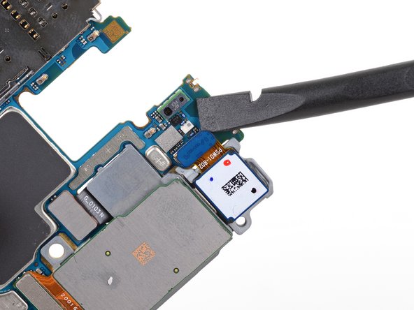
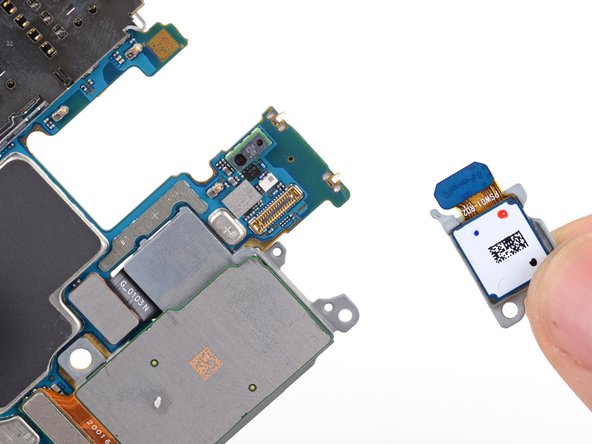

– Hey there! Time to show that ultrawide camera who’s boss! Grab your spudger’s flat end and gently pry up the ultrawide camera connector from the motherboard.
– Give a farewell wave to the ultrawide camera module as you remove it. Off to camera heaven it goes!
Tools Used
Step 40
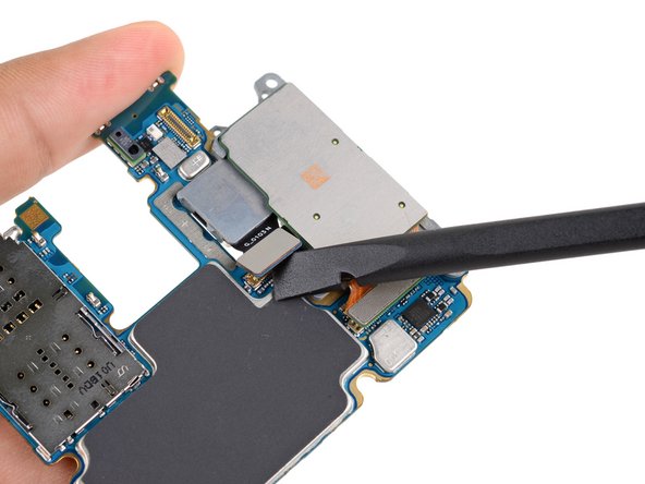
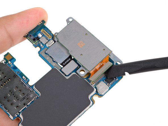

– Grab that spudger and gently lift up to disconnect the telephoto and wide-angle camera connector from the motherboard.
– Now, it’s time to pry up and disconnect the depth sensor. You’ve got this!
Tools Used
Step 41

– Say goodbye to that pesky rear-facing camera module and gently remove it from its cozy home.


