How to Replace Samsung Galaxy S20 Ultra Motherboard – Step-by-Step Tutorial
Duration: 45 minutes
Steps: 44 Steps
Hey there! 👋 If you’re encountering an issue while following our repair guide, don’t sweat it! 🙌 We’re here to help. If you need a hand, just give our friendly repair team a shout by scheduling a repair and they’ll guide you through it!
Get hip and groove through these steps to remove and replace the motherboard in the Galaxy S20 Ultra. Need replacement adhesive? We’ve got you covered so you can complete this repair with style. If you need help, you can always schedule a repair.
Step 1


– Grab a SIM card eject tool, a bit, or even a straightened paperclip and gently insert it into the tiny hole on the SIM tray, which you’ll find at the top edge of your phone, right next to the sleek plastic antenna band.
– Give it a firm press to pop that tray out. You’ve got this!
Tools Used

Step 2


– First things first, let’s pop that SIM card tray out! It’s like giving your phone a little breath of fresh air.
– When you’re ready to slide the SIM card back in, make sure it’s sitting just right in the tray. It’s all about that perfect fit!
– Oh, and don’t forget about the thin rubber gasket around the SIM tray – it’s your phone’s little superhero against water and dust. If it’s looking a bit worse for wear or has gone MIA, it’s a good idea to swap it out or get a new SIM tray altogether to keep your device safe and sound inside.
Step 3

First things first, give your phone a little break—unplug it and power it down before diving in.
– Warm up an iOpener and place it on the bottom edge of the back cover for a cozy two minutes.
Tools Used

Step 4


– Grab a suction cup and stick it on the back of your phone, aiming for the center of the bottom edge.
– Give that suction cup a good, steady pull to open up a little gap between the back cover and the frame.
– Now, slide the tip of an opening pick into that gap you’ve created.
Step 5


– Gently glide the pick back and forth along the bottom edge to cut through that stubborn adhesive like a pro.
– Keep your opening pick snugly in the seam to stop that pesky adhesive from sealing back up.
Step 6

– Warm up your iOpener and let it dance on the left edge of the back cover for about two minutes.
Tools Used
Step 7


Alright, folks, let’s get cracking! This might need a few tries due to the snug fit. Don’t worry, you’ll nail it in no time!
– Grab a suction cup and stick it to the back of your phone, aiming for the center of the left edge like a pro.
– Give that suction cup a good, steady pull to open up a little gap between the back cover and the frame. You’ve got this!
– Slide the tip of an opening pick into that gap and let the magic happen.
Step 8


– Gently slide the pick under the edge of the glass, giving it a little tilt and sliding it further to smoothly detach the adhesive holding the back cover in place.
Step 9


– Gently slide the pick down towards the bottom edge of your phone to break free the back cover’s sticky grip.
– Keep your pick tucked under the left edge of the glass near the bottom of the device to stop that adhesive from making a comeback.
Step 10


– Slide another pick right under the center of the left edge of the back cover.
– Gently glide the pick up towards the top of the device to break free the back cover’s adhesive.
– Keep your pick tucked under the left edge of the glass near the top to stop that adhesive from sticking back down.
Step 11

– Warm up a heated iOpener and place it on the right edge of the back cover for a cozy two minutes.
Tools Used
Step 12


– First things first, grab a suction cup and stick it onto the back of your phone, aiming for the center of the right edge. You’ve got this!
– Now, give that suction cup a good, firm pull. You’re creating a tiny gap between the back cover and the frame. Keep it steady!
– With that gap in place, take the point of your opening pick and slide it in there. You’re doing great!
Step 13


– Gently slide the pick down towards the bottom edge of the phone to release the back cover’s adhesive.
– Keep your pick snug under the right edge of the glass near the bottom of the device to prevent the adhesive from sealing back up.
Step 14


– Slip another pick under the middle of the right edge of the back cover.
– Gently move the pick upwards to detach the adhesive on the back cover.
Step 15

– Warm up the top edge of the back cover with a cozy iOpener for two minutes. It’s like giving your device a little spa treatment!
Tools Used
Step 16


The glass around the corners of the back cover has a bit of a curve and is quite prone to cracking. So, take it easy during this step to keep your back cover safe and sound!
– Gently work that pick from the right edge of your device around the top right corner like you’re giving it a little massage.
– Keep gliding along the top edge to totally free the back cover from its adhesive buddy.
Step 17


– Gently raise the back cover while humming your favorite tune. Use opening picks to gracefully glide through any lingering adhesive.
– Bid farewell to the back cover as you lift it away.
– Remember for the rebuild:
Step 18


– Grab a spudger and gently lift up to disconnect the wireless charging coil connector.
Tools Used

Step 19


– Grab a trusty pair of tweezers and gently coax that wireless charging coil away from your device. Take it slow and steady!
– Bid farewell to the wireless charging coil as you remove it from the device.
– When it’s time to put everything back together, make sure to reconnect the wireless charging coil connector first. This will help it sit right where it needs to be. After that, give the rest of the coil a firm press to secure it in place.
Tools Used

Step 20

– Grab your trusty Phillips #00 screwdriver and take out those five 3.9 mm-long screws holding the motherboard bracket in place. You’ve got this!
Tools Used

Step 21

– Easily detach the motherboard bracket using tweezers. Time to show that motherboard who’s boss!
Tools Used


Step 23

– Grab your trusty Phillips #00 screwdriver and get ready to remove those five 3.9 mm-long screws holding the loudspeaker and lower midframe in place. Let’s show those screws who’s boss!
Tools Used
Step 24


– Get the point of a spudger or a pair of tweezers and slide it into the cozy notch located in the top left corner of the midframe. Gently lift it up to set free the clips that are holding everything together.
– Bid farewell to the loudspeaker and lower midframe as you lovingly detach them from their place.
Step 25

– When it’s time to show those flex cables who’s boss, grab a spudger and gently pry them up and disconnect them from the daughterboard at the bottom of your device.
– To bring those connectors back together in perfect harmony, line them up like a pro and press down on one side until you hear that satisfying click. Then do the same on the other side. Remember, no middle pressing allowed! If things look a bit wonky, those pins might get bent out of shape, and we don’t want any permanent damage, do we?
Tools Used
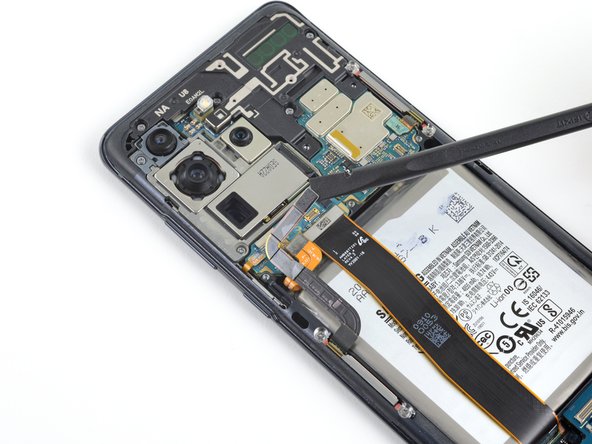
Step 26


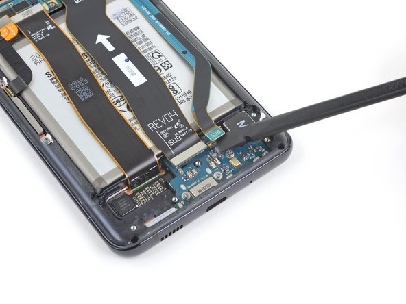
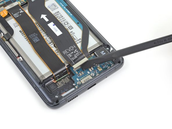
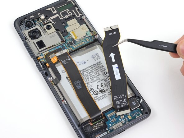
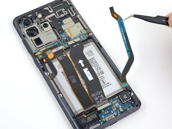
– Time to work your magic with a spudger! Gently pry up and disconnect those main and auxiliary flex cables from the motherboard.
Tools Used

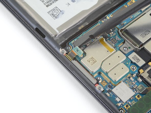
Step 28

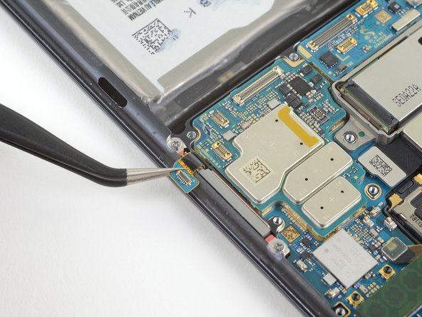
– Gently lift and unplug the left 5G antenna cable from the motherboard. Remember, a little finesse goes a long way!
Step 29


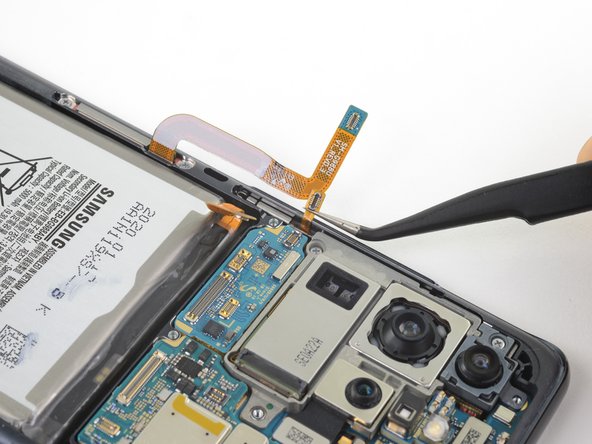
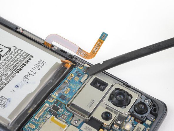
– Gently lift and unplug the main display flex cable from the motherboard. Remember, a little finesse goes a long way!
Step 30


– Carefully lift and bend the display along with the left 5G antenna flex cables to clear the path for the motherboard and battery.
Step 31

– Alrighty, buddies! Time to get your fixin’ on with a trusty #00 Philips screwdriver. Un-screw those four 3.9 mm-long midframe protectors and let’s start the recovery process. Need a hand? We’ve got your back; just schedule a repair and we’ll be there in a jiffy!
Tools Used

Step 33

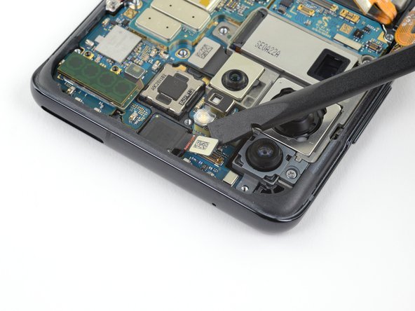
– Gently lift and detach the right 5G antenna flex cable from its cozy spot on the motherboard.
– Grab a trusty pair of tweezers to elegantly guide the cable away from the motherboard.
Tools Used
Step 34

– Gently pry up and disconnect the side button flex cable from its motherboard home.
– Bend the cable aside with care, away from the motherboard.
Step 35

– Gently lift and say goodbye to the front facing camera flex cable as it detaches from the motherboard.
– Guide the cable away from the motherboard like a smooth operator.

Step 37

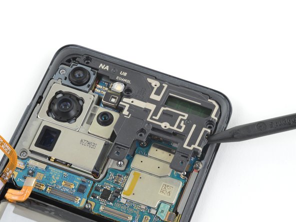
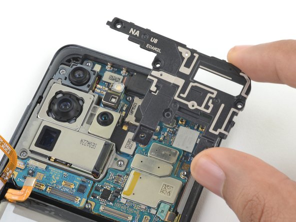
– Alright, techies! Lets rock n’ roll! Firstly, use the flat end of a spudger to pry up the corner of that 5G antenna module, it’s like transforming a robot! Next, yank out that pesky 5G antenna module. Now, during reassembly, be strategic and reconnect that 5G antenna connector first, so it lines up nicely, and bam! Press down the rest of the antenna firmly, and voila, it sticks! If you need help, you can always schedule a repair with the coolest crew in town!
Tools Used
Step 38

– Grab your trusty Phillips #00 screwdriver and let’s get those two 3.9 mm-long screws out that are holding the motherboard and camera assembly in place. You’ve got this!
Tools Used
Step 39


– Alrighty, let’s pop open this gadget and see what’s goin’ on! First, slide that little tool in and give it a friendly nudge under there to help separate the motherboard from the phone body without breaking a sweat. Once that’s done, gently remove the motherboard assembly, and you’re practically there! 🚀 If anything seems a bit much, or you’re thinkin’, ‘Hmm, this might be safer with a pro,’ you can always schedule a repair!👍
Tools Used
Step 40

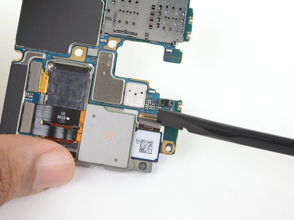
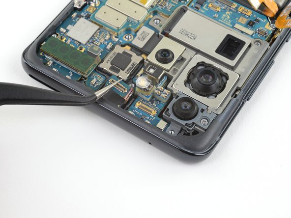
– Gently lift and unplug the ultrawide camera connector from the motherboard. You’ve got this!
Step 41
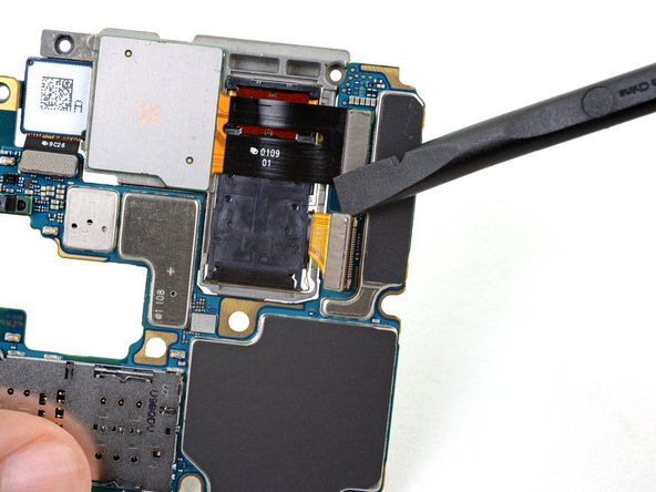

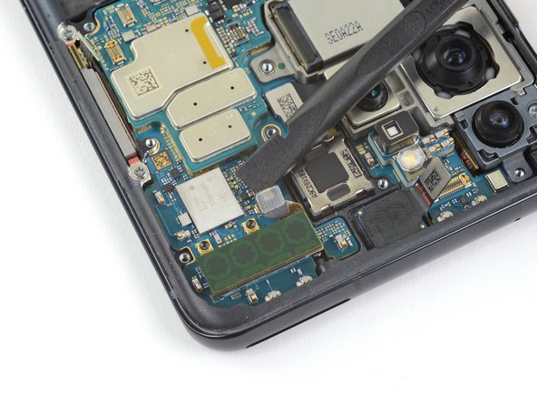
– Gently lift and unplug the telephoto and wide-angle camera connectors from the motherboard. You’ve got this!
Step 42

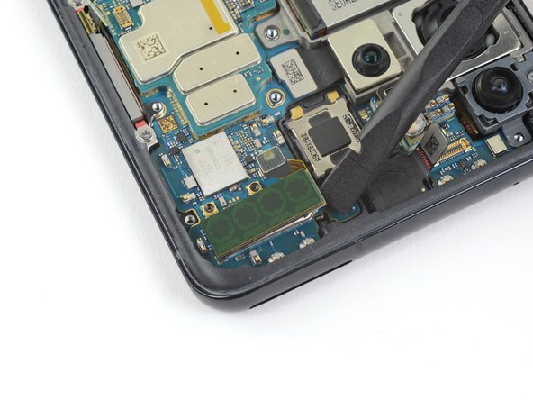
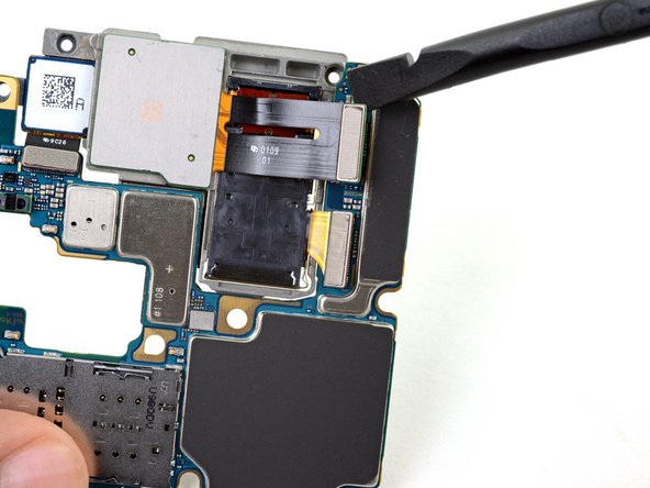
– Turn the motherboard assembly upside down like flipping a pancake! Next, gently lift up and disconnect the depth sensor connector from the motherboard. You’re doing great!
Step 43

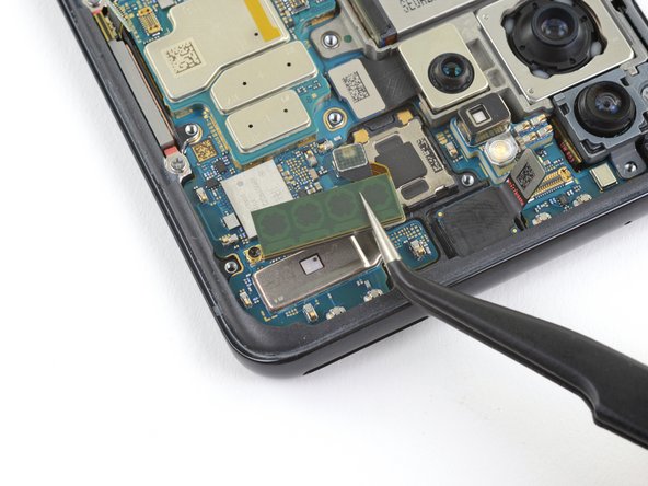
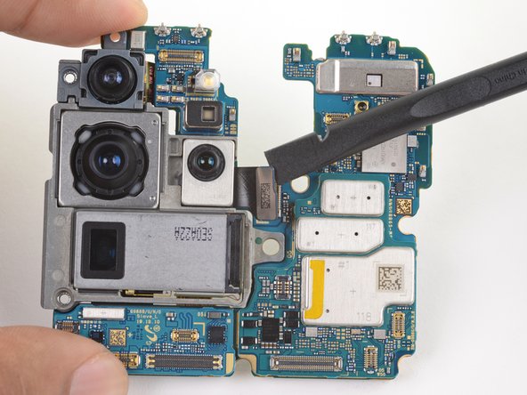
When swapping out individual cameras, you might need to carefully detach and move some of the existing cameras over to your shiny new module. You’ve got this!
– Gently detach the rear-facing camera module and set it aside with care.
Step 44

– Ubuntu se! The motherboard is now all that’s left. If you need any assistance, you can always schedule a repair.


