How to Replace Samsung Galaxy S7 Edge Audio Jack – DIY Guide
Duration: 45 min.
Steps: 23 Steps
In this guide, we’re here to help you tackle the task of swapping out that pesky, faulty headphone jack on your Galaxy S7 Edge all by yourself! If your headphones have gone silent and you’re missing your tunes, it’s time to roll up your sleeves and get to work. And remember, if you need assistance along the way, you can always schedule a repair.
Step 1
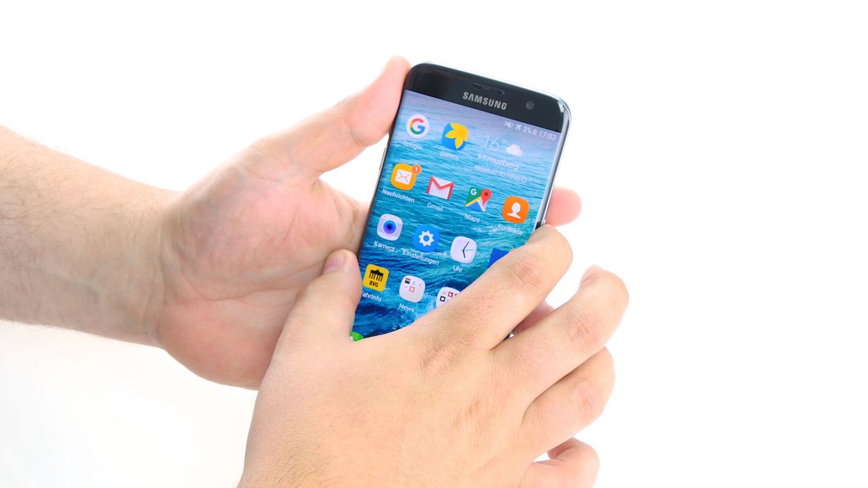
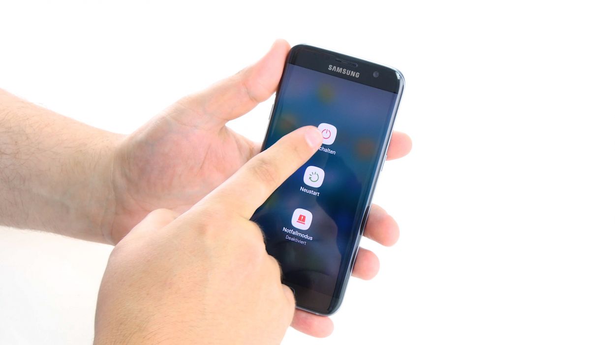
– First things first, let’s power down your device! Just press and hold that power button until you see the ‘Power off’ option pop up on your screen.
– Now, give it a little tap with your finger to confirm you want to shut down your Galaxy S7 Edge, and then sit back and relax while the screen goes blank. You’ve got this!
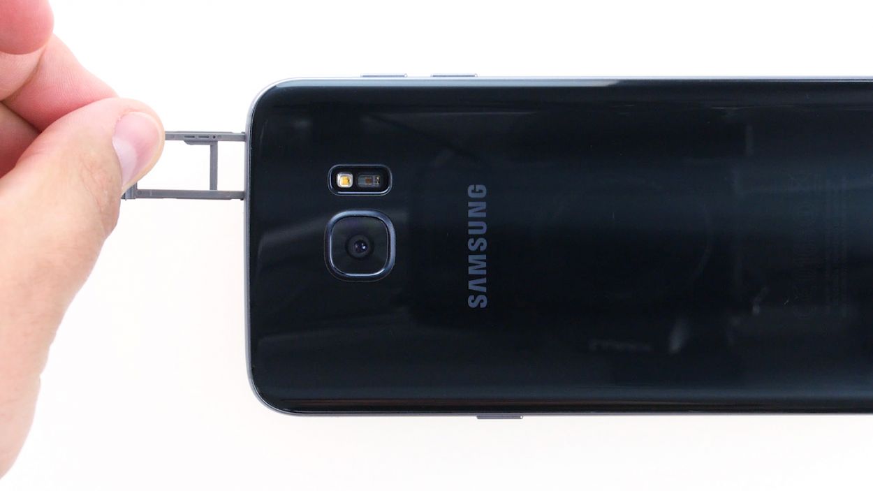
Step 2
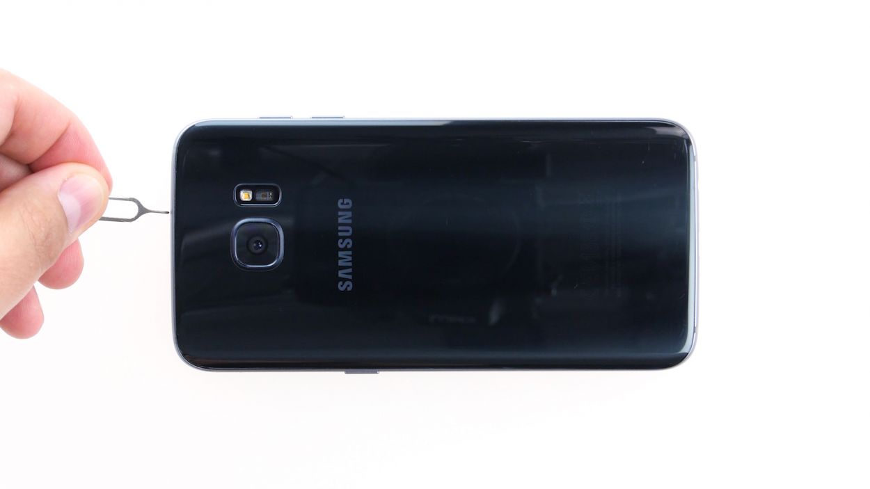

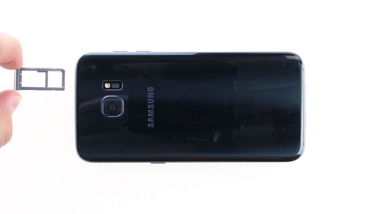
– Use the SIM tool to eject the SIM tray from your device and then remove the tray with your fingers.
Step 3

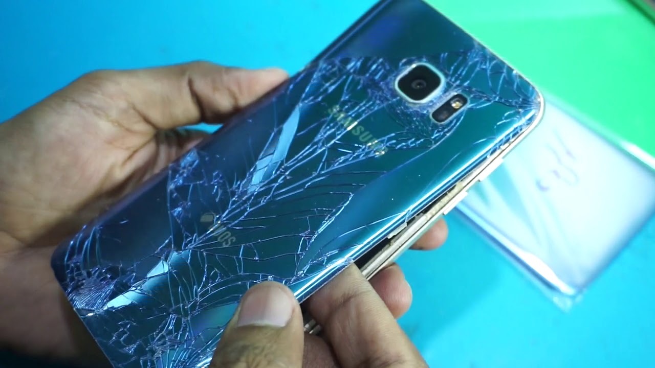
The inside of the back cover has a paint job. Gently remove any sticky leftovers to keep it looking sharp and avoid any scratches or cracks!
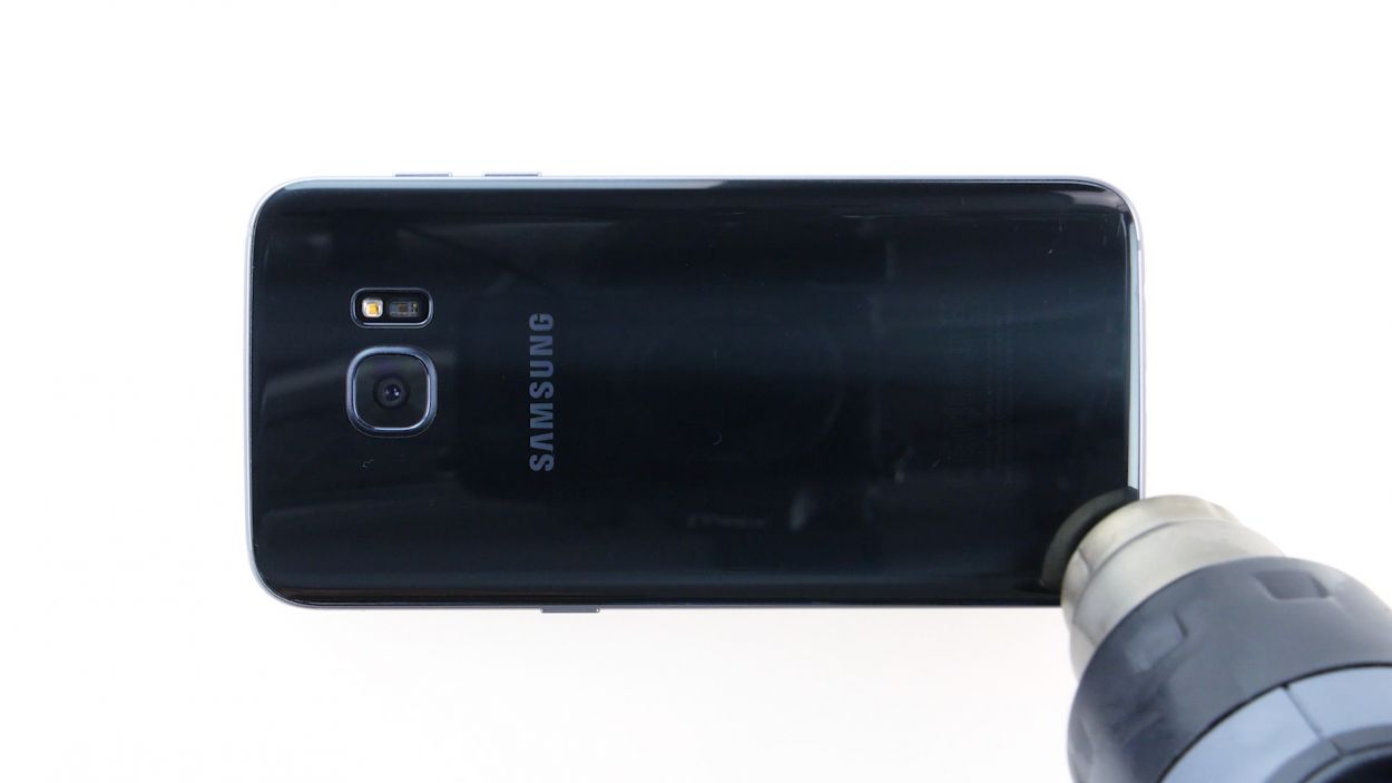
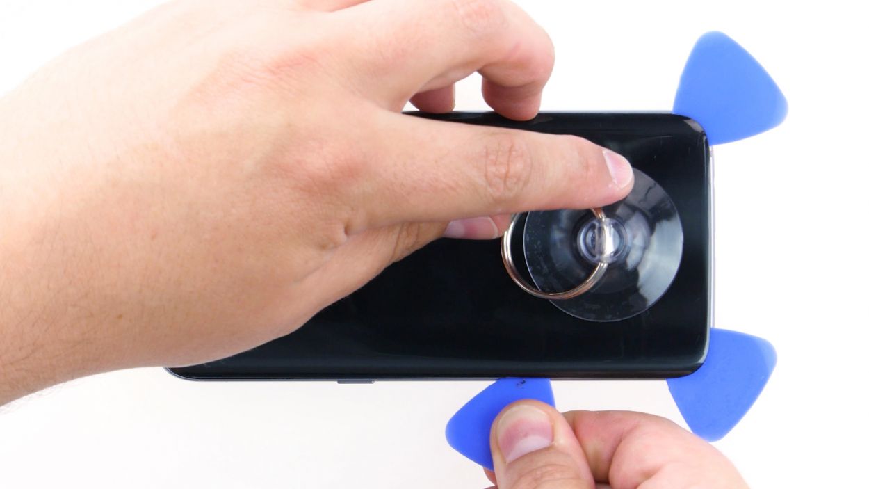
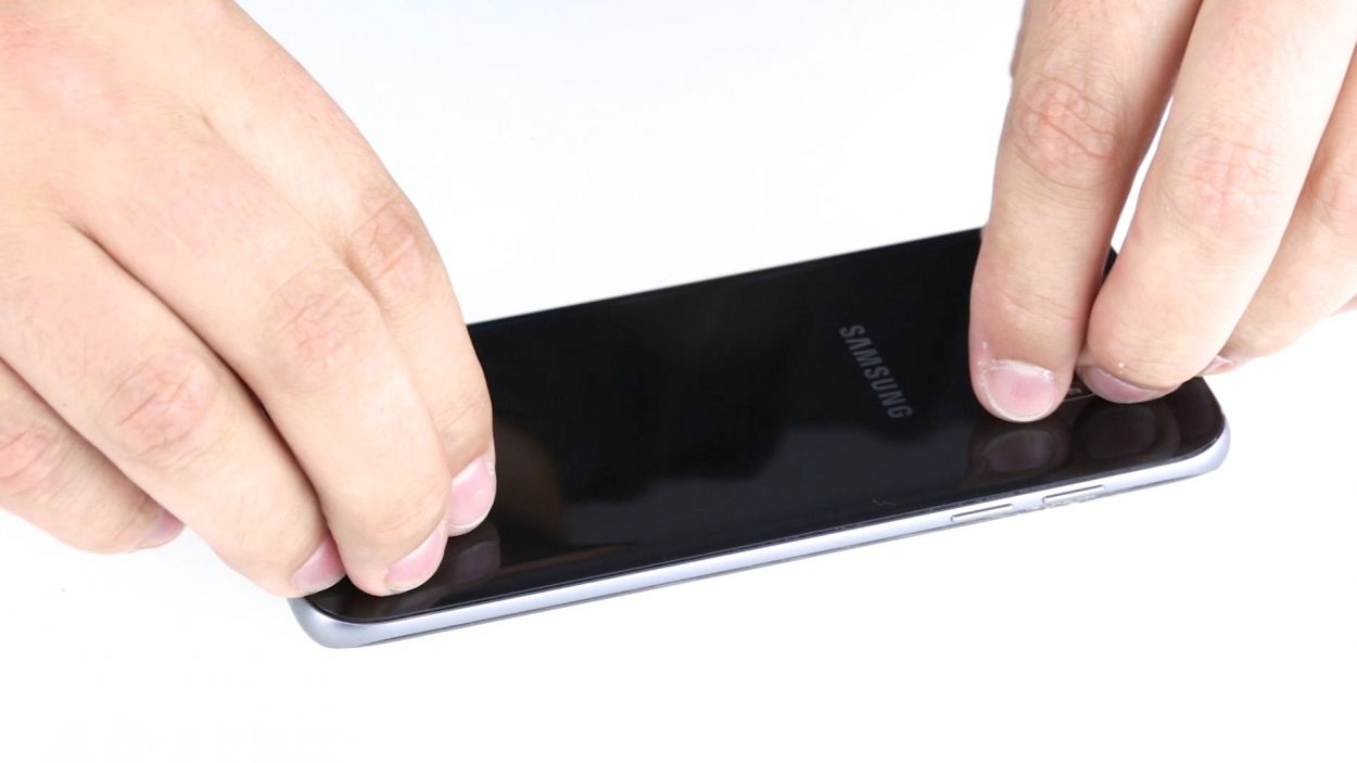
– The back cover is stuck on there pretty good! Grab a suction cup and gently pull it away. A pick can help you nudge it free from the frame. A little hot air can work wonders, so warm up your device first to loosen that pesky glue.
– Once you see a gap forming between the back cover and the chassis, slide that pick in there! Just a heads up, the inside of the back cover is painted, so be careful when removing any leftover adhesive to keep it looking sharp.
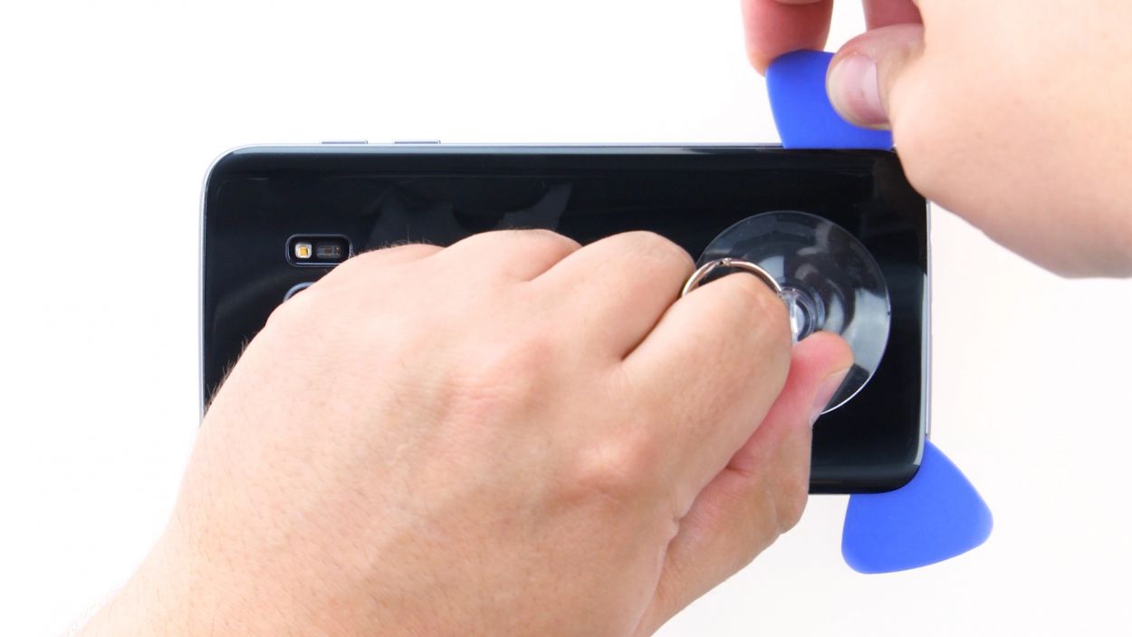
– Use a few more picks to work your way around the corners, gently prying them apart one by one.
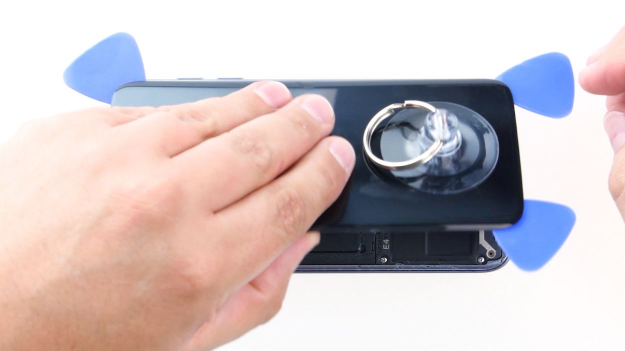
– Once all the glue is free, go ahead and lift off the back cover. You’re doing great!
Tools Used
- heat gun to heat parts that are glued on so they’re easier to remove.
In most cases, you can also use a hairdryer.” rel=”noopener”>Heat gun - Flat Picks
- VAKUPLASTIC Suction Cup
Step 4
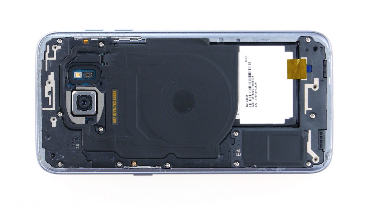
12 × 3.3 mm PH00 Phillips screws
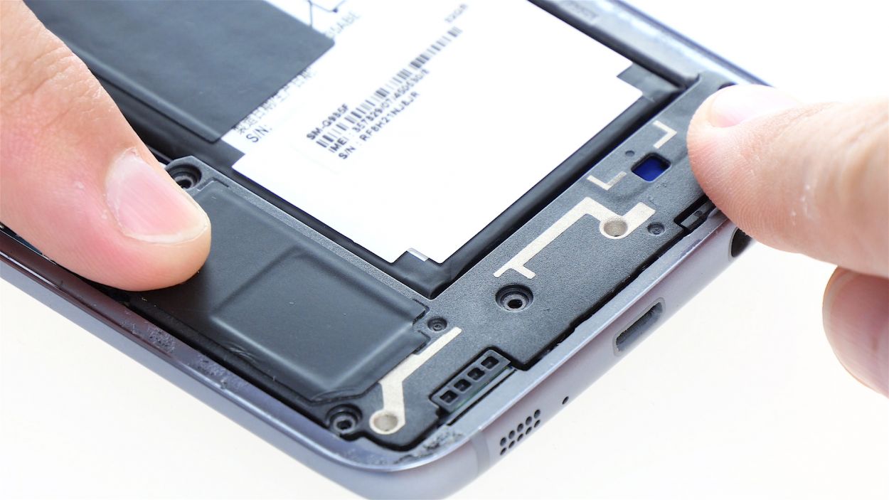
– Let’s tackle those twelve screws holding those antennas in place. Grab your trusty screwdriver and unscrew them with care!
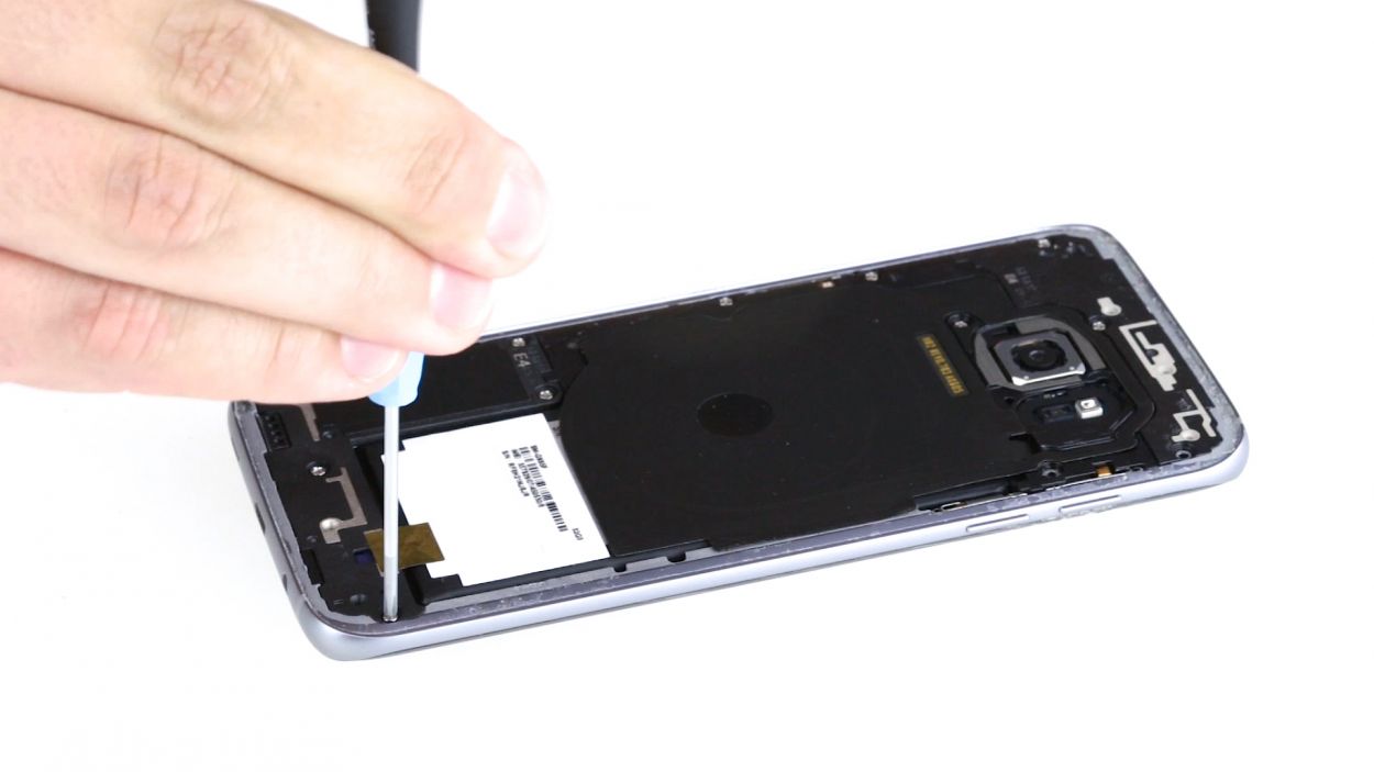
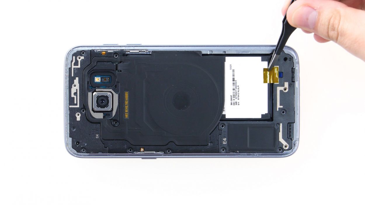
– Next up, say goodbye to that stubborn yellow adhesive strip. A little tug and it should come right off!
Tools Used
Step 5
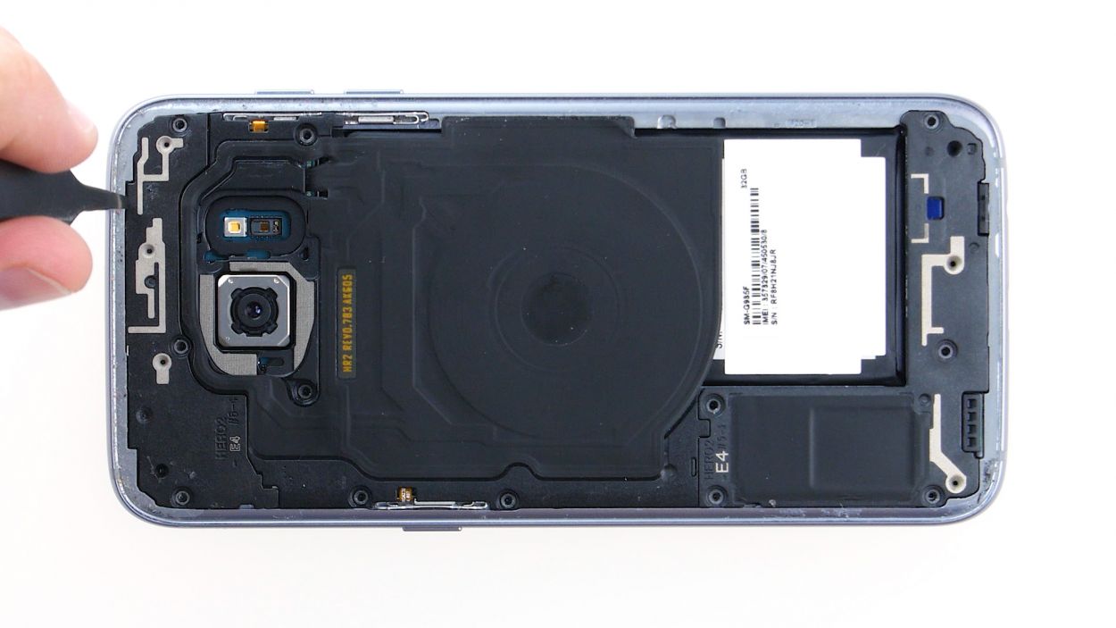
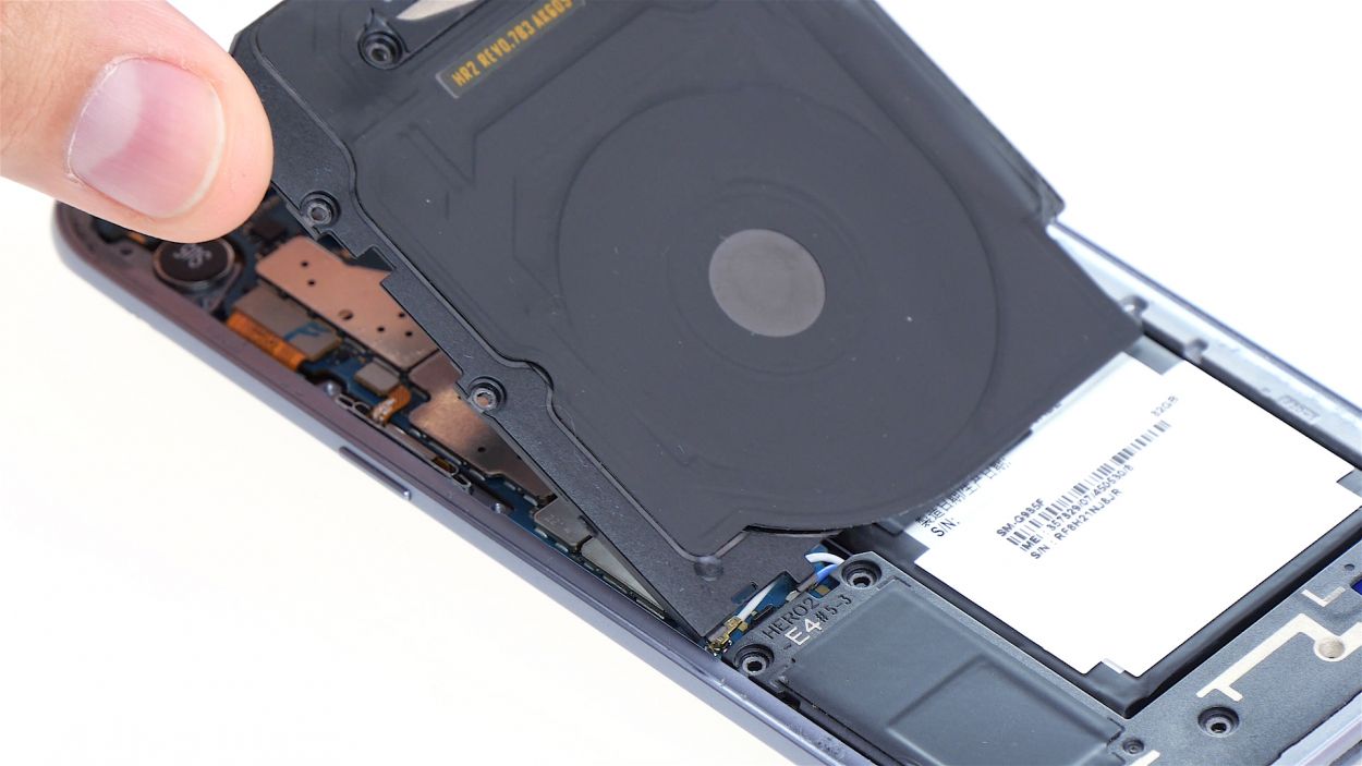
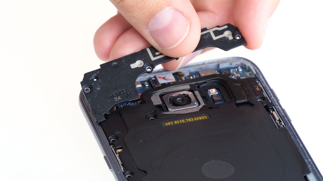
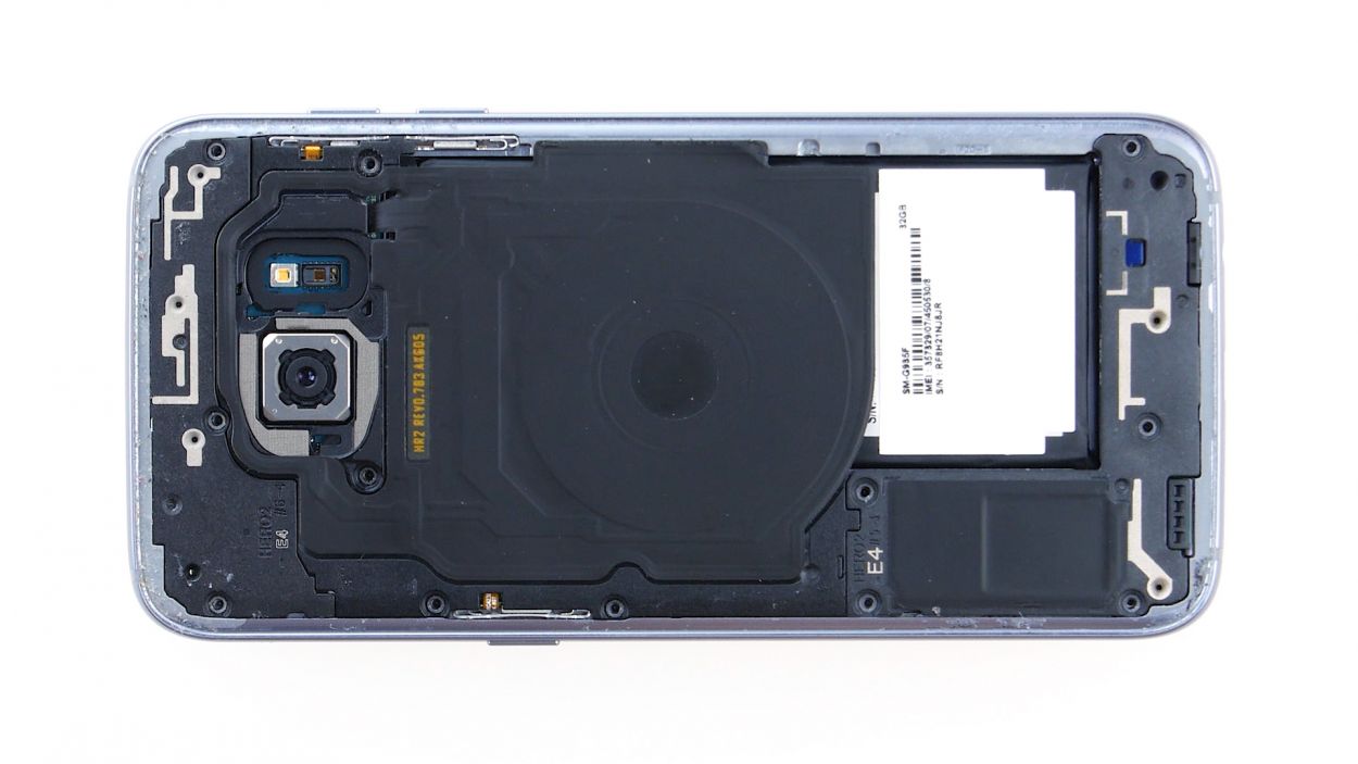
– Start by disconnecting the upper antenna from the enclosure. It’s just hanging out there, so begin at the upper right corner and gently unhook it.
– Once the right side is free, give a little tug in the middle to help the left side come loose too. It’s like a dance, just a little pull!
– Now, carefully remove the antenna from the enclosure. You’ve got this!
Step 6
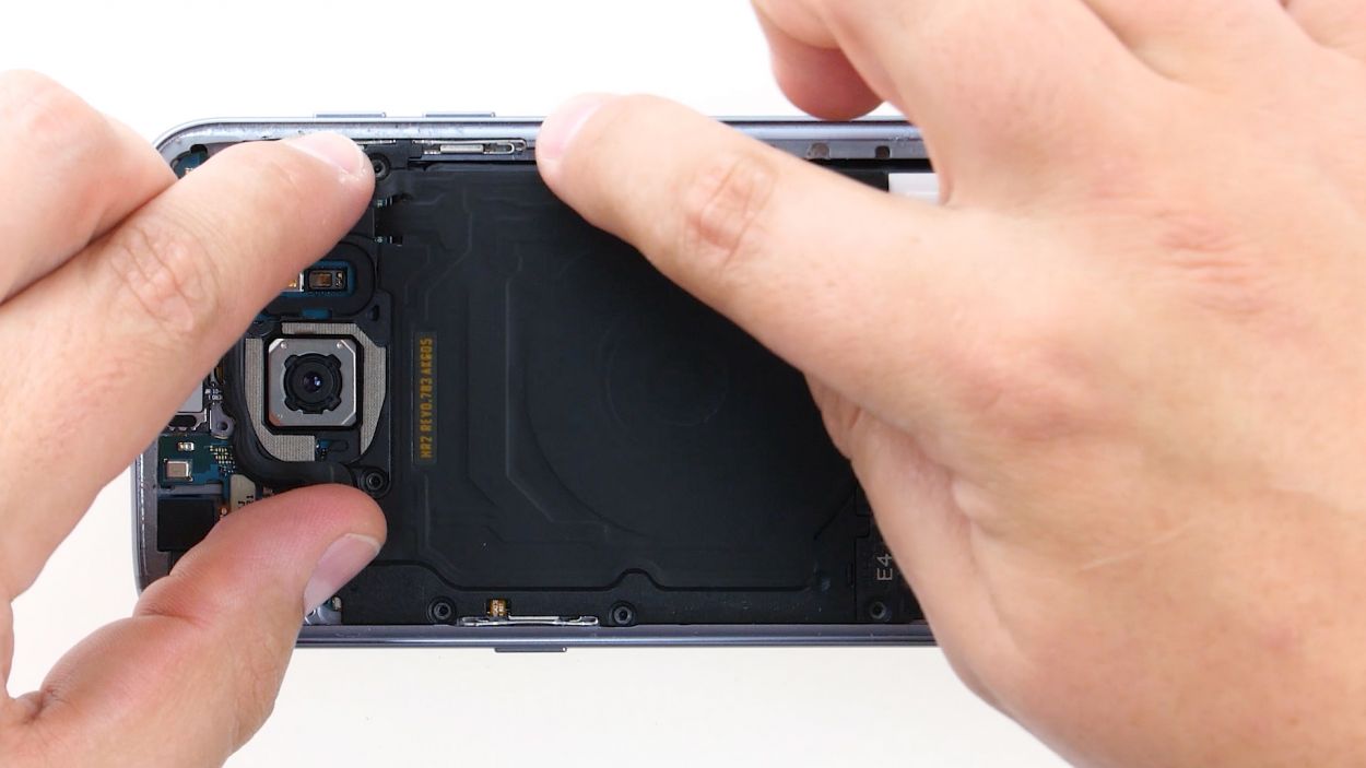
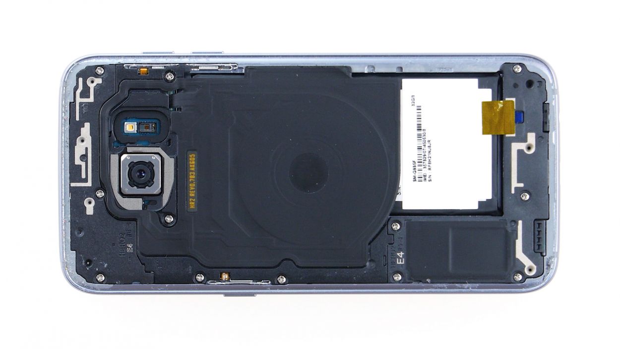
– Gently wiggle the middle antenna free from the enclosure, keeping in mind that it’s connected to the lower antenna. You’ve got this!
Step 7
– Using your trusty tweezers, gently unhook the lower antenna from the left side. It’s like giving it a little hug goodbye!
– Now, carefully lift the antenna out of the enclosure. You’ve got this!
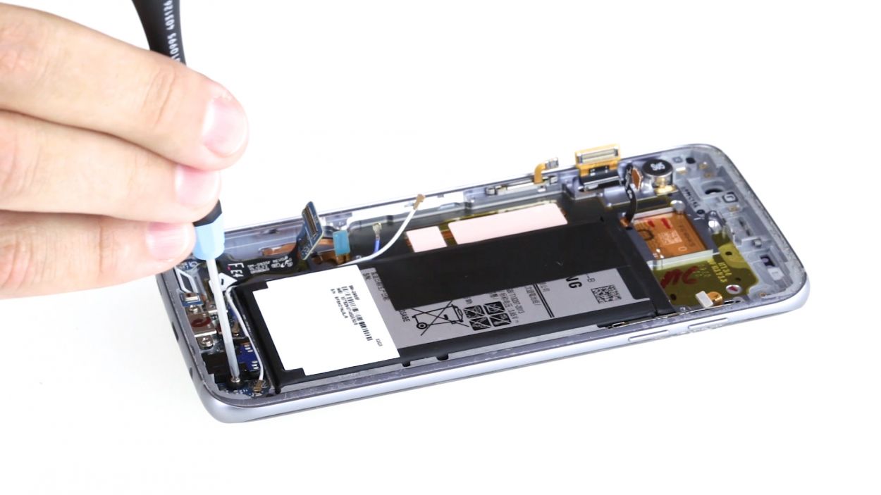
Step 8
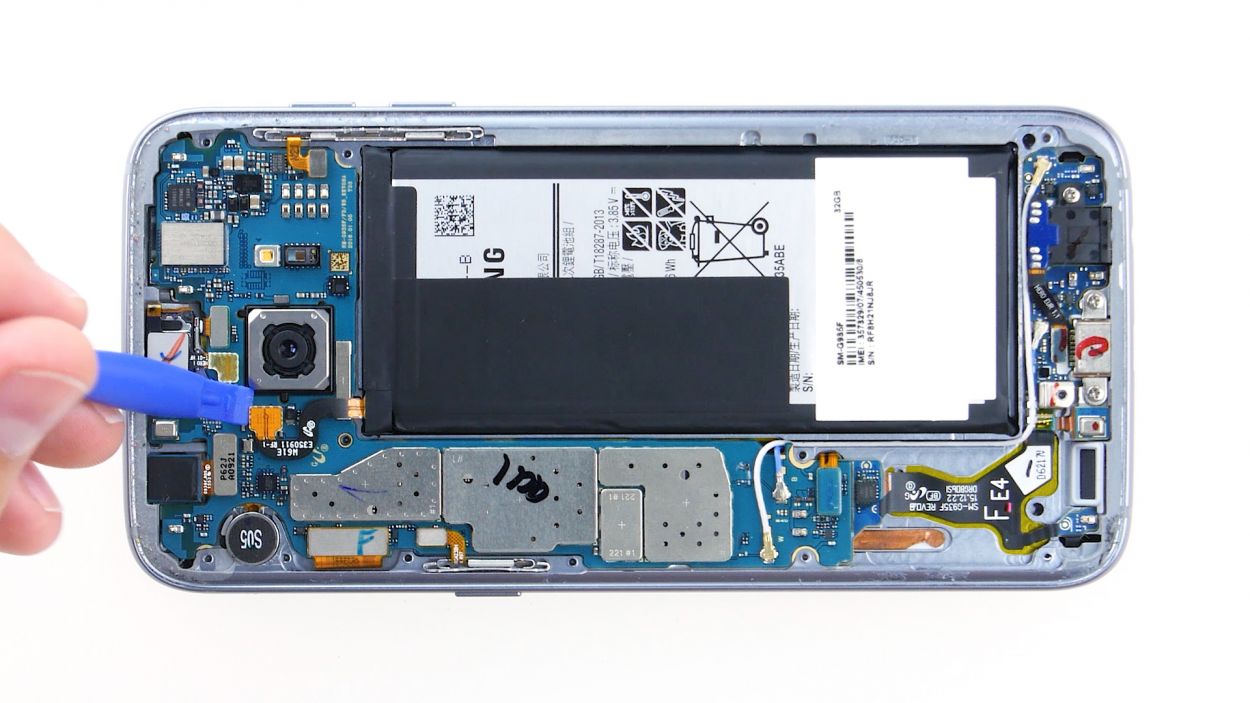
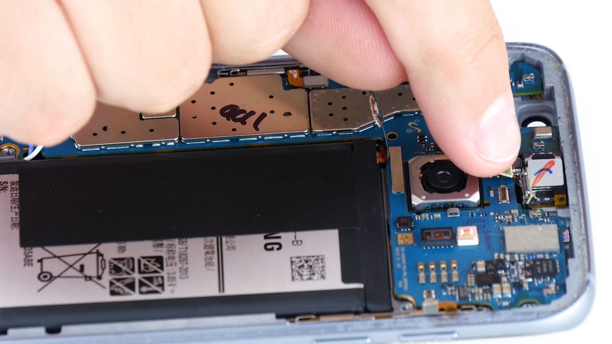
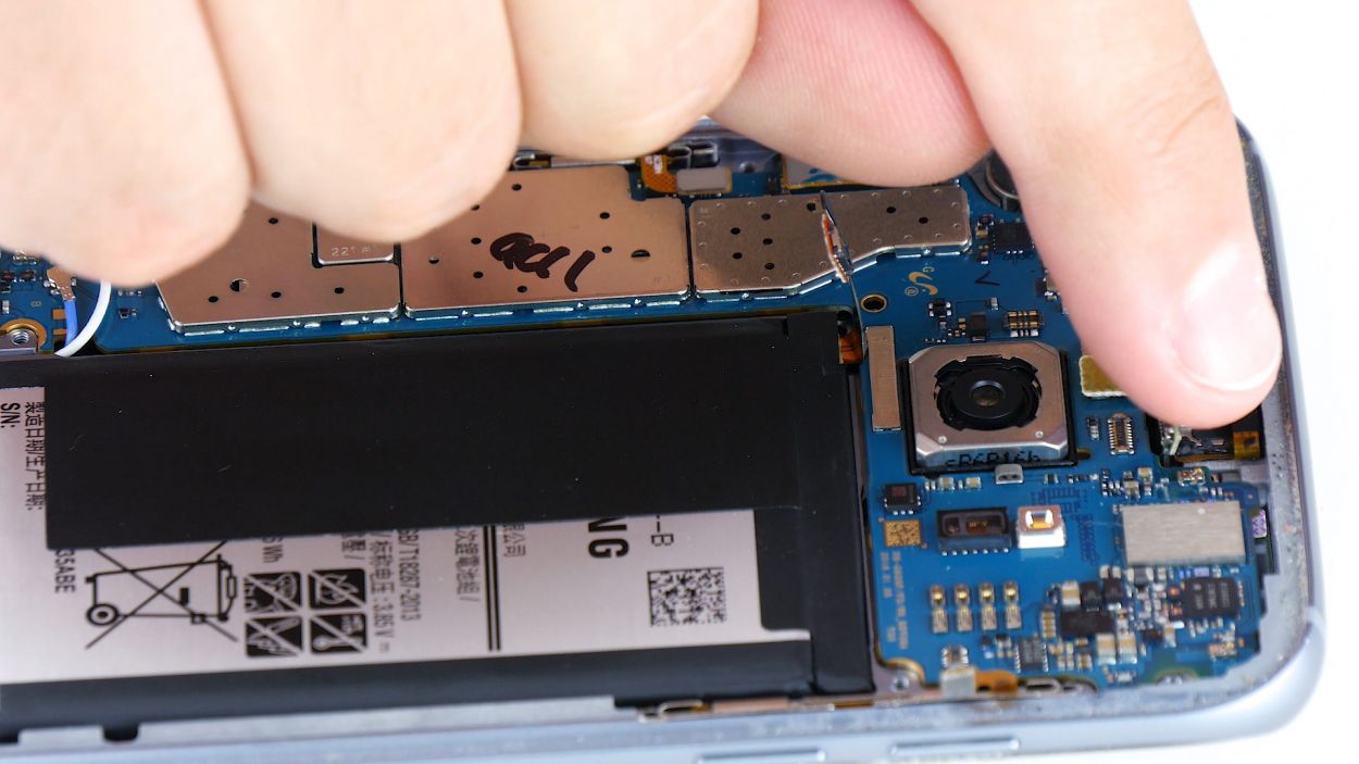
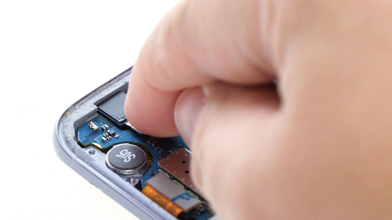
– Grab your trusty spudger and gently wiggle that battery contact free from the motherboard. Just a little nudge and it should pop right out of the socket!
Step 9
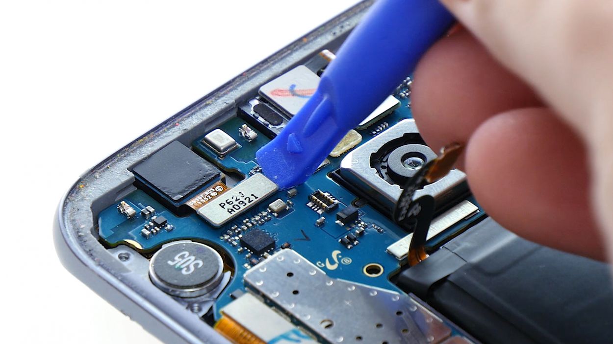
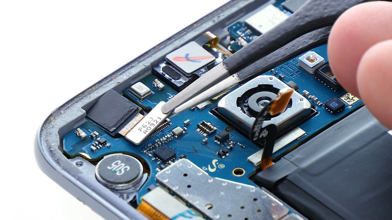
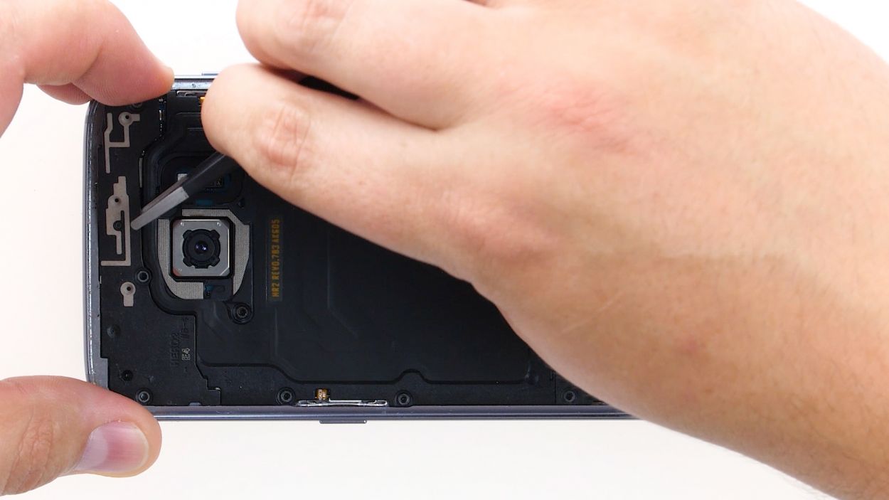
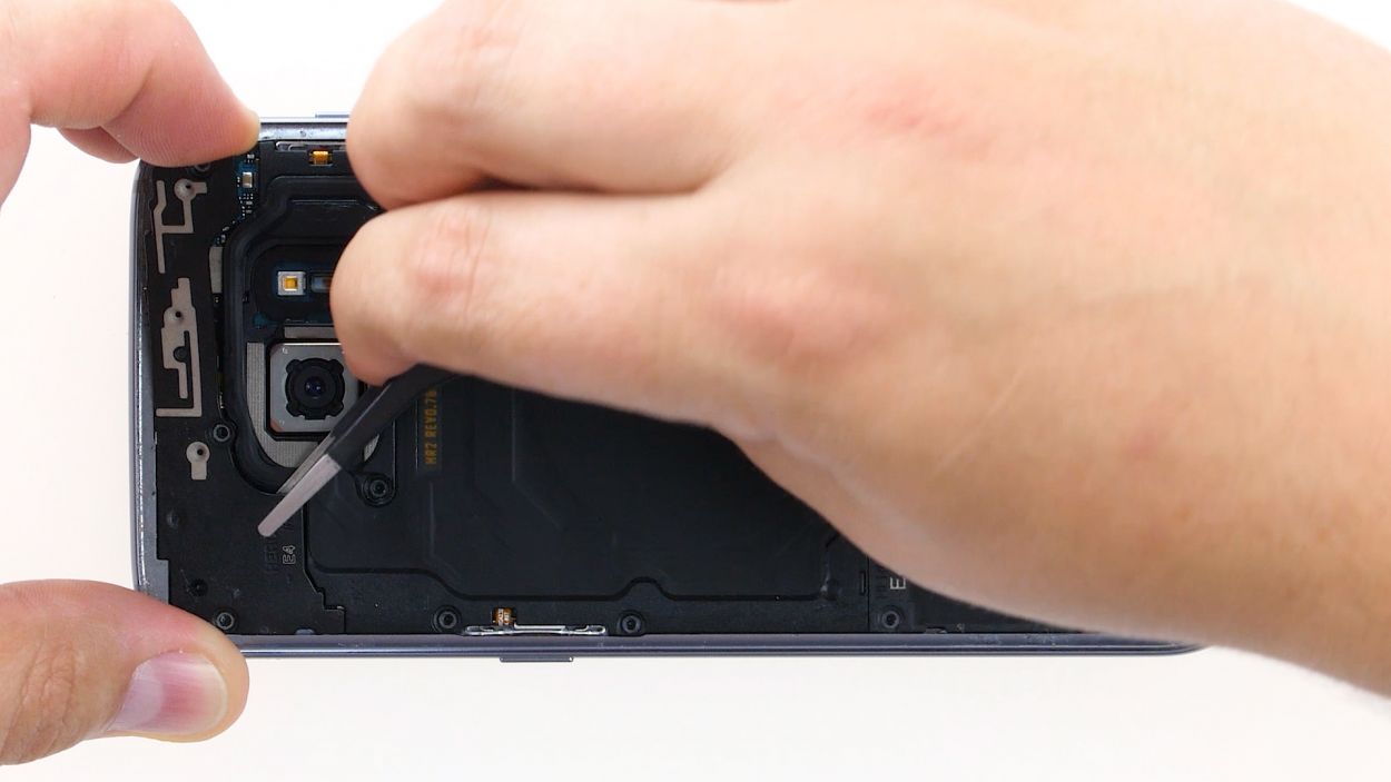
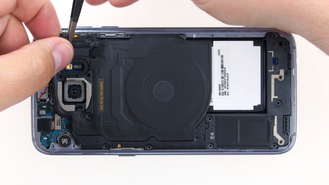
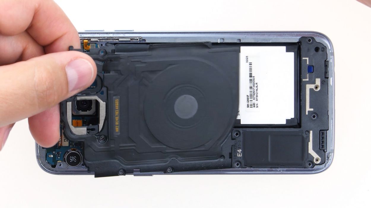
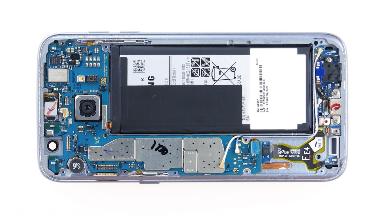
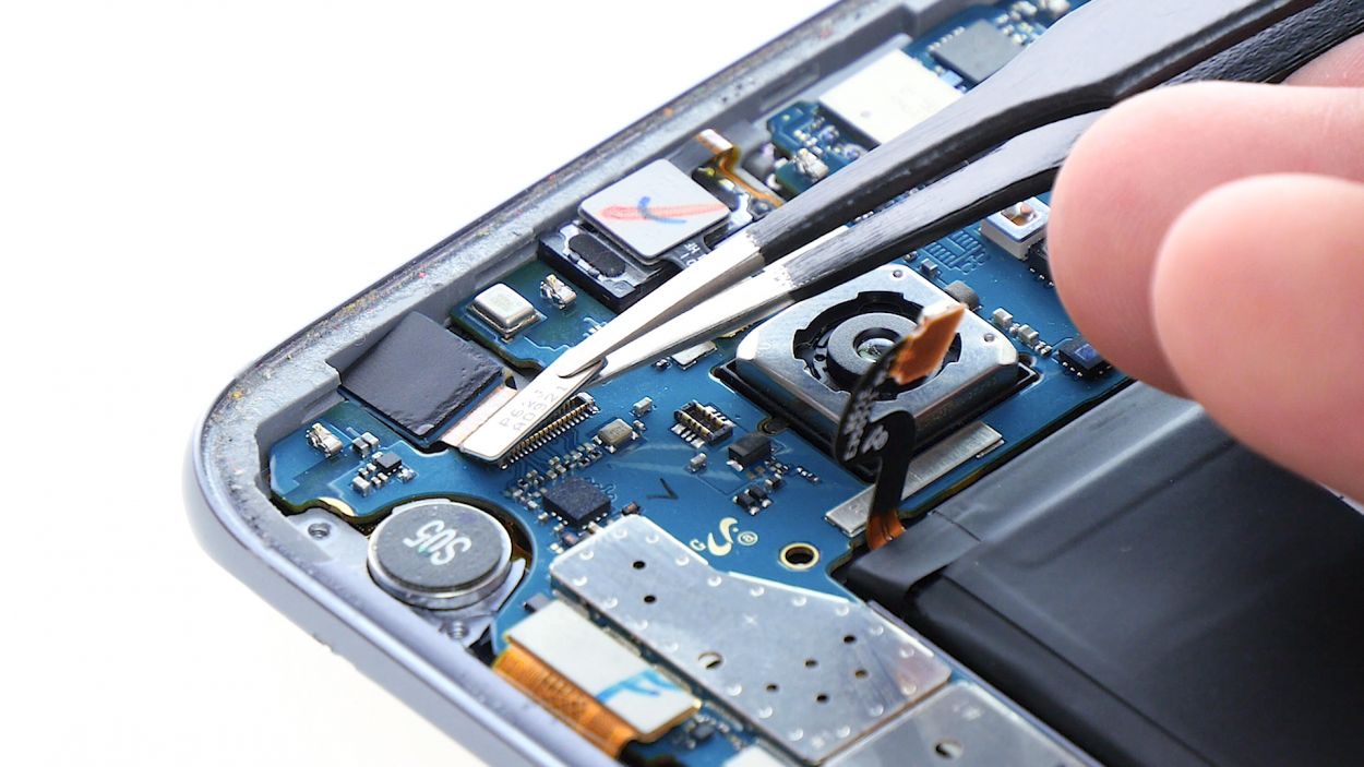
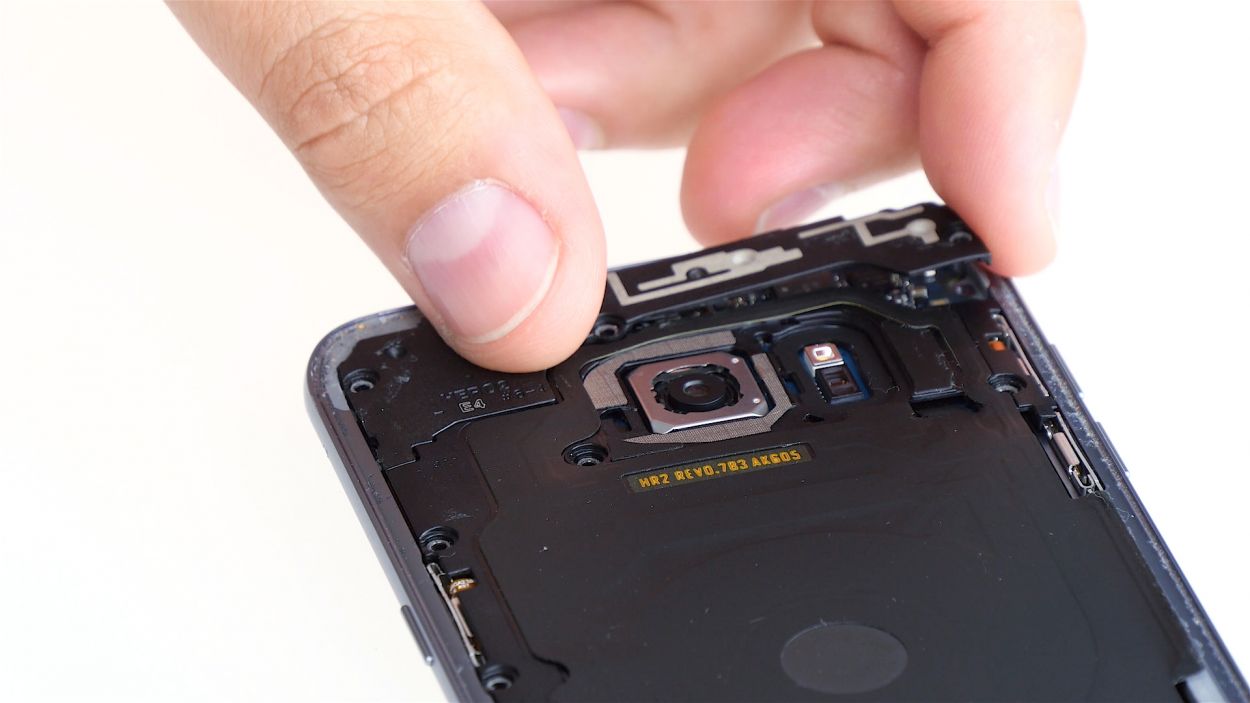
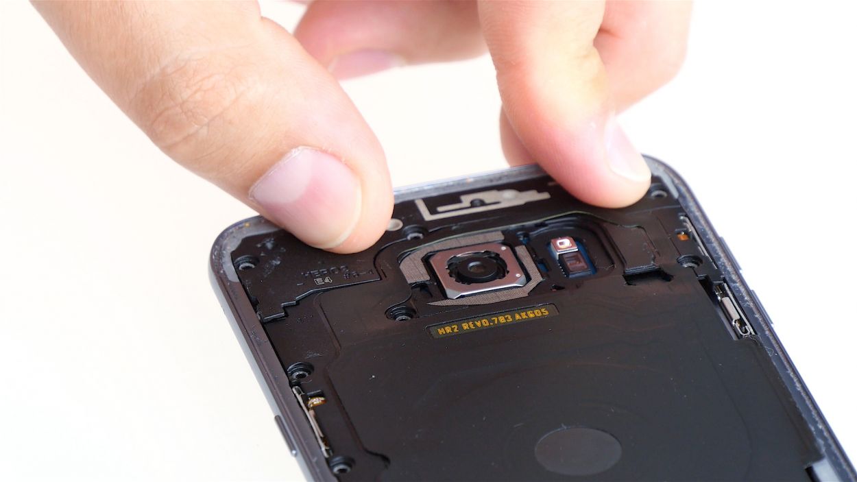
– Grab your trusty spudger and gently disconnect the front camera’s connector from the motherboard. Easy peasy!
– Now, go ahead and lift the front camera out of its cozy little home in the enclosure.
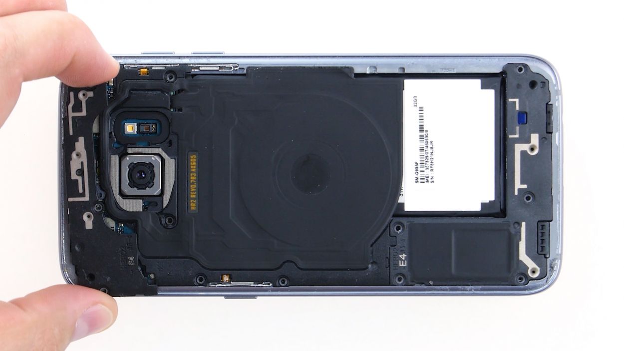
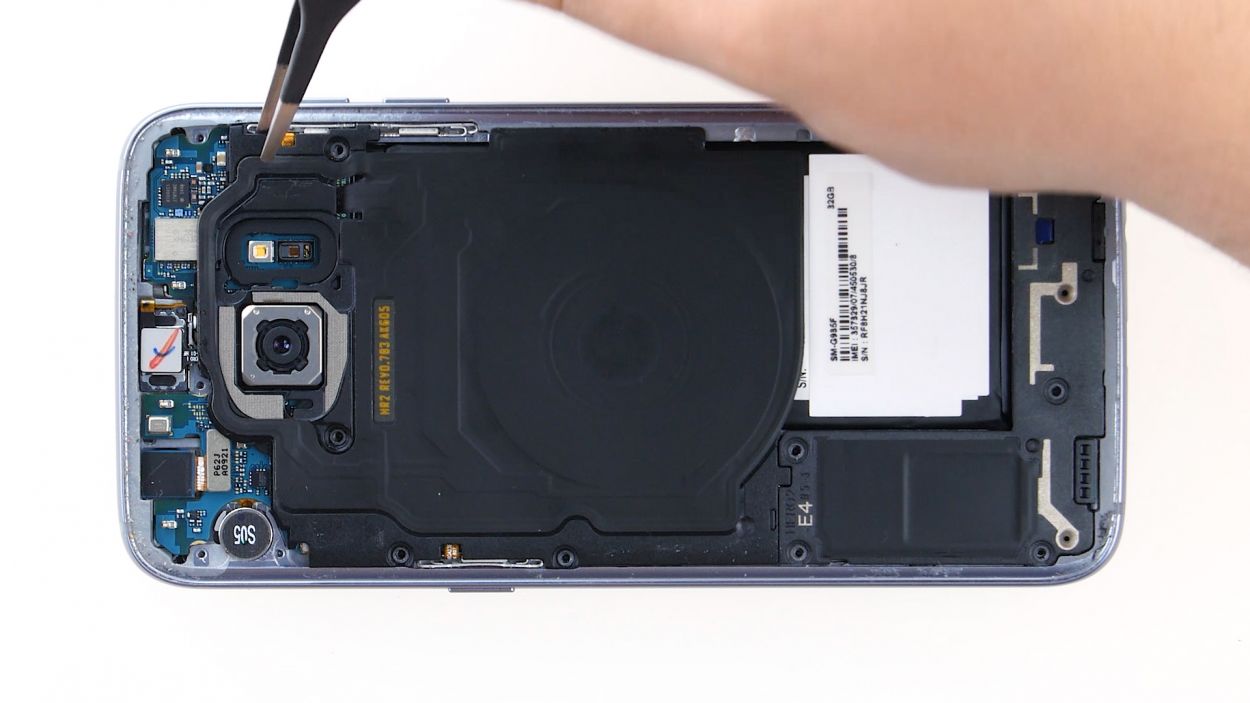
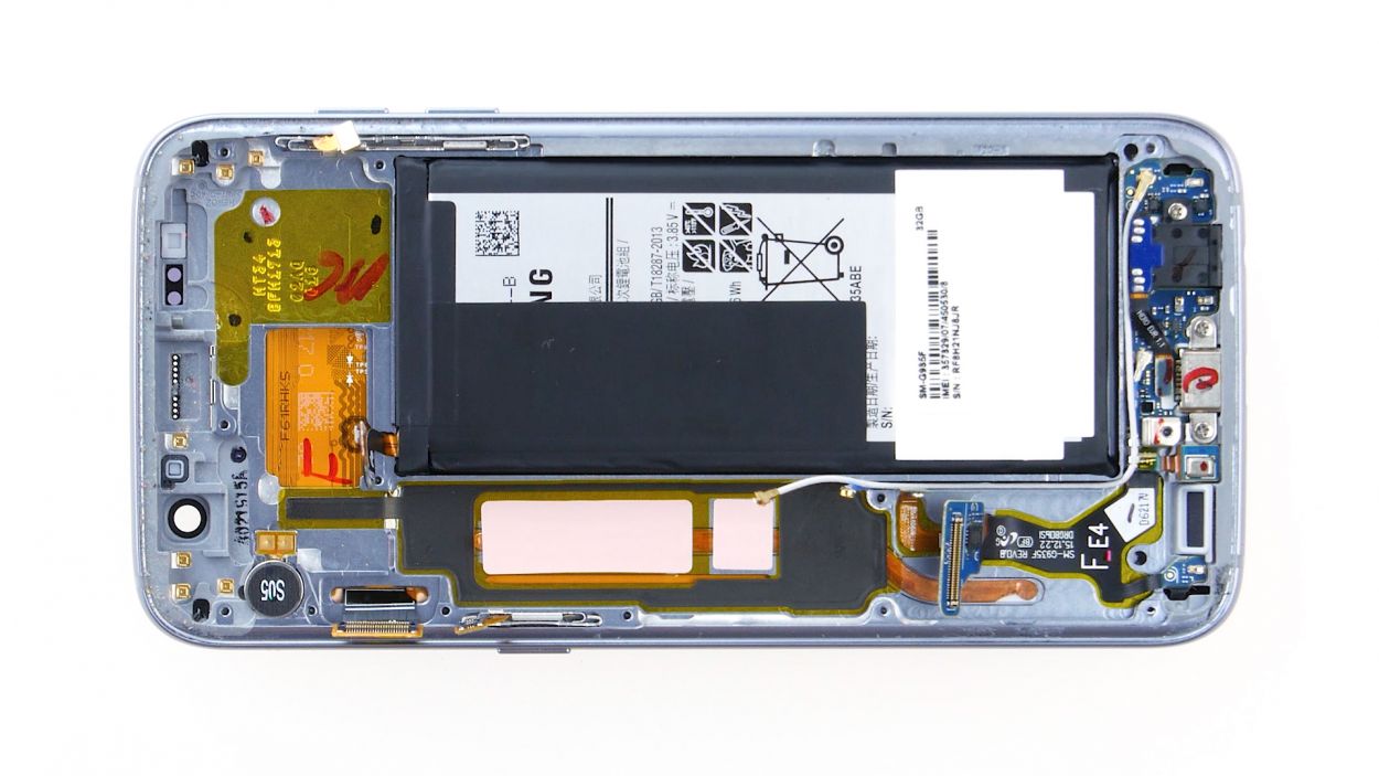
Step 10
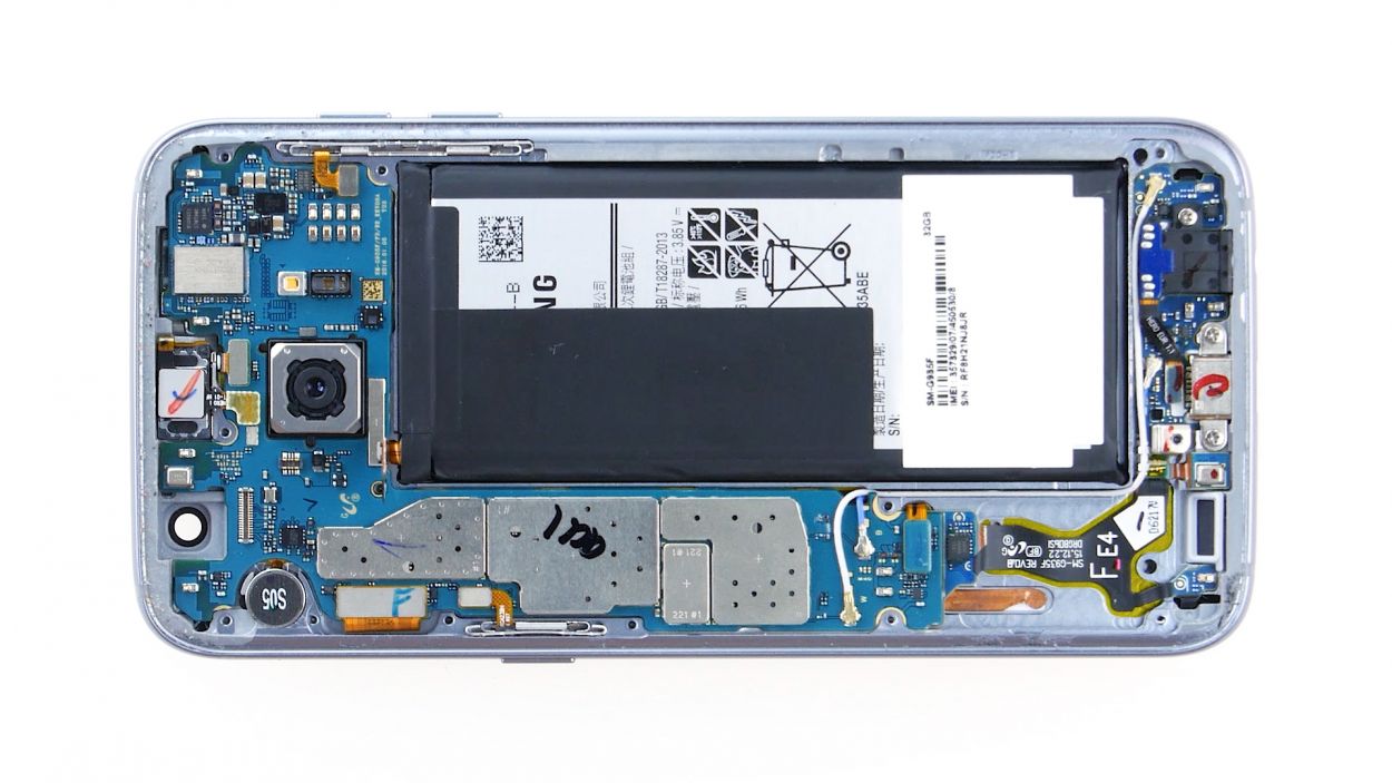
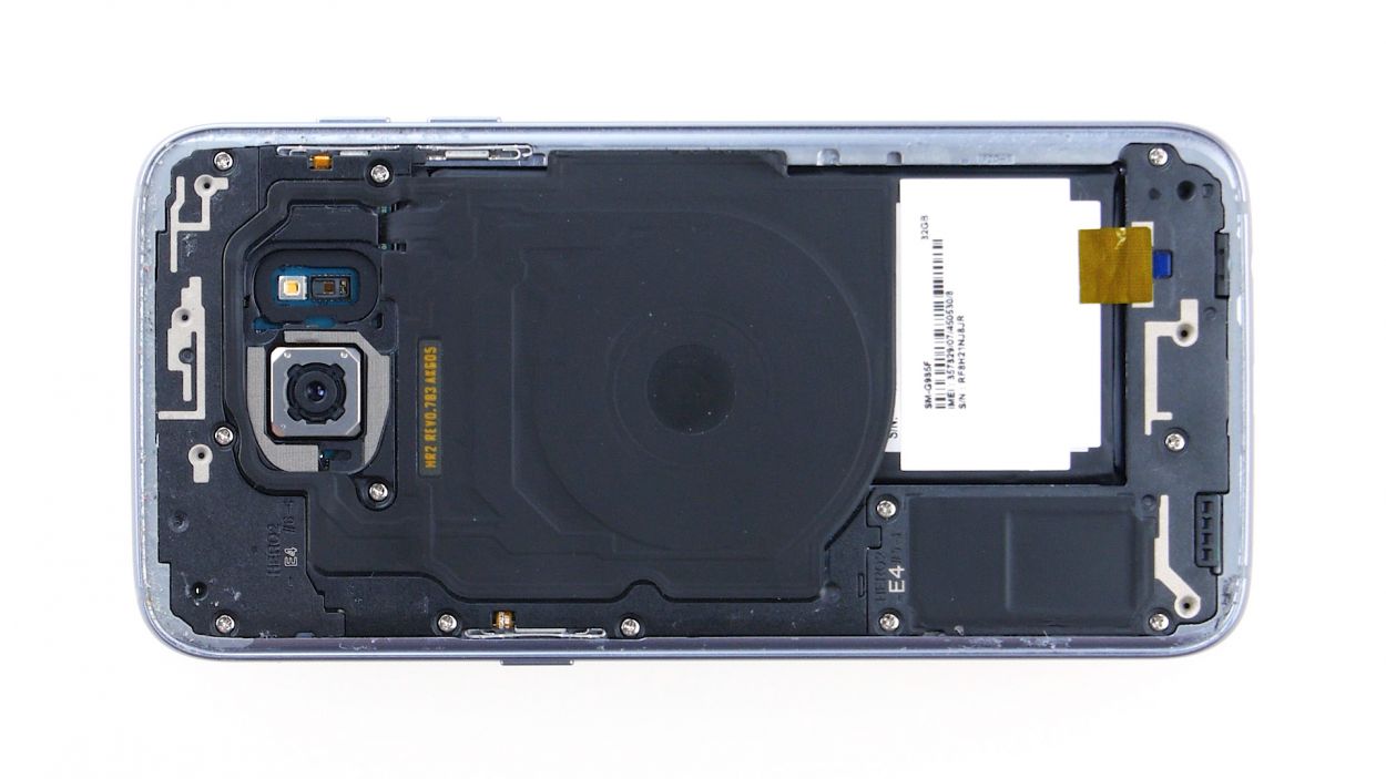
Volume Connector
Proximity Sensor
Earpiece Connector
Display
Power-Button
Antenna
Sensors
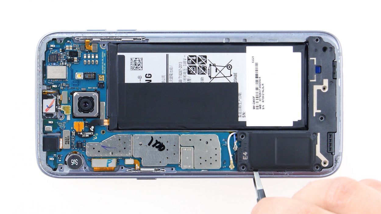
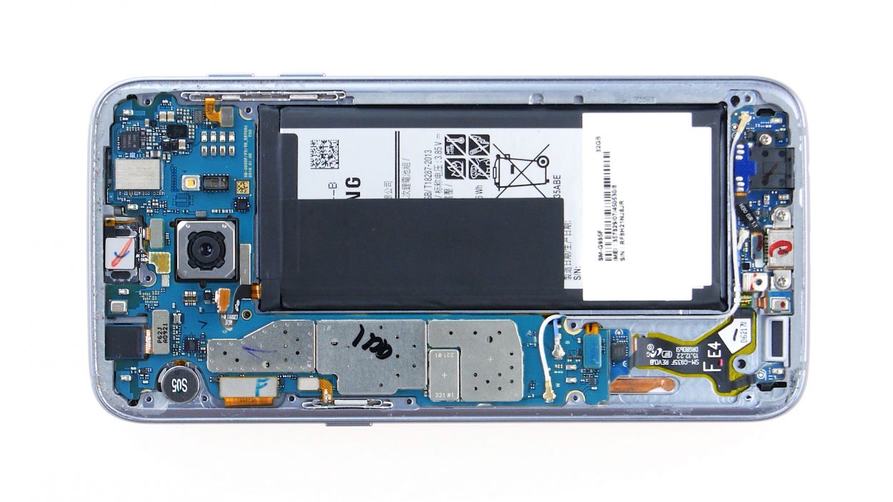
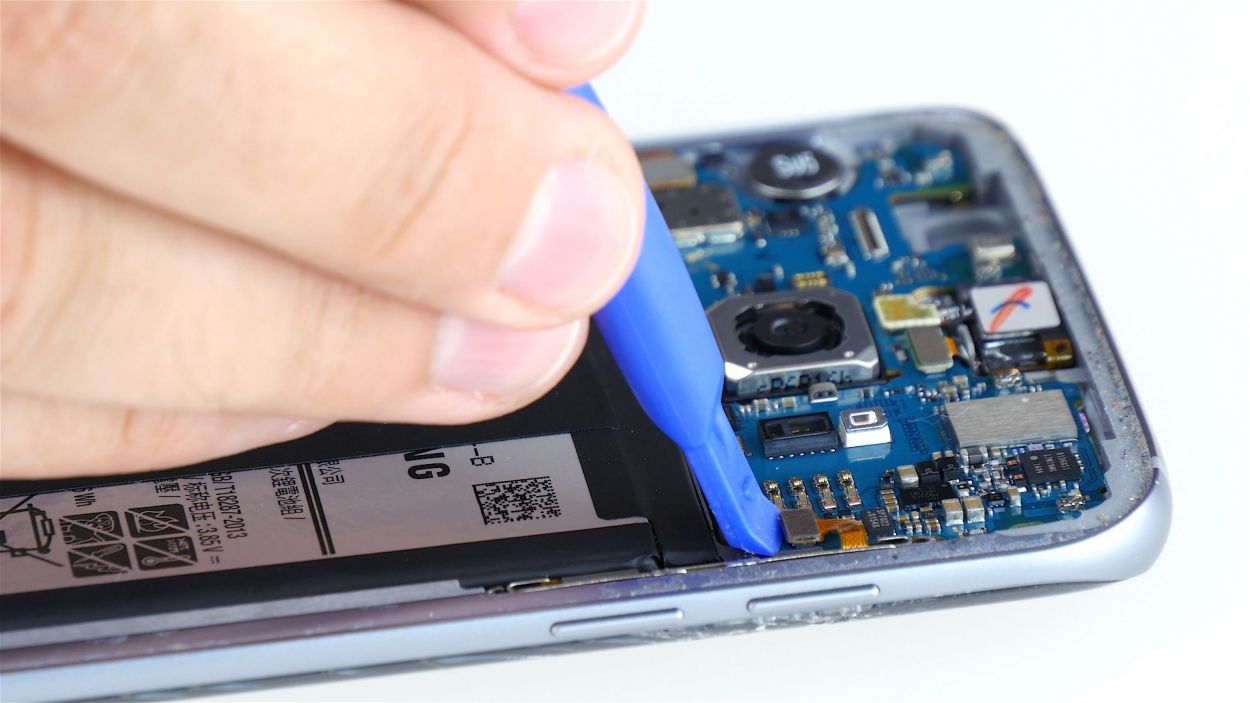
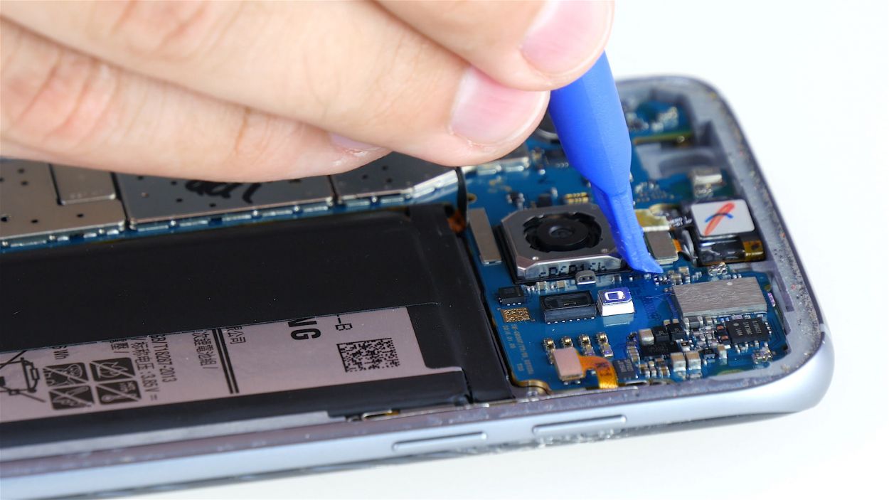
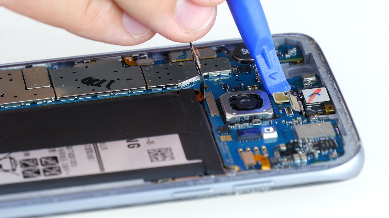
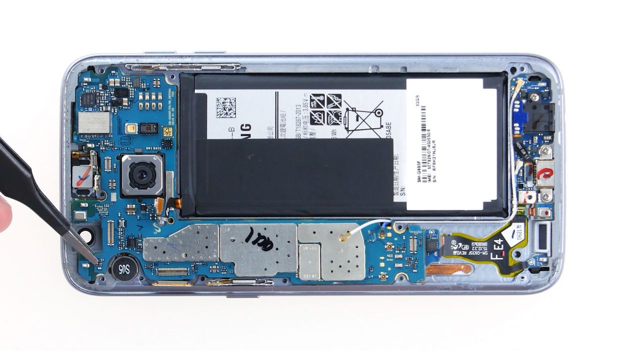
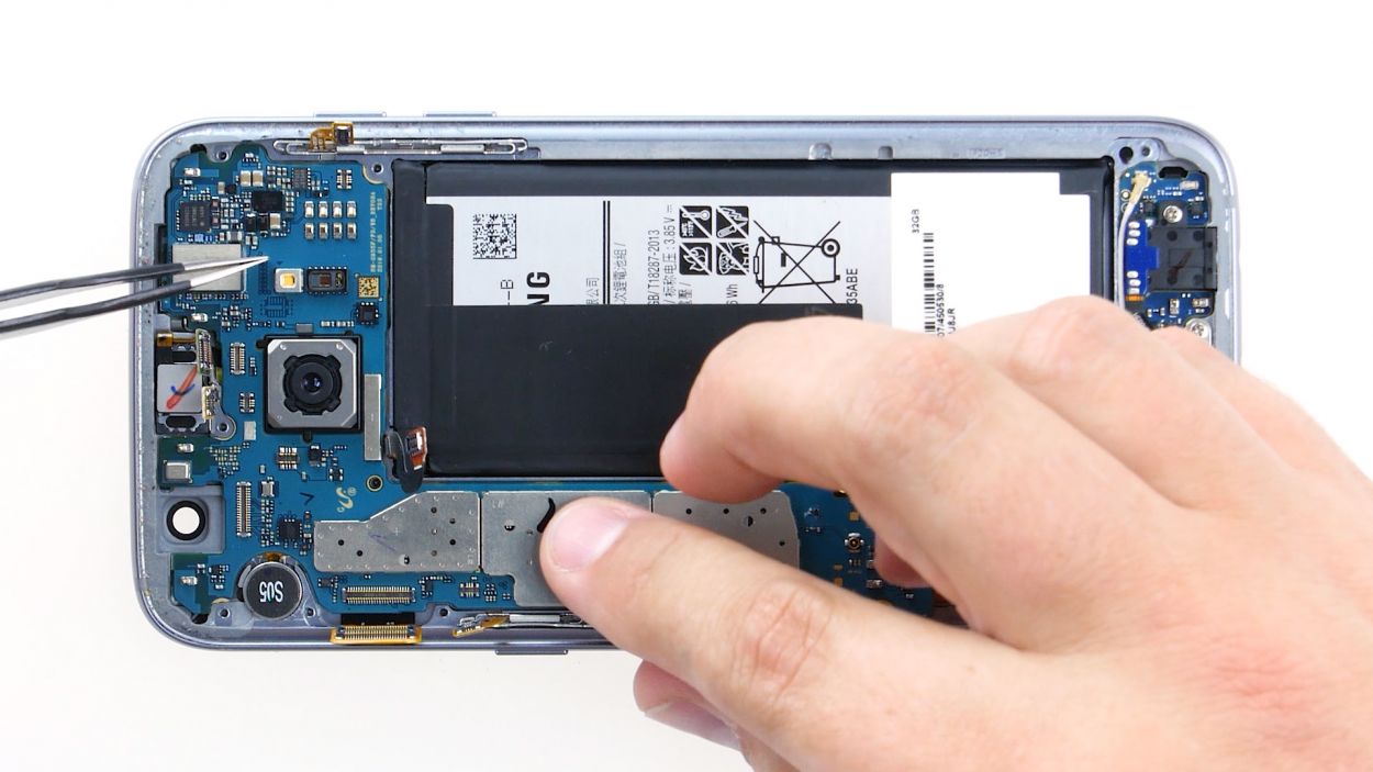
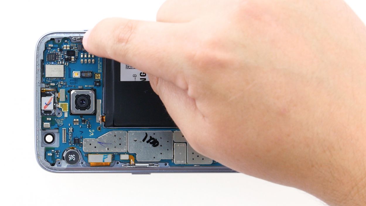
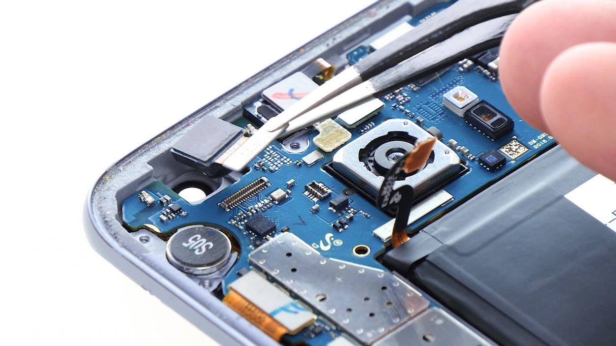
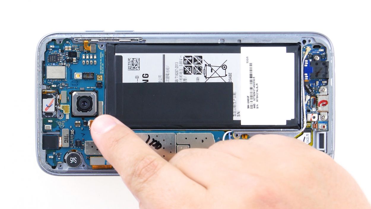
– With your trusty spudger in hand, gently pry away those pesky contacts from the motherboard. You’ve got this!
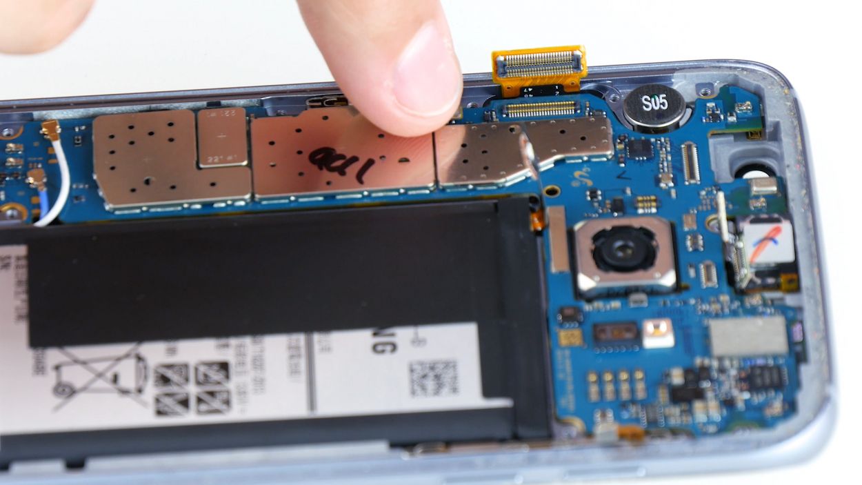
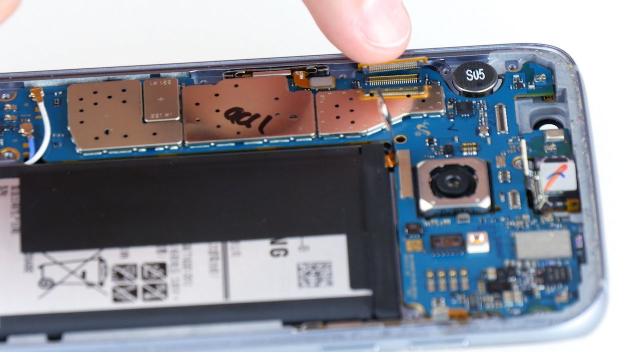
Step 11
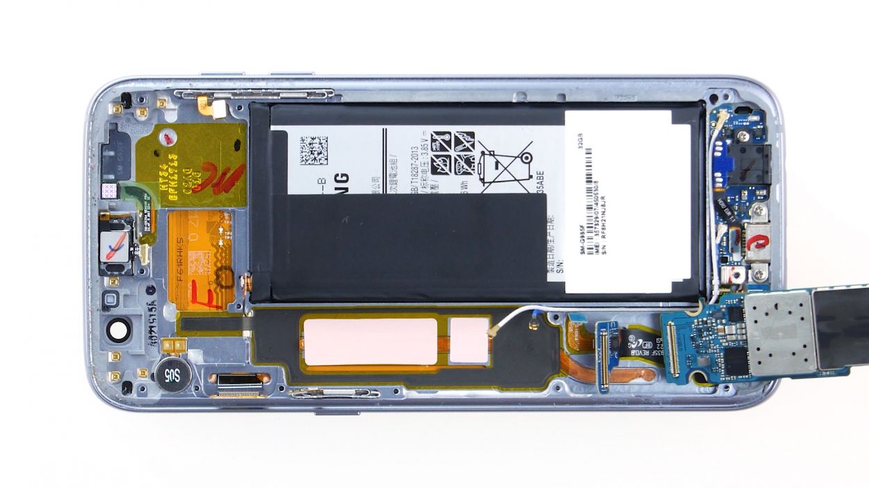
Hey there! Just a heads up: there’s a tiny plastic pin hanging out in the SIM tray opening. Make sure it stays put, or it might just decide to take a little vacation!
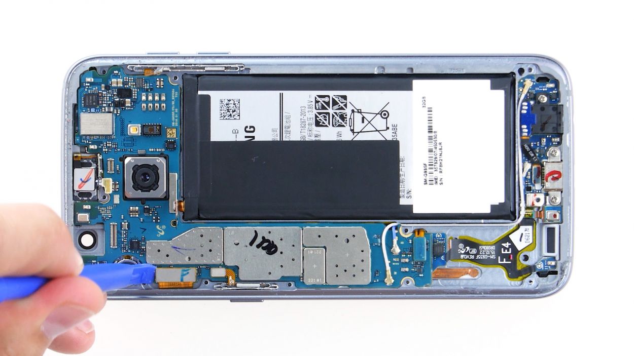
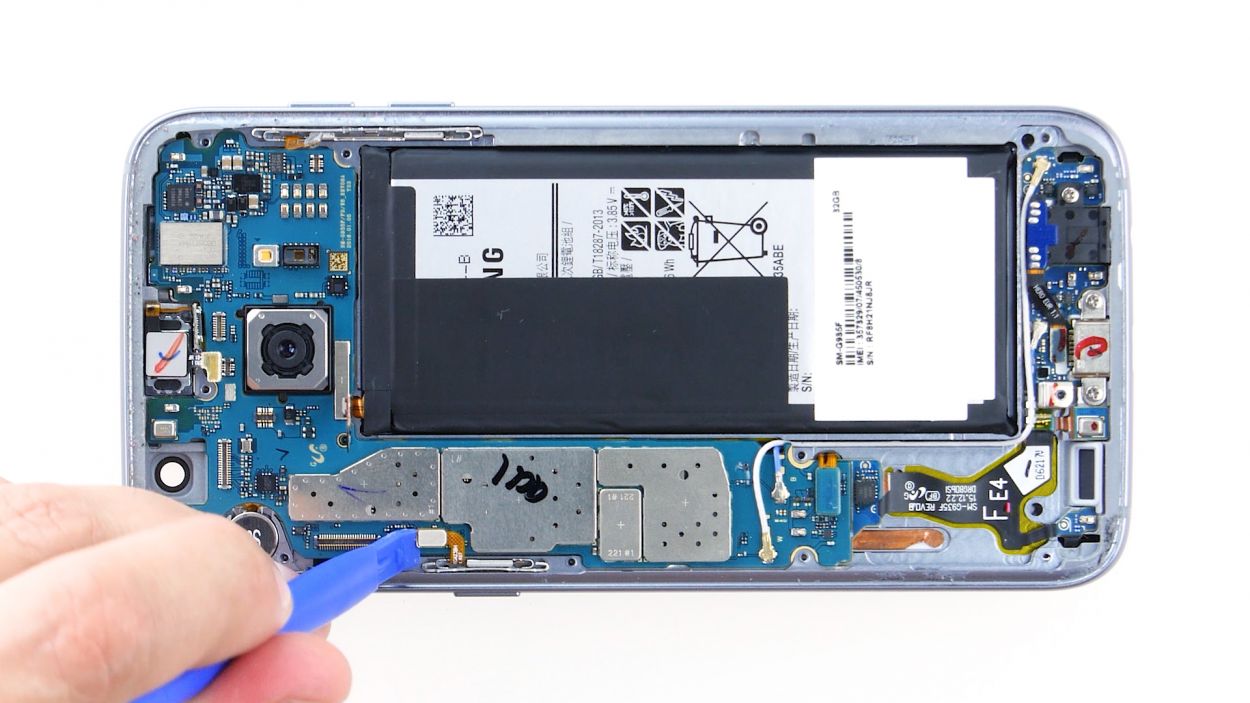
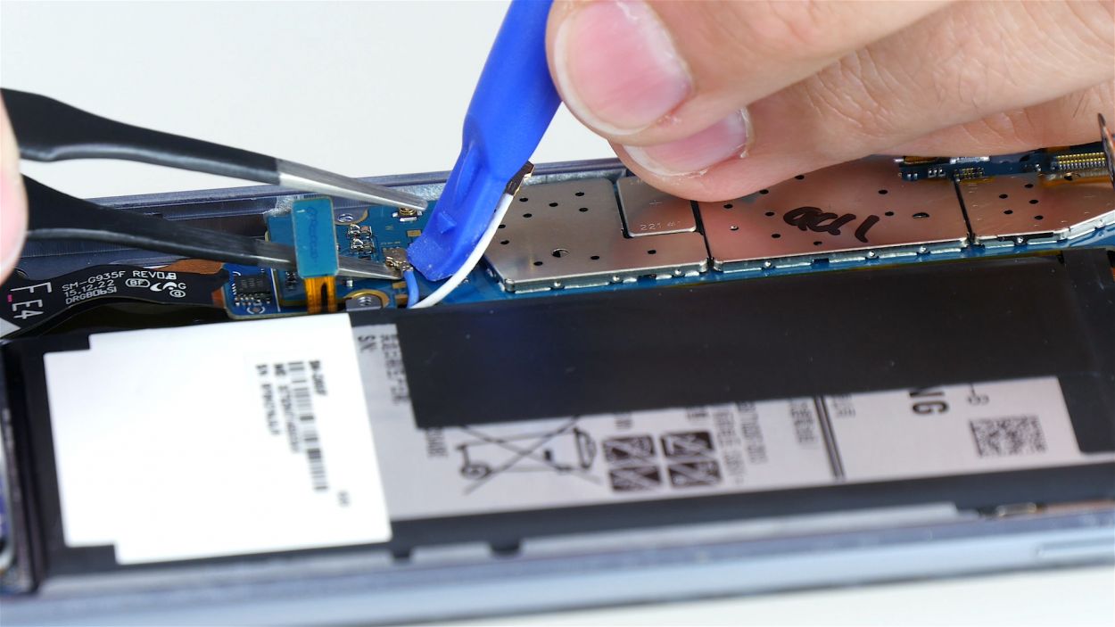
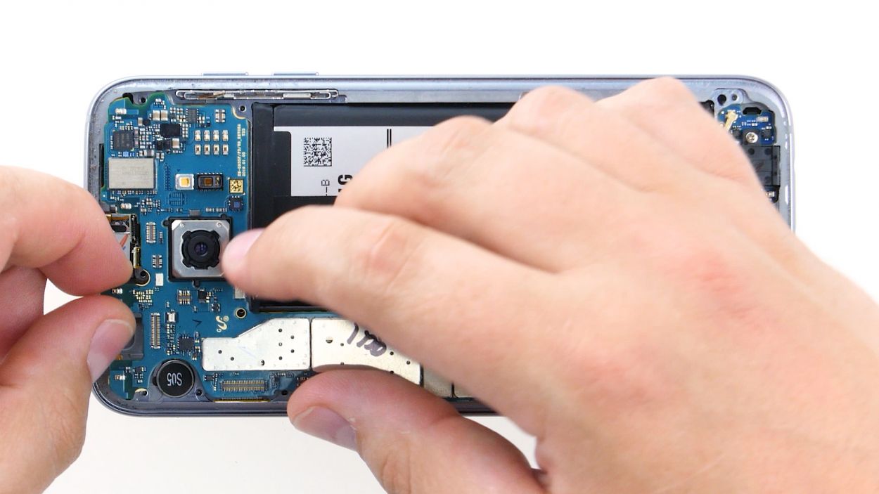
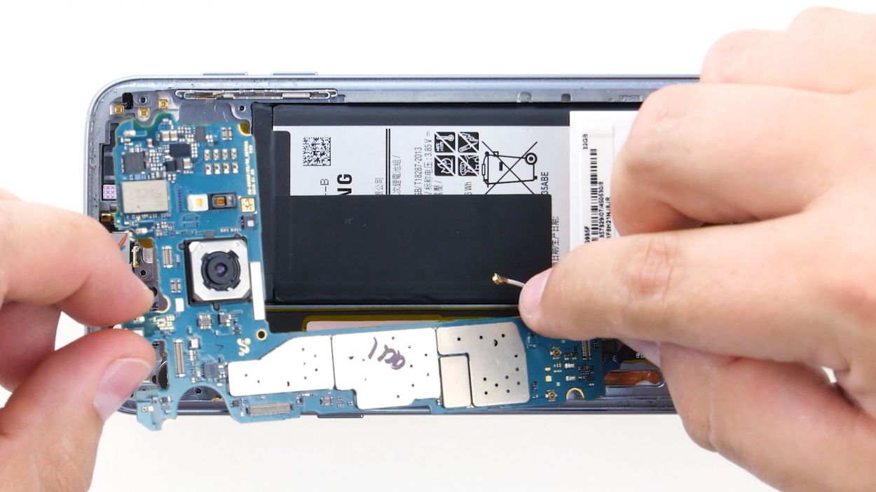
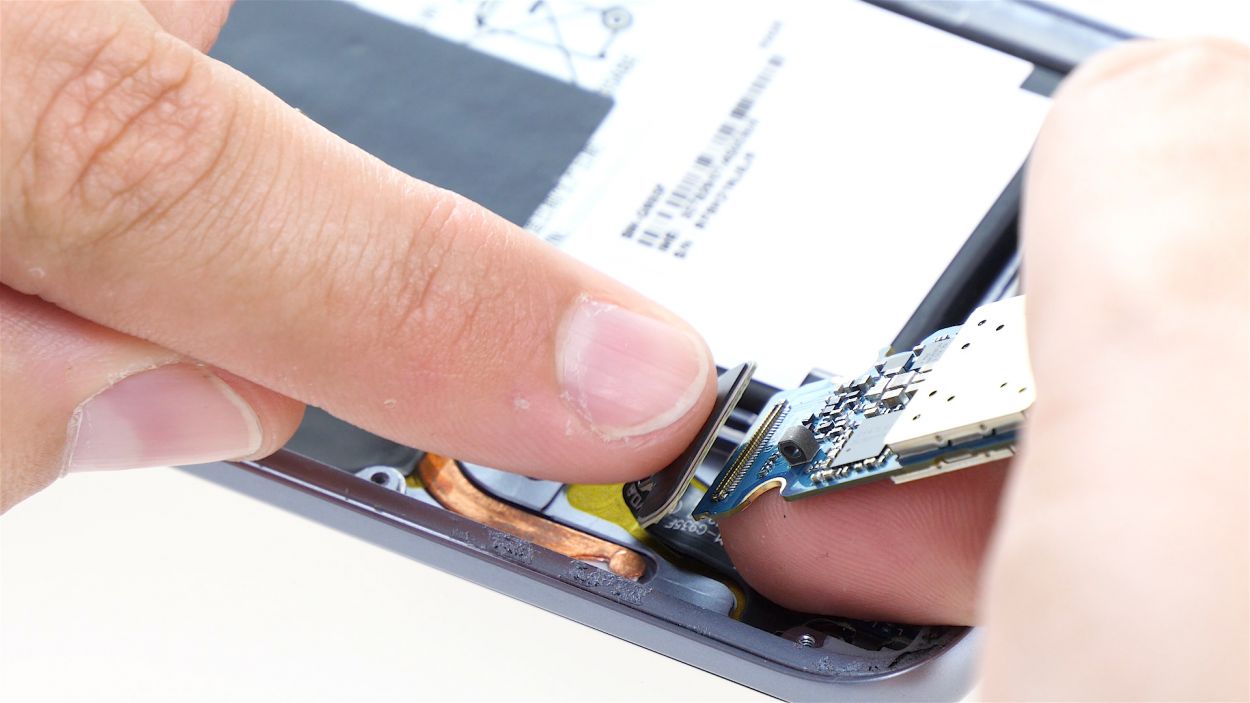
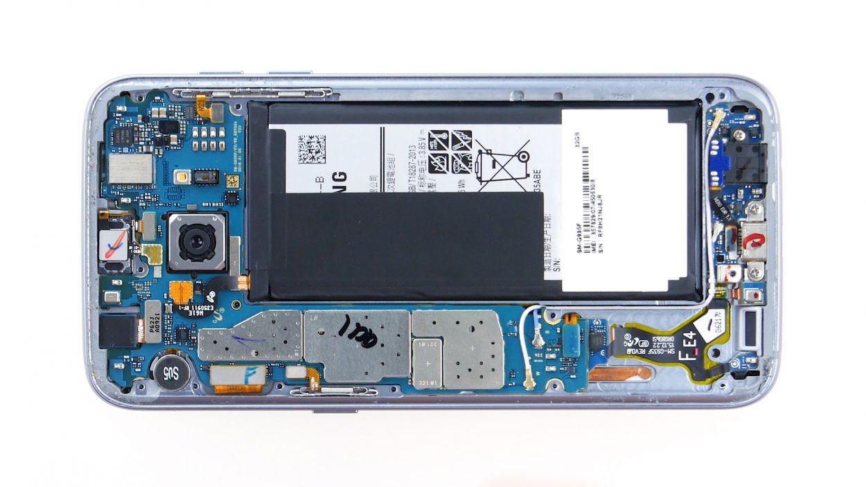
– Guess what? The bottom of the motherboard (pointy arrow) is actually best buddies with the USB port.
– Time to show some love! Gently tilt the board by 180° to reach the contact. Remember, don’t go Hulk on the board.
– Grab your spudger and perform a magic trick – disconnect the contact from the PCB with finesse.
– Adios, board! Remove it like a pro.
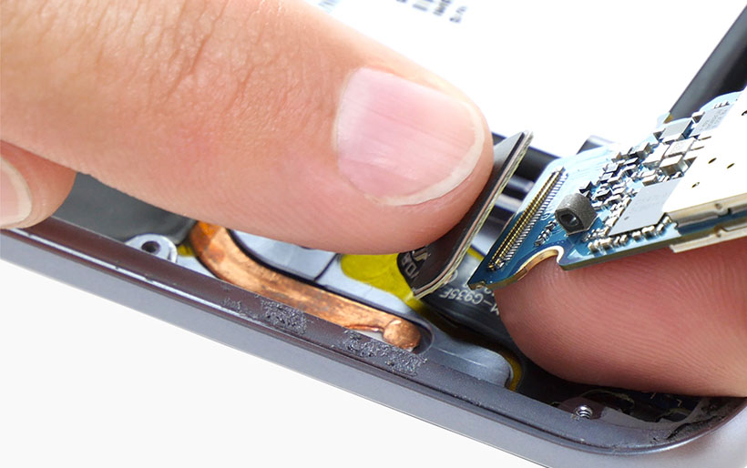
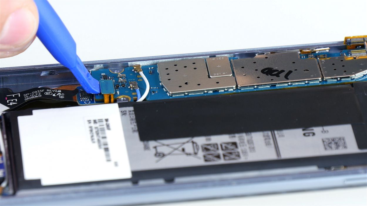
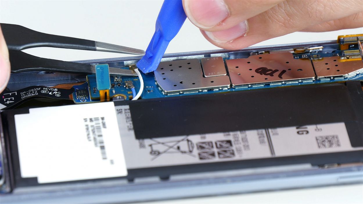
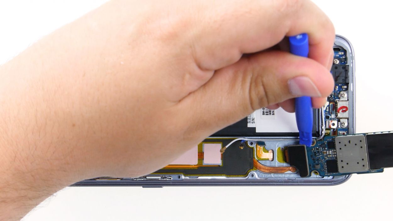
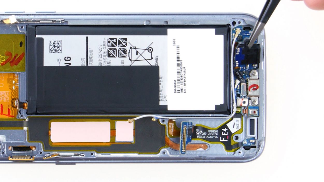
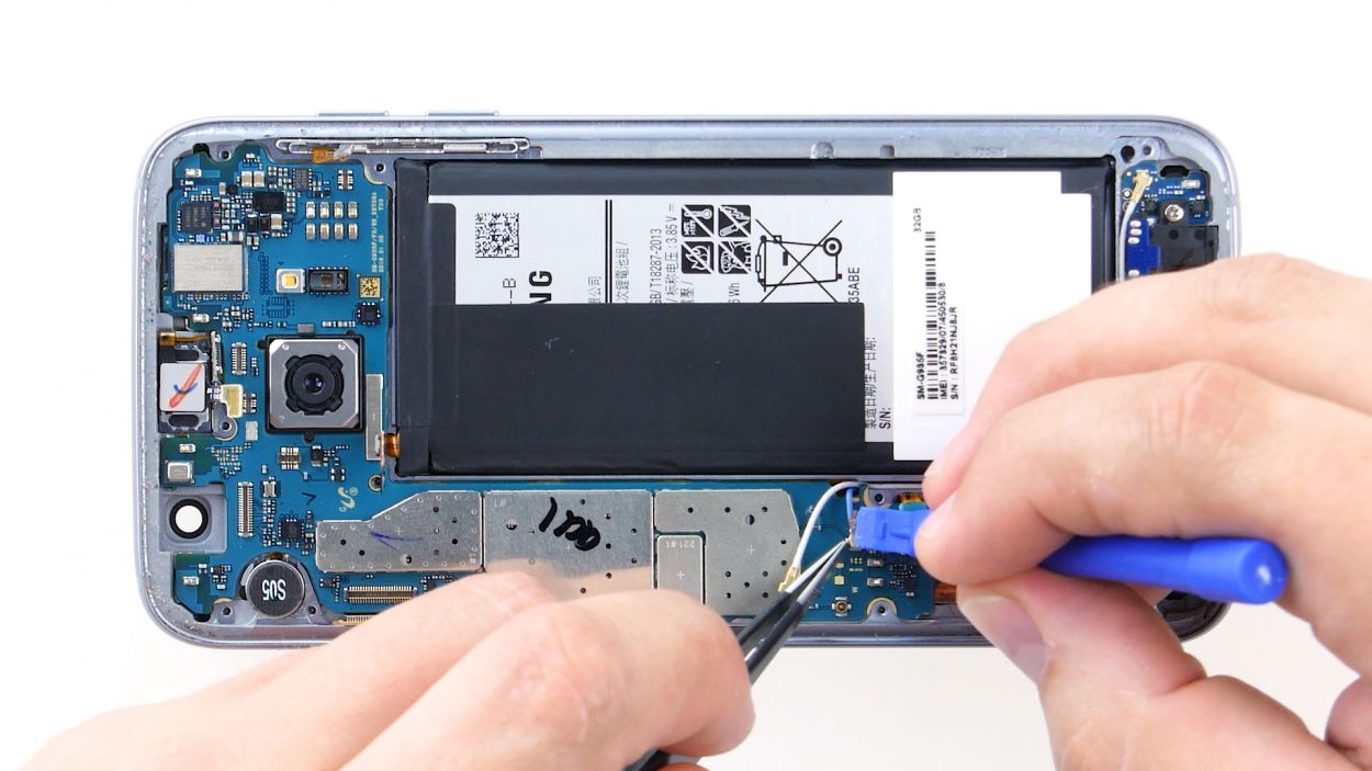
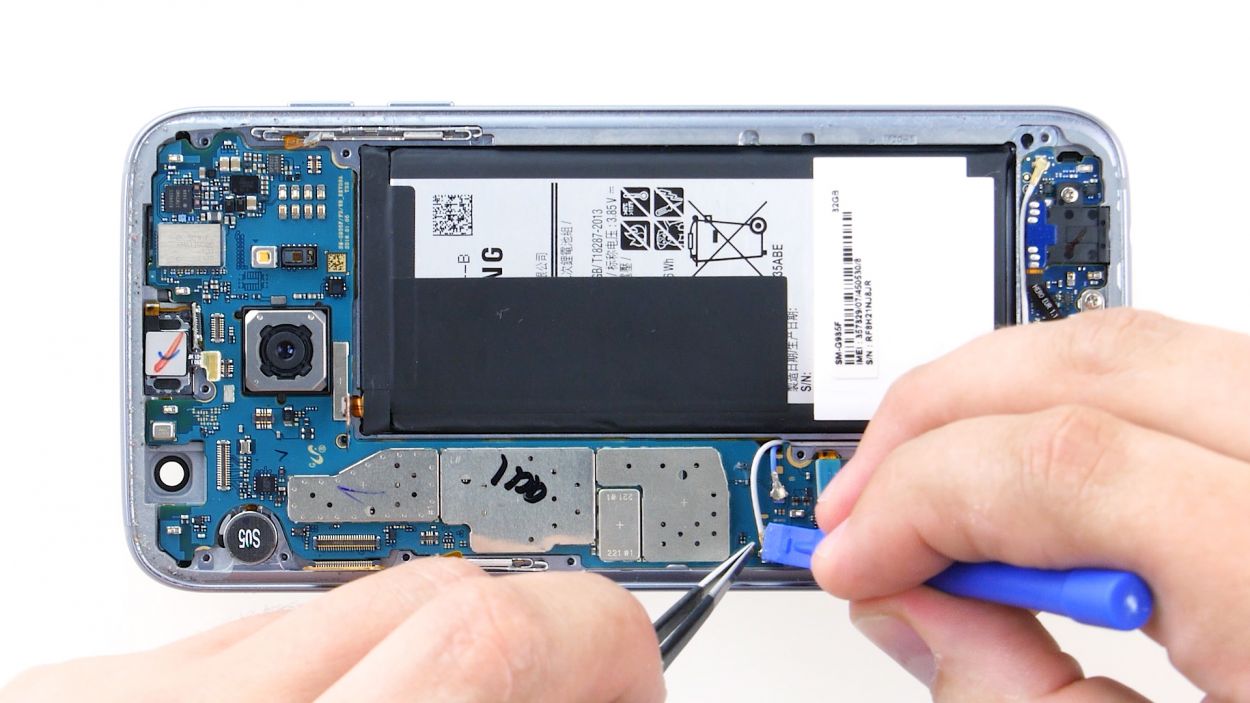
Step 12
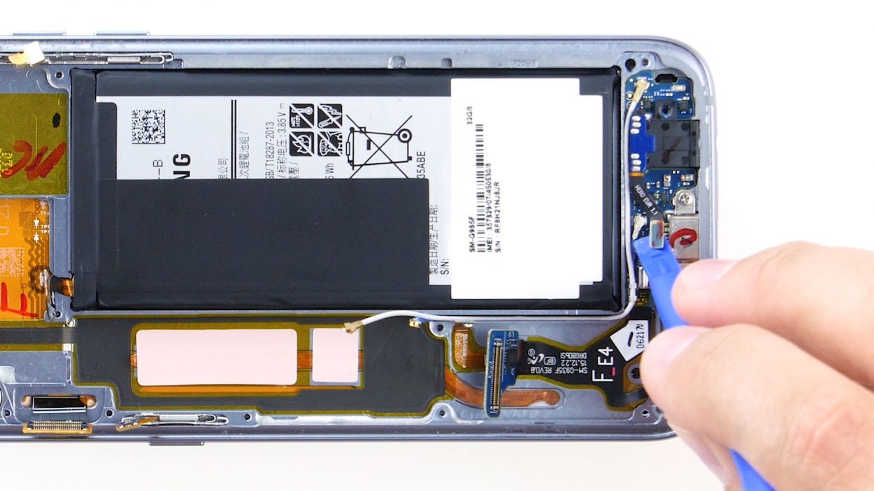
1 × 3,3mm PH00 Phillips-Schraube
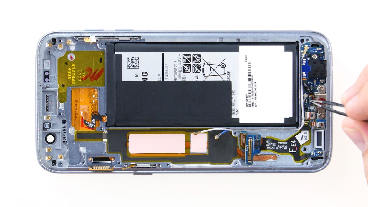
– First things first, gently disconnect the headphone jack’s contact from the PCB. Grab your trusty spudger and carefully wiggle that contact out of its cozy socket.
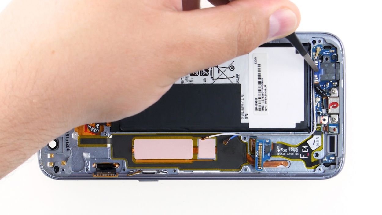
– Next up, it’s time to unscrew the little guy holding everything together. Remove that 1 x 3.3 mm PH00 Phillips screw with ease.
– Finally, give a gentle tug and remove the headphone jack from its enclosure. You’re doing great!
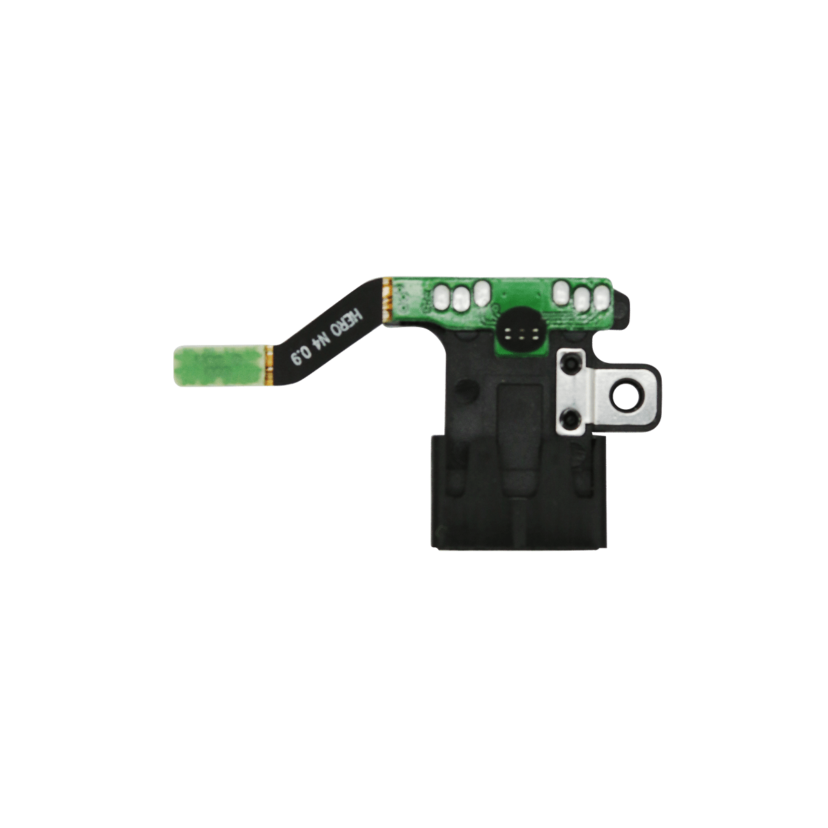
Step 13

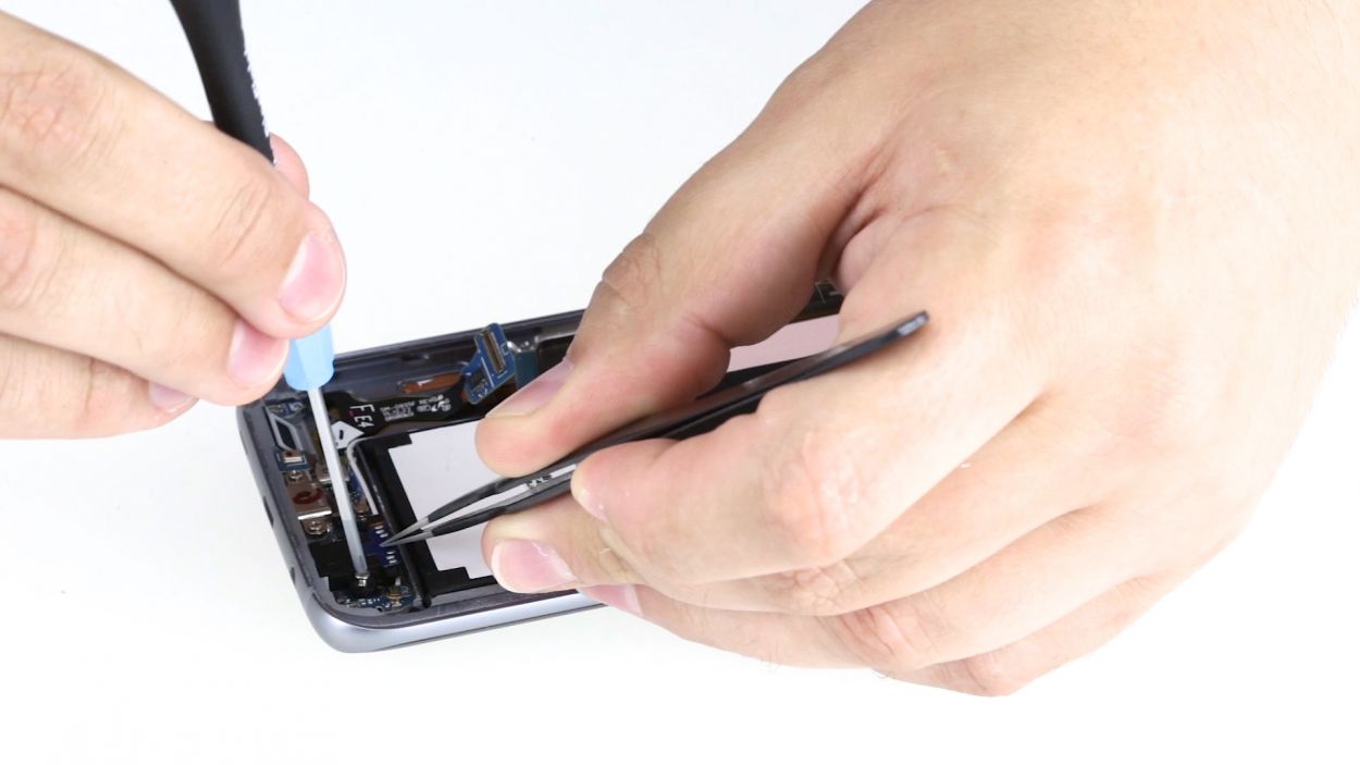
1 × 3,3mm PH00 Phillips-Schraube
– Slide that jack right into the cozy little spot on the bottom edge of the enclosure.
– Grab a screw and fasten that jack securely to the enclosure.
– Connect the jack’s contact to the PCB. Listen for that satisfying click; it means you did it right!
Step 14

– Flip the board over and gently place it at the bottom of the enclosure to reconnect the USB port’s contact.
– Make sure to connect the contact until you hear that satisfying click as it locks into place.
– Now, fold the board over and tuck it back into the enclosure snugly.
Step 15

Proximity Sensor
Earpiece Connector
Display
Power-Button
Antenna
Sensors
Volume Connector
– Connect the contacts to the motherboard.
Step 16
– Slide that front camera into its cozy little spot at the top edge of the enclosure.
– Give the camera a gentle nudge to connect it to the motherboard. Listen for that satisfying click as it locks into place!
Step 17
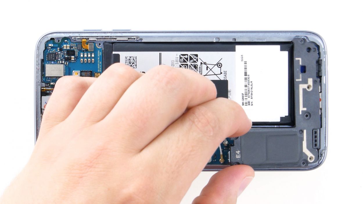
– Plug that battery into the motherboard! Just press it down into the socket until you hear a satisfying click. You’ve got this!
Step 18

– Slide that antenna right into the lower part of the enclosure.
– Give it a gentle press with your fingers until you hear that satisfying click, letting you know it’s snug in place.
Step 19
– Carefully slide the antenna back into the enclosure after attaching it to the lower antenna. You’re almost there!
– Give that antenna a gentle press with your fingers until you hear that satisfying click confirming it’s snug in place.
Step 20
– Slide that antenna back into its cozy home! Start by placing it on the left side and then give it a firm press with your fingers to secure it.
– Listen closely for that satisfying click as the antenna locks into place!
Step 21


12 × 3,3mm PH00 Phillips-Schrauben
– Time to stick that yellow adhesive strip back on like a champ!
– Now, grab those three antennas and secure them in place with the twelve screws—12 x 3.3 mm PH00 Phillips screws to be exact. You’ve got this!
Step 22
– Carefully place the back cover back where it belongs.
– Give the back cover a gentle press all around to help the glue do its job.
– For an extra boost, warm up your device with some hot air, then use a clamp or stack a couple of books on it to help the glue stick even better.