How To Replace Samsung Galaxy S8 Active I/O Daughterboard Guide
Duration: 45 minutes
Steps: 24 Steps
Hey there! Don’t forget to be extra cautious while doing this step. We don’t want any boo-boos during your fix-up session, alright? If you need help, you can always schedule a repair.
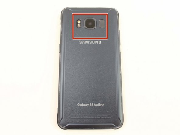
Hey there! Ready to tackle repairing your Samsung Galaxy S8 Active? Let’s dive in and swap out that I/O Daughterboard. You might need to do this if your USB-C connector or microphone is acting up. Don’t worry, we’ll start by popping off the back cover – just make sure to have some replacement adhesive handy for sticking it back on. And hey, before you get started, remember to check that battery level – we don’t want any fiery surprises! Keeping it below 25% will help keep things cool. If you’re feeling stuck, don’t fret! You can always schedule a repair for some expert assistance.
Step 1


– Time to get that SIM card out! Grab your trusty SIM card ejector tool (or a straightened paperclip will do) and gently poke it into the tiny hole on the left side of the top edge of your phone.
– Give it a gentle press to pop the SIM tray right out.
– Now, carefully pull the SIM card tray out of your device.
– When you’re ready to put the SIM card tray back, make sure the gold contacts are facing up and the notch is in the bottom right corner. Just press the SIM card gently back into the slot of the tray.
Step 2


– Using your trusty TR6 Torx Security Screwdriver, take out those four black 3mm screws from the outer edges of your device that are holding the rubber bumpers in place.
– Gently remove the rubber bumpers from both the top and bottom edges of the device. If you need help, you can always schedule a repair.
Taking off the back cover of the S8 Active will mess with its waterproofing. Make sure you have some replacement adhesive ready before you start, or keep it away from water if you don’t plan on replacing the adhesive when you put it back together. If you need help, you can always schedule a repair.
Tools Used

Step 3

Watch out! When using a heat gun, hair dryer, or hot plate, that metal frame can get pretty toasty, so be sure to give it a gentle touch.
Keep an eye on the heat – too much can be a bad thing for the OLED display, battery, and other internal components. Aiming for about a minute should do the trick to loosen up that adhesive.
You can also heat up the edges using an iFixit iOpener, a hair dryer, or even a hot plate. Get them warmed up and ready to go!
– Grab a heat gun and gently warm up the edges of the back cover to loosen the adhesive holding it in place.
Tools Used

Step 4


– Gently slide your trusty Jimmy tool under the edge of the back cover, like you’re tucking a blanket in.
– Once the Jimmy tool is snugly in place, pop an opening pick into the seam. This will keep things open and prevent any slip-ups if the Jimmy decides to take a vacation.
– Take your time and cut carefully around the top section of the device. Watch out for those sneaky cables for the fingerprint sensor and camera. Remember, we want to keep that fingerprint sensor happy, so don’t pry too deep!
– Now, glide the Jimmy tool down the sides of the device, effortlessly separating that adhesive like a pro.
Tools Used

Step 5

Hey there! The fingerprint sensor cable hangs out at the top of your phone, right by the front-facing camera. To keep that cable safe and sound, gently take off the back cover—no need to rush it!
– Use the opening pick to carefully slice through any remaining sticky stuff.
– Pop the back cover open just enough so you can spot the fingerprint sensor flex cable connector.
Step 6


– Carefully flip the cover over and gently place it on top of the device like a cozy blanket.
– Use the flat end of a spudger to delicately disconnect the fingerprint flex cable, giving it a little nudge.
– Time to remove the back cover, just lift it off with a bit of flair.
– When you’re putting the fingerprint sensor cable back together, tilt the back cover just right so the flex cable can snuggle into its socket. Then, with the flat end of the spudger, give it a gentle push straight down to secure it in place.
Tools Used

Step 7


– Get rid of those eleven pesky 3.5 mm screws by putting your trusty Phillips #00 Screwdriver to work.
– Bid farewell to those two tiny 2mm screws using your reliable Phillips #00 Screwdriver.
Tools Used

Step 8


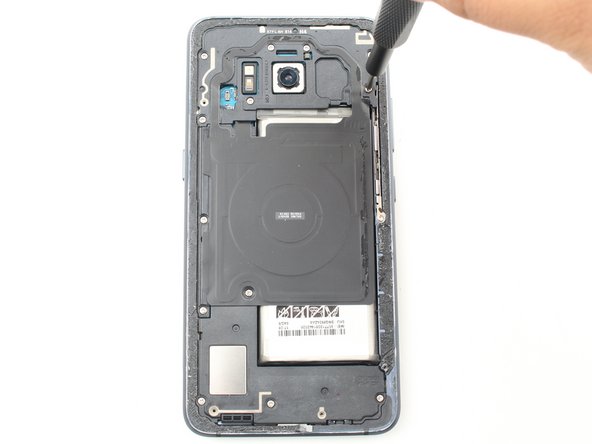
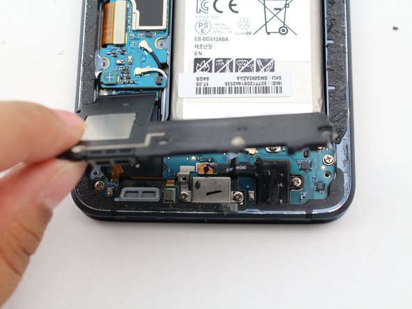
– Gently pry off the NFC antenna and charging coil assembly with the flat end of a spudger. You’ve got this!
Tools Used


Step 11


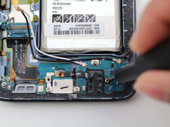
– Gently unplug the headphone jack flex cable using the flat end of a spudger. You’ve got this!
Tools Used
Step 12

– Grab your trusty Phillips #00 Screwdriver and slide it into the headphone jack chilling at the bottom edge of your device.
– With a gentle touch, guide the screwdriver upwards, granting freedom to the headphone jack.
Tools Used


Step 14

– Safely unscrew that pesky 3.5 mm screw with your trusty Phillips #00 Screwdriver. You’ve got this!
Tools Used
Step 15


– Gently detach the Volume Up, Volume Down, and Bixby button flex cable using the flat end of your trusty spudger. You’ve got this!
Tools Used

Step 17


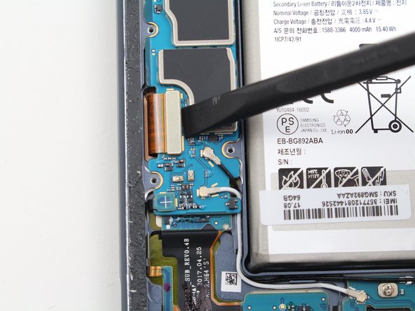
– Unlock the charging port flex cable using the flat end of a spudger with a touch of finesse.
Tools Used

Step 19

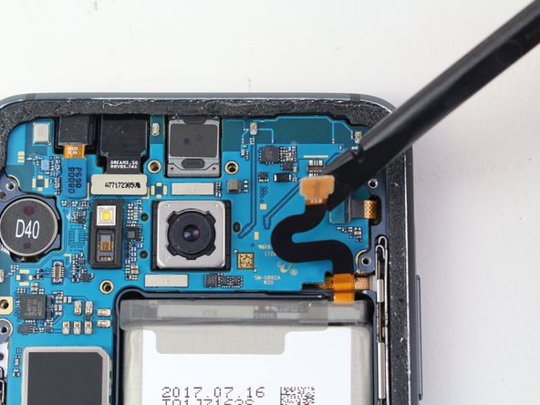
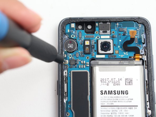
– Time to work some magic! The motherboard and the daughterboard are like best friends chilling together, connected by a flex cable. Get your spudger ready and gently disconnect this stylish cable that’s keeping them attached. It’s like giving them some space to breathe!
Tools Used
Step 20


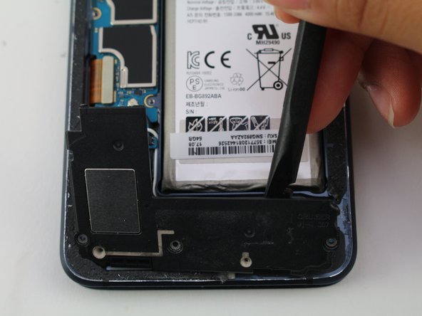
– Get ready to rock and roll by placing the flat end of a spudger at the top edge of the motherboard.
– Show that motherboard who’s boss! Gently lift up and bid it farewell.
Tools Used
Step 21


– Grab your trusty Philips #00 screwdriver and get ready to tackle this! Start by removing five of those pesky 3.5 mm screws. You’ve got this!
Step 22

– Get down with it! Use the flat end of a spudger to disco the black and white cellular antennas.
Tools Used
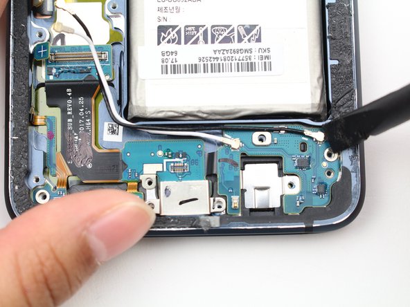
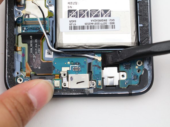
Step 23

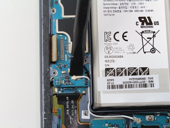
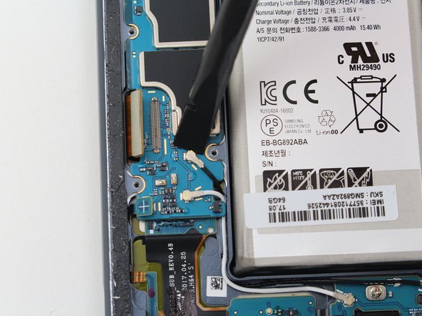
The flex cable is gently stuck to the device’s frame with a dab of adhesive. Just give it a little love and it’ll come off without a hitch!
– Pop off that flex cable that hooks up the charging port to the motherboard. Just slide the flat end of your spudger in there.
Tools Used