How to Replace Sony Xperia Z2 Screen Tutorial
Duration: 60 min.
Steps: 26 Steps
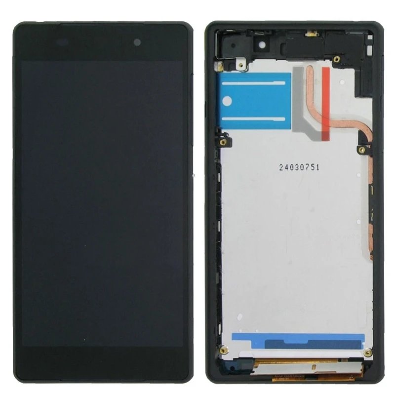
In this guide, we’re going to walk you through the steps to replace the display unit of your Sony Xperia Z2. If you’re dealing with a cracked glass, an unresponsive touchscreen, or an LCD that’s as dark as night or flickering like a disco ball, then you’ve come to the right place! Let’s get your device looking and working like new again. And hey, if you need help along the way, feel free to schedule a repair.
Step 1
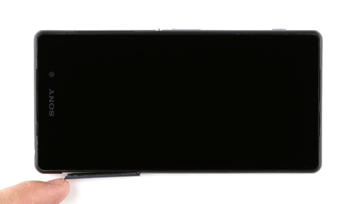

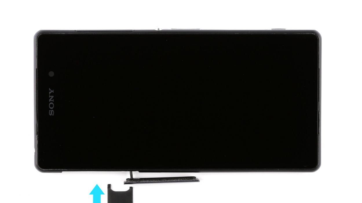
– Hey there! The SIM card slot is cleverly tucked away under a cover on the left side of your Xperia Z2. To get it open, just use your fingernail or a flat, pointy tool like a steel spatula. Slide your finger or the tool under the top edge of the cover and give it a gentle tug to pop it off.
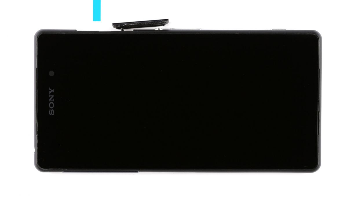
– This cover is pretty flexible and can spin 360°. Swing it open to access the SIM card tray. There’s a little tab on the tray that you can easily pull with your fingernail or some tweezers.
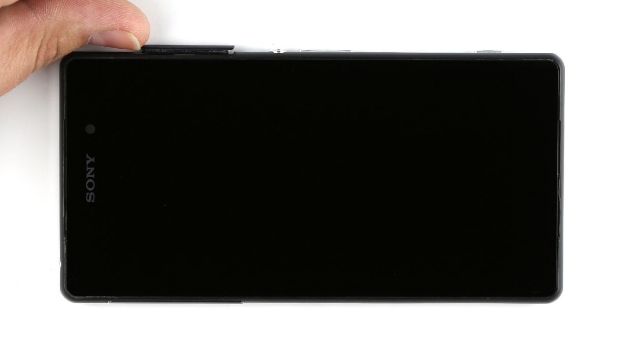
– Now, let’s not forget about the microSD card, which is also hiding under a cover, this time on the right side of the Xperia Z2. Just open it up like you did for the SIM card.
– Go ahead and remove the microSD card. You’ll find a little indentation on the card that’s perfect for pulling it out with your fingernail or tweezers.
– Once you’ve got everything sorted, don’t forget to close both covers again to make the next steps a breeze!
Step 2
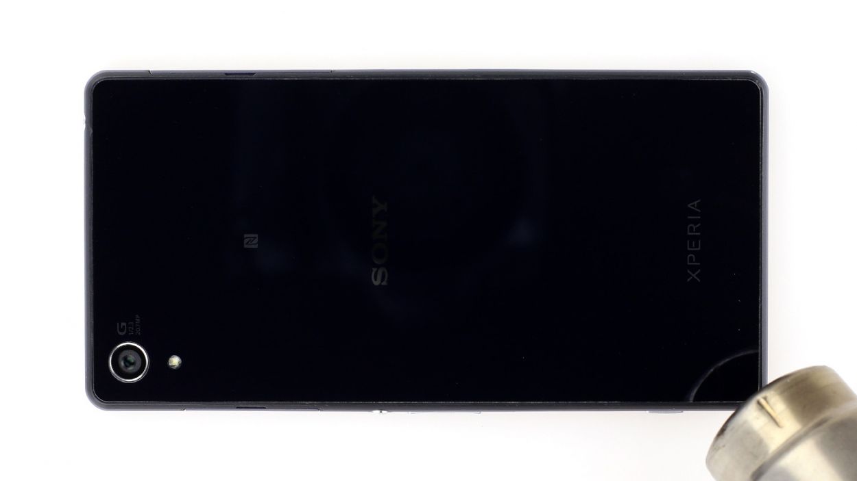
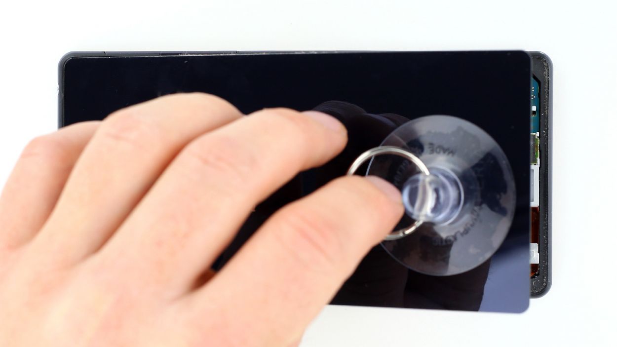
– The back cover of your Sony Xperia Z2 is stuck on there like a stubborn sticker! To free it, grab a heat gun and warm it up a bit to soften that adhesive. Then, slide a plastic pick into the tiny gap between the frame and the glass to gently peel it away.
– That gap between the aluminum frame and the glass is pretty tight, so make sure to use a nice flat and sturdy tool to help you get in there.
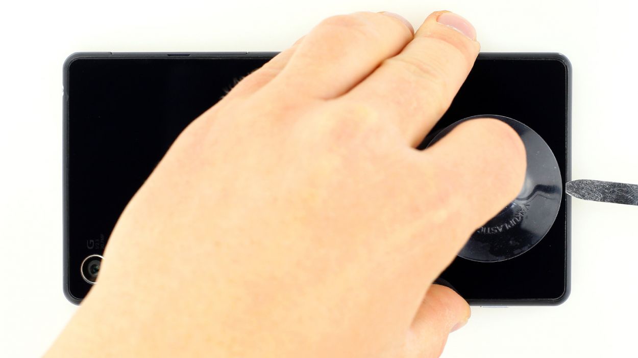
– With a suction cup in hand, carefully lift the back cover. You’ve got this!
– Once you’ve opened up a little space, use that plastic pick to keep the aluminum safe from any mishaps.
Step 3
The back cover has a stylish coat on the inside! Take your time removing any sticky bits to keep it looking sharp and crack-free.
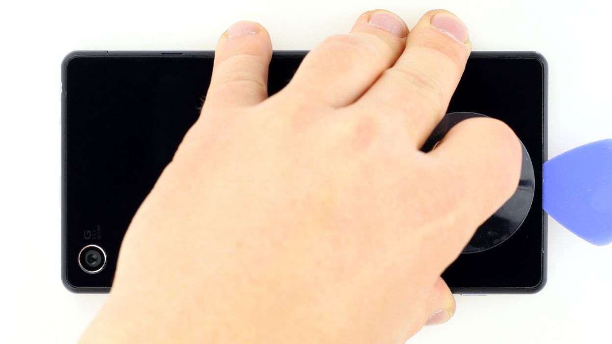
– Gently slide the pick just a few millimeters between the back cover and the frame. We want to keep the inner workings safe and sound! Remember, the inside of the back cover is painted, so be careful as you remove any adhesive residue to avoid scratches or cracks.
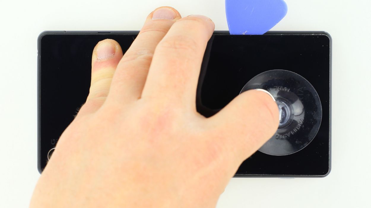
– The back cover of the Sony Xperia Z2 is glued all around the outer edge, so take your pick and make a smooth journey around the entire phone.
– Once you’ve successfully loosened all that glue, you can carefully lift off the back cover and reveal the magic inside!
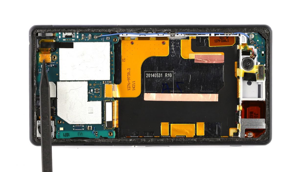
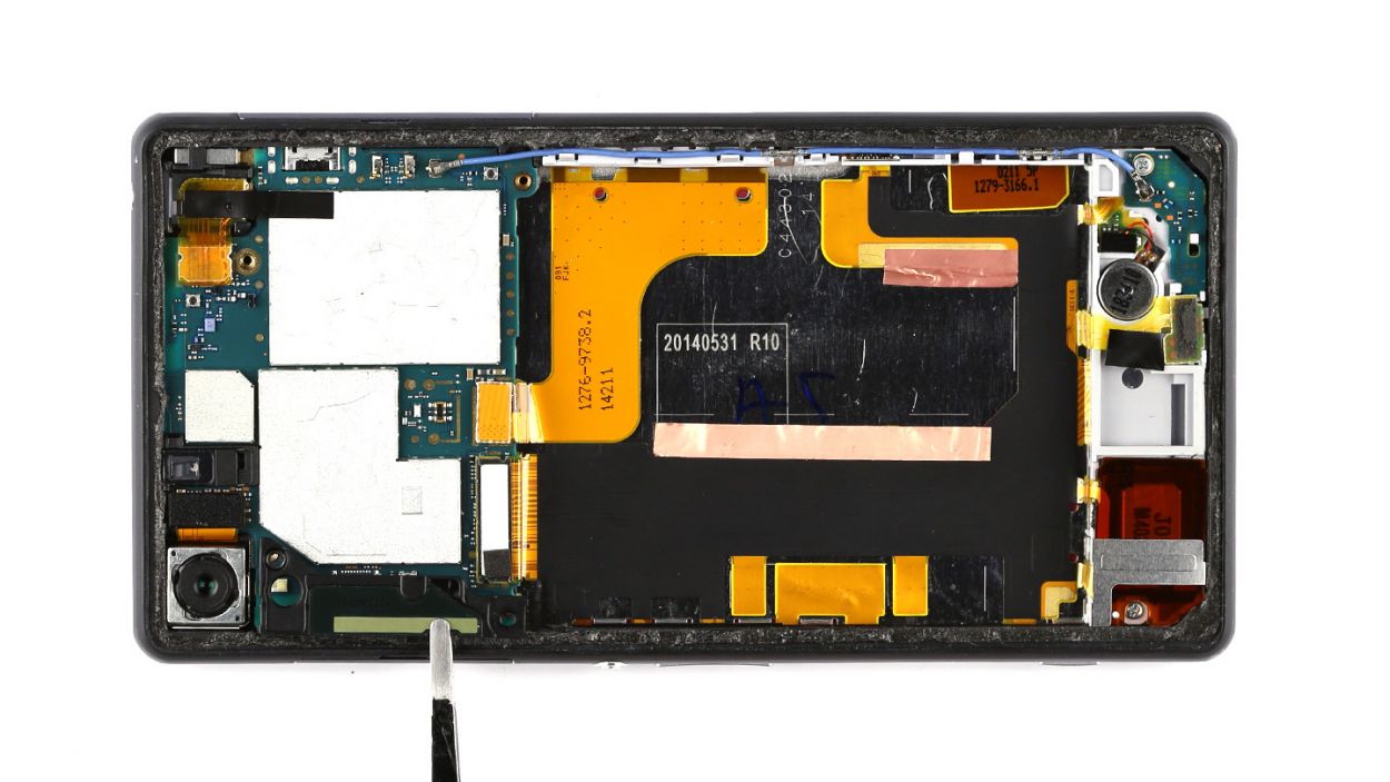
Step 4
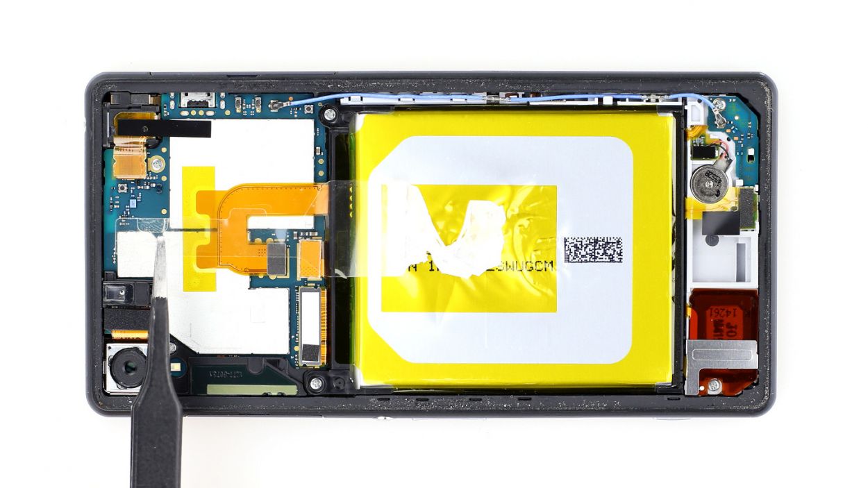


– First up, let’s peel off that clear plastic strip covering the battery connection cable. Easy peasy!
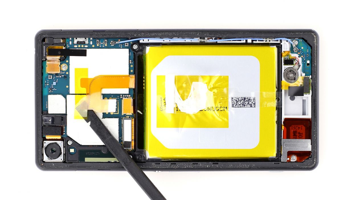
– Next, take the flat end of your spudger and gently slide it just below the contact. Give it a little lift, but be careful not to disturb those tiny resistors soldered onto the logic board.
– Now, it’s time to detach the cable set from the silver plate. It’s just a bit glued down, so a little finesse will do the trick.
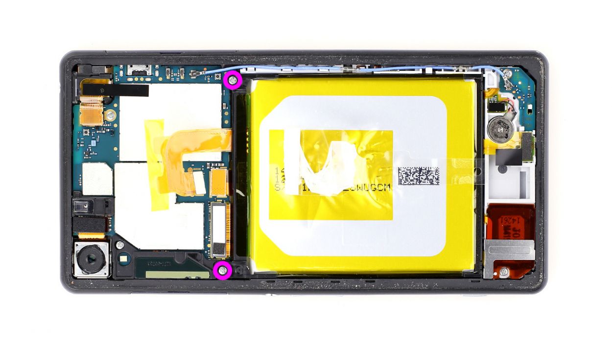
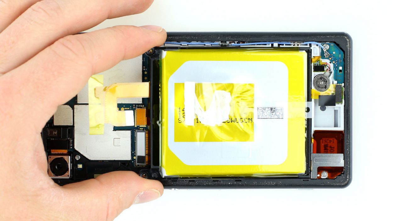
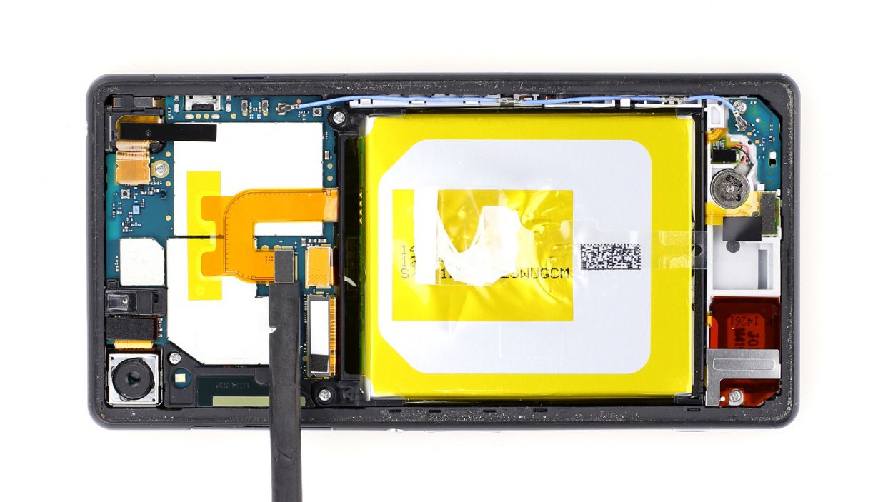
– Remove those two Phillips screws—2 x 3.3 mm Phillips screws to be exact. You’ve got this!
– Finally, go ahead and take out the battery. You’re making great progress!
Step 5
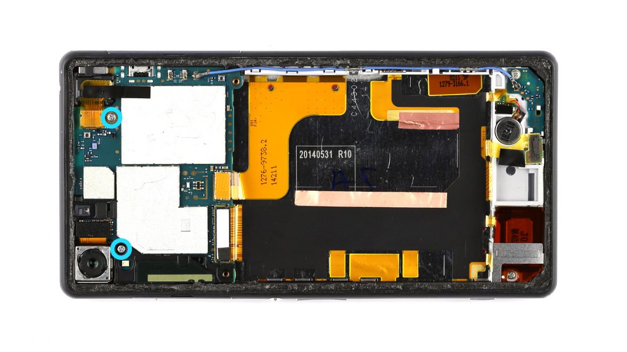

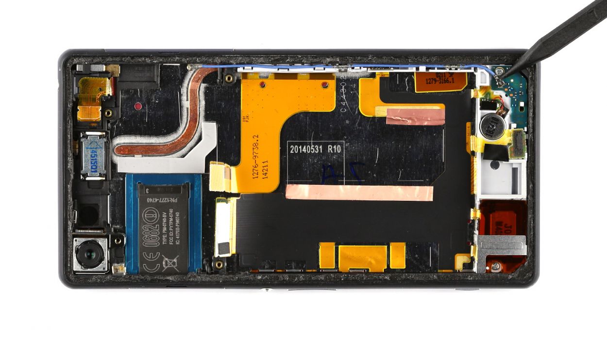
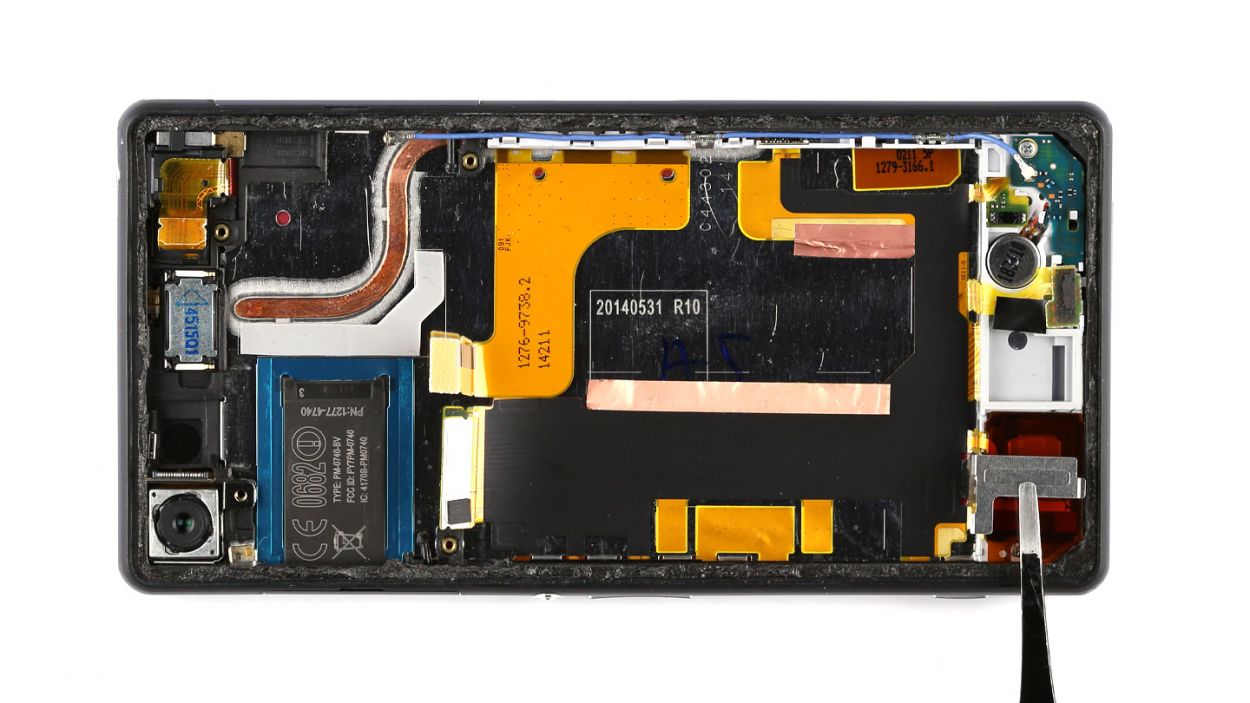
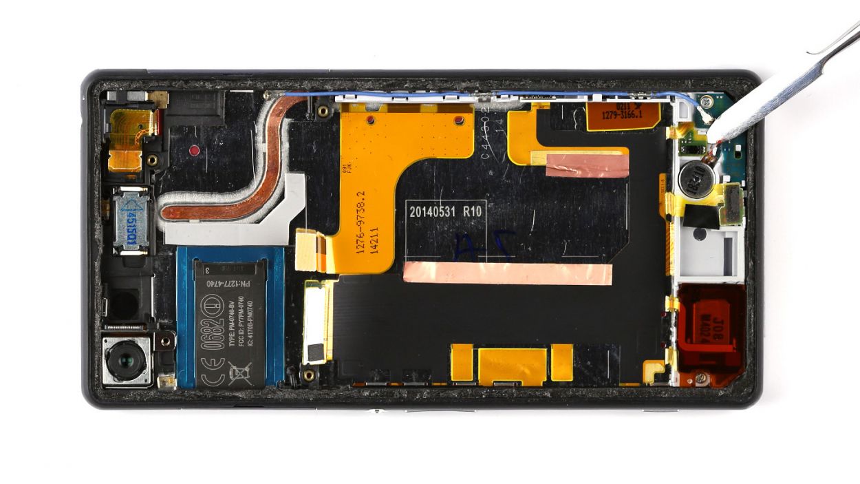
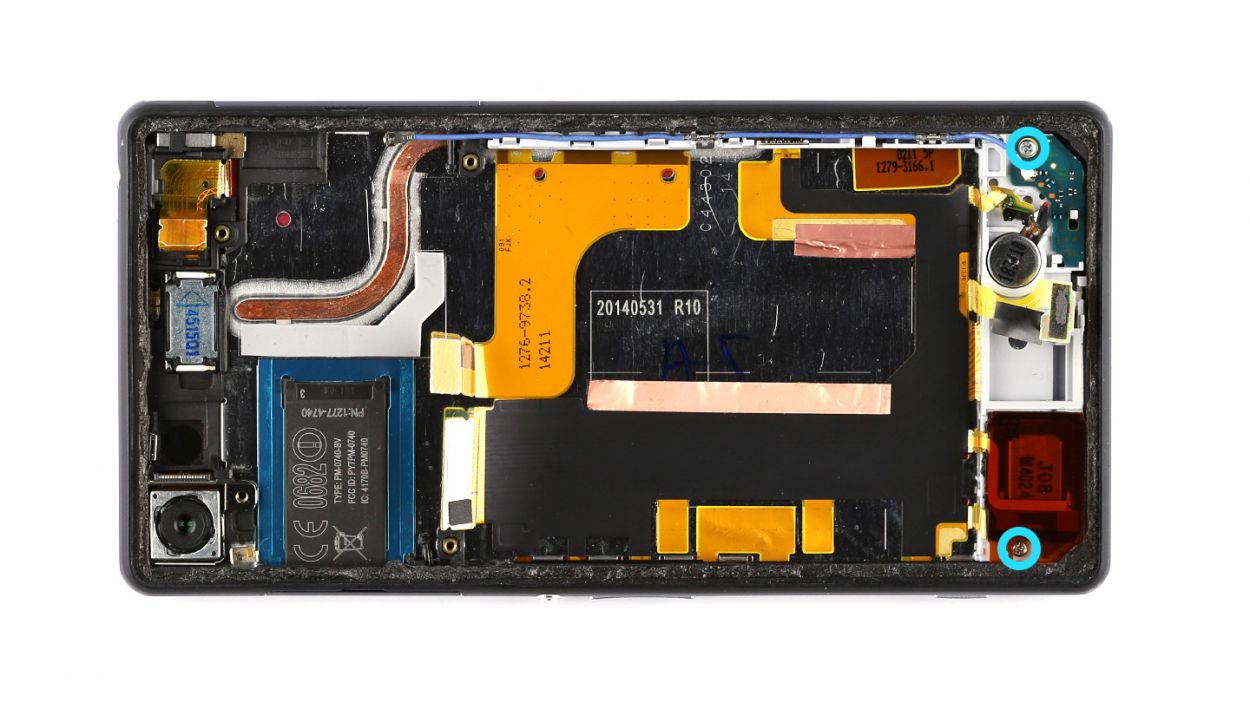
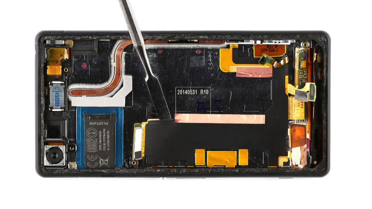
– Unscrew those two Phillips screws holding the logic board in place. They’re 2 x 3.4 mm, so grab your trusty screwdriver and let’s get to it!
– With a gentle touch, use a pair of tweezers to carefully lift out the black antenna. Treat it like the delicate little flower it is!
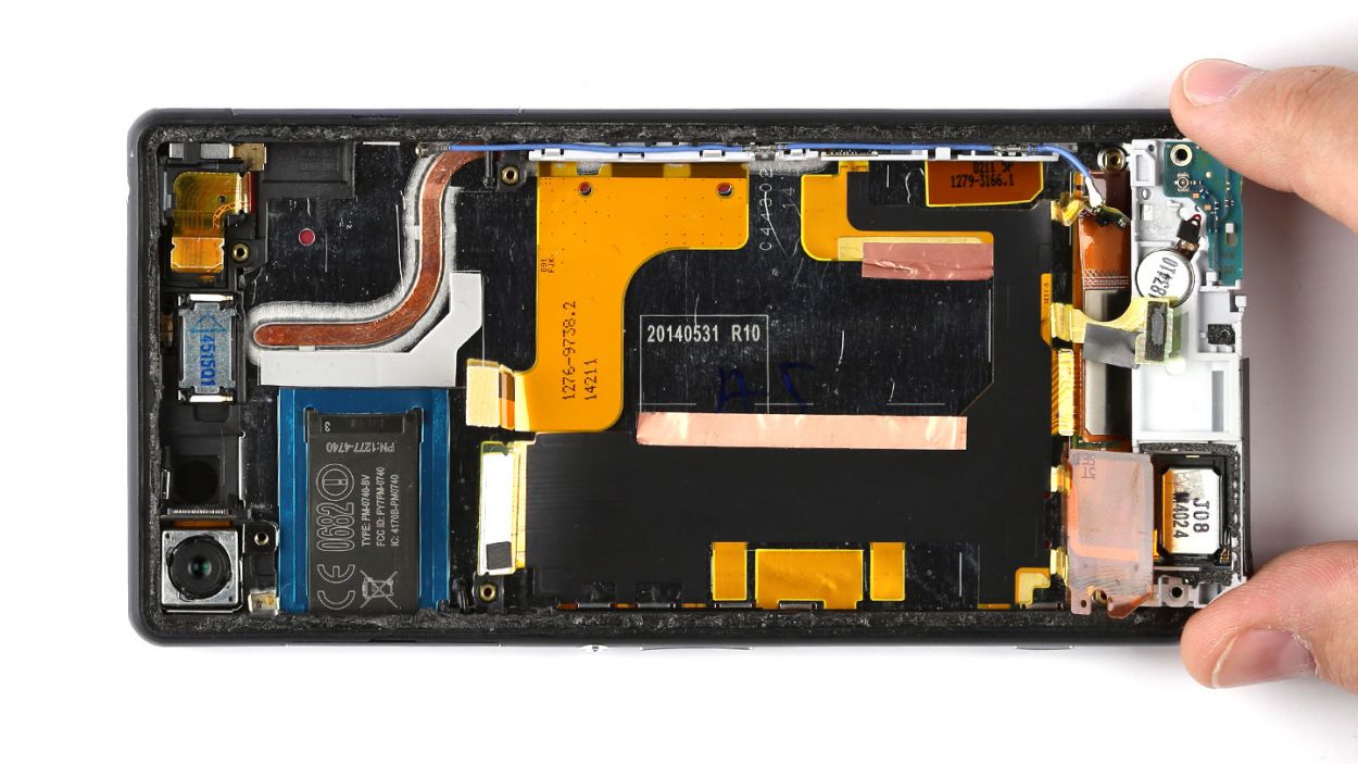
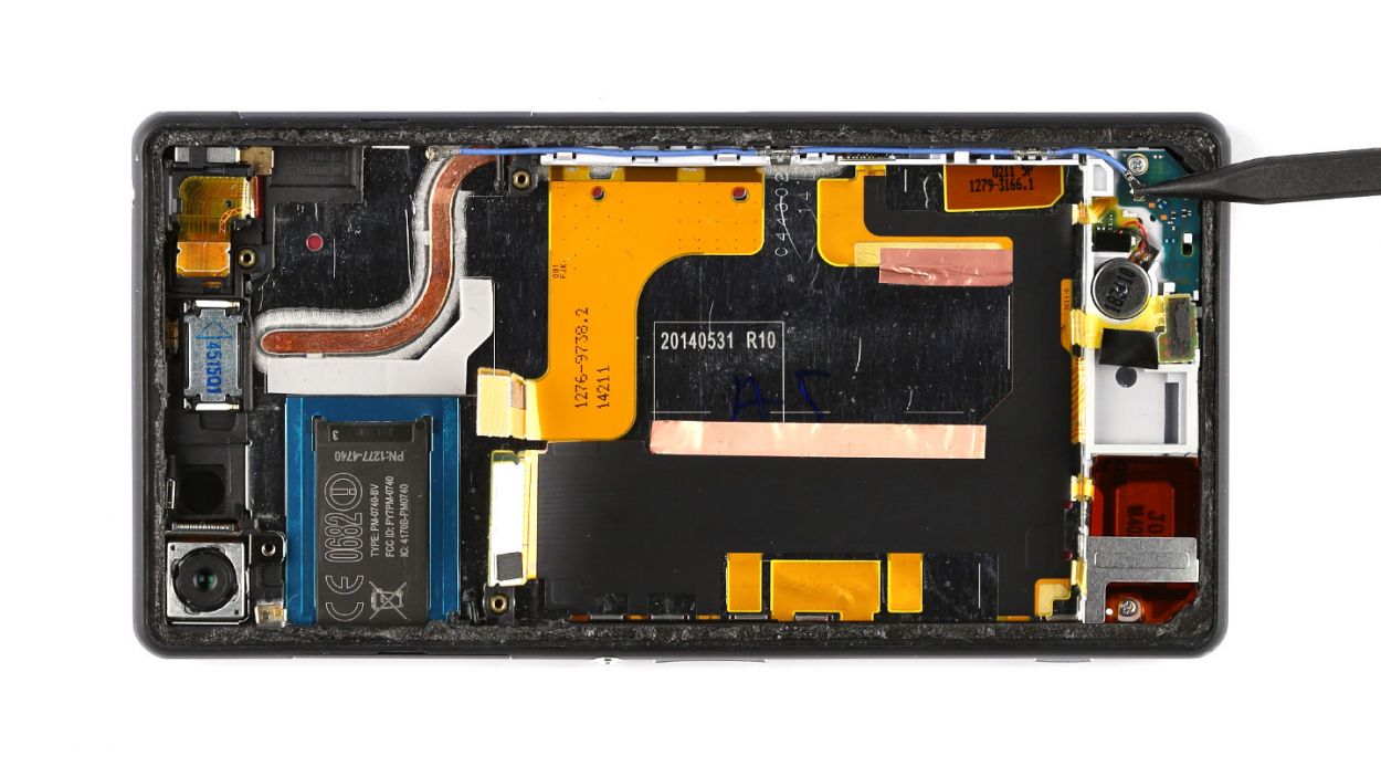
Step 6


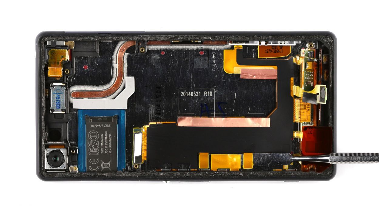
– Gently detach the 3.5 mm jack socket from the logic board by carefully prying off the connector with your trusty spudger.
– Unplug the antenna cable that links the logic board to the sub-board.
– Carefully pop the charging port’s connector off the logic board.
– Disconnect the connector for the control buttons with a gentle touch.
– Unplug the connection between the logic board and the rear camera.
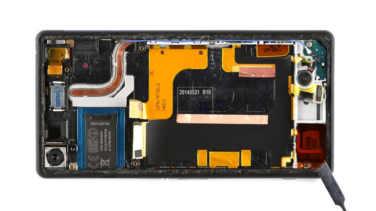
Step 7
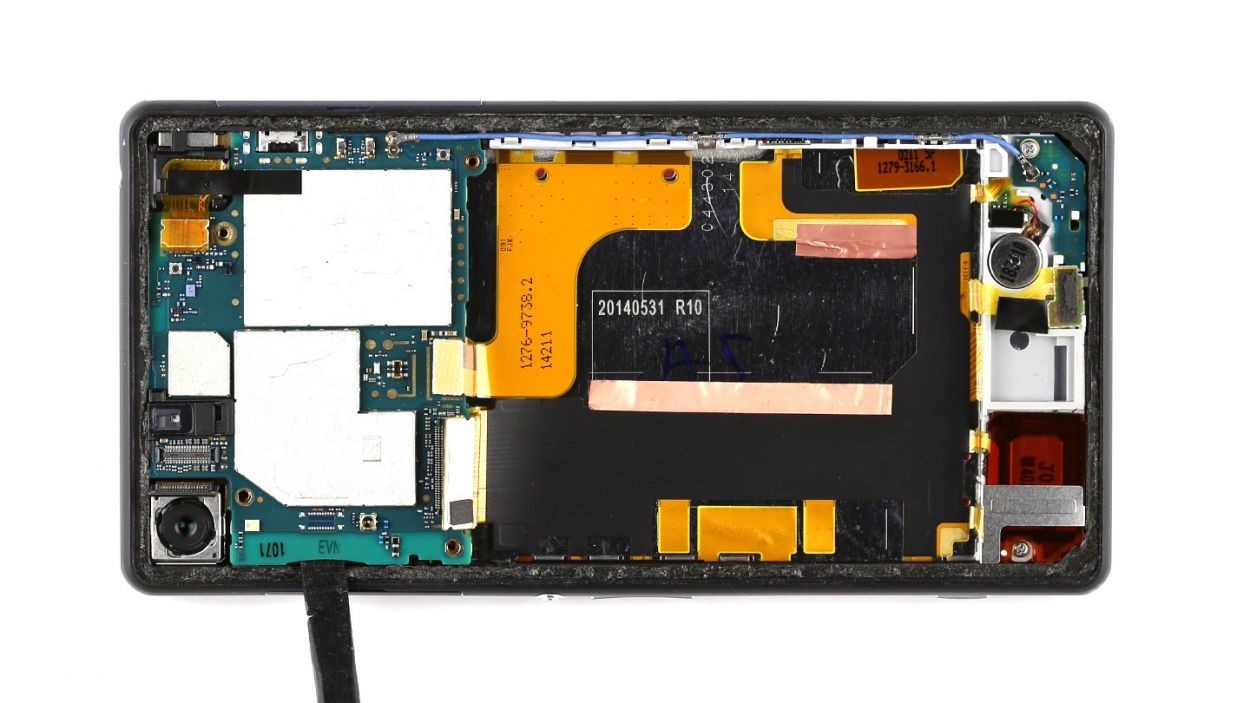
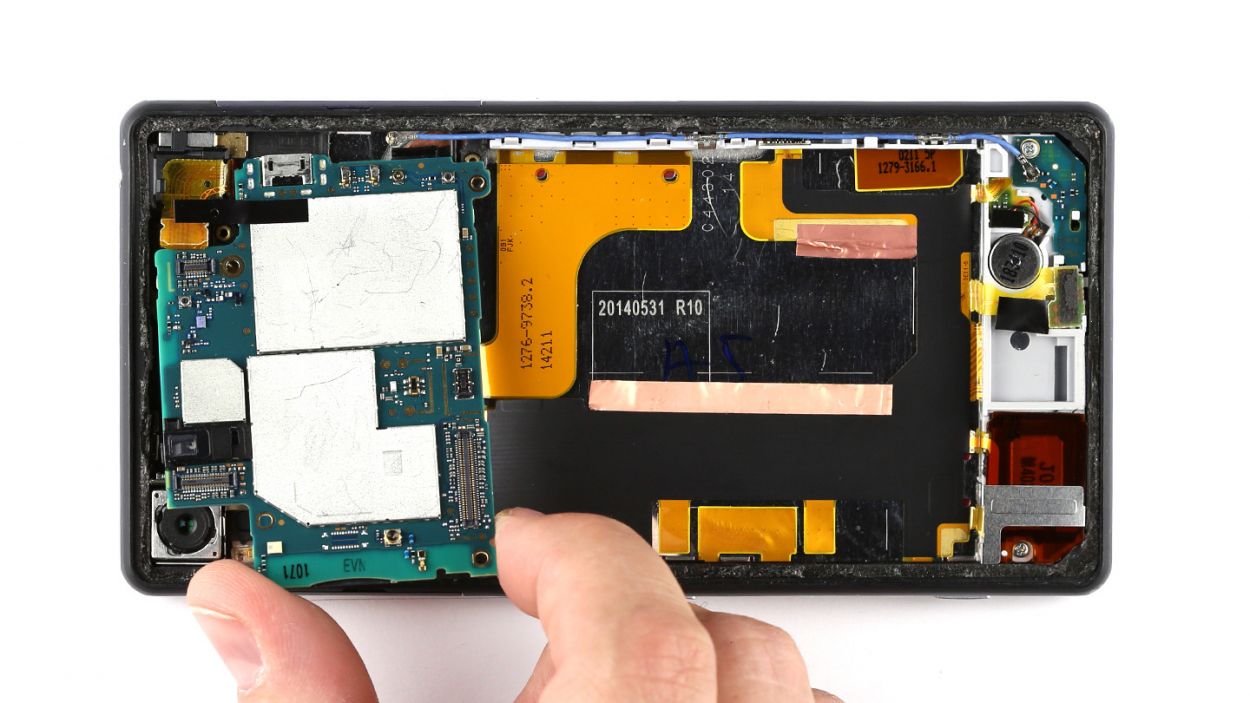
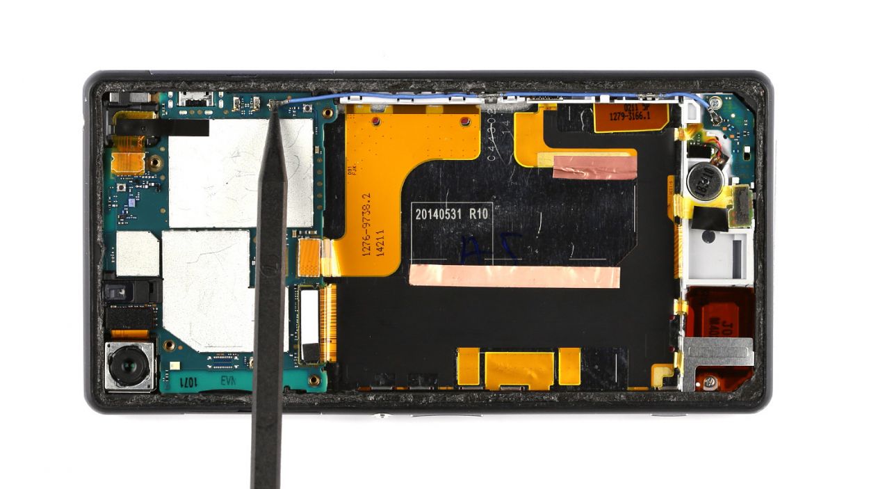
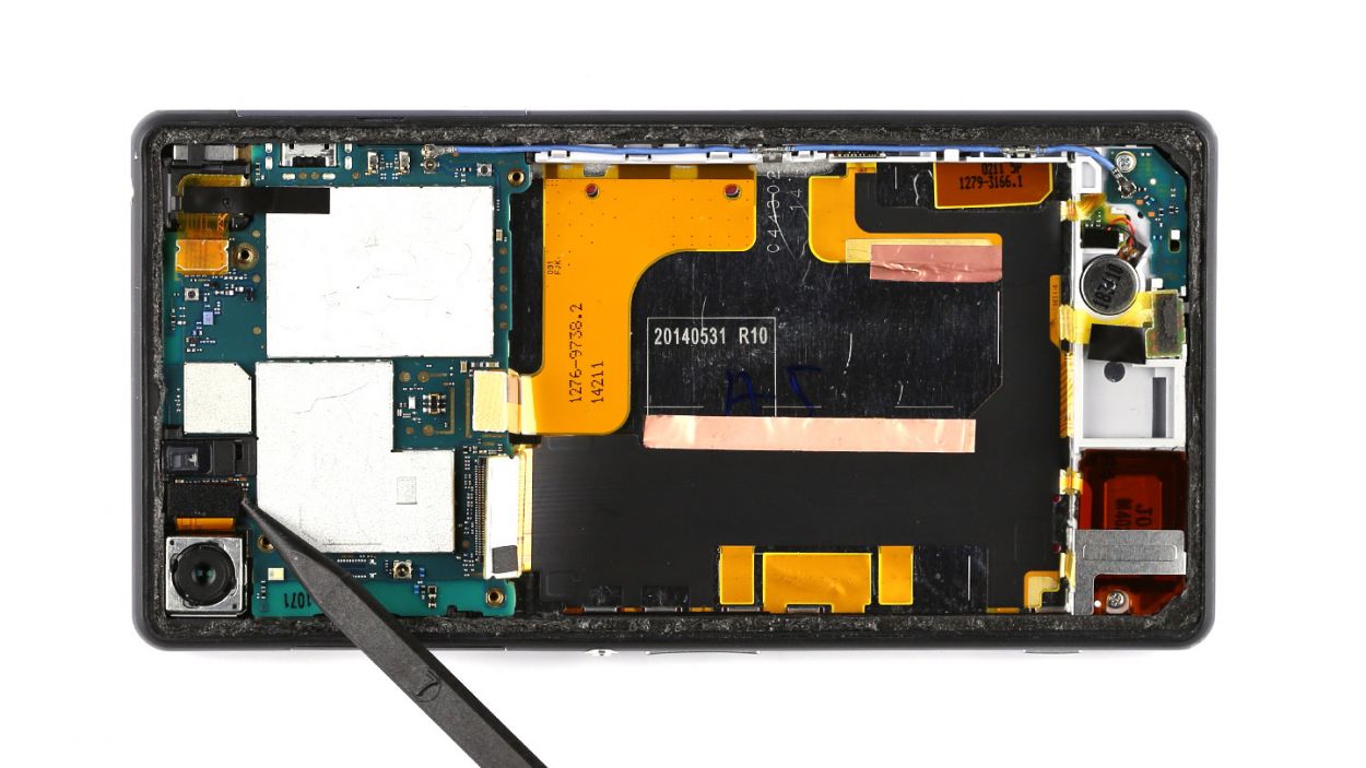
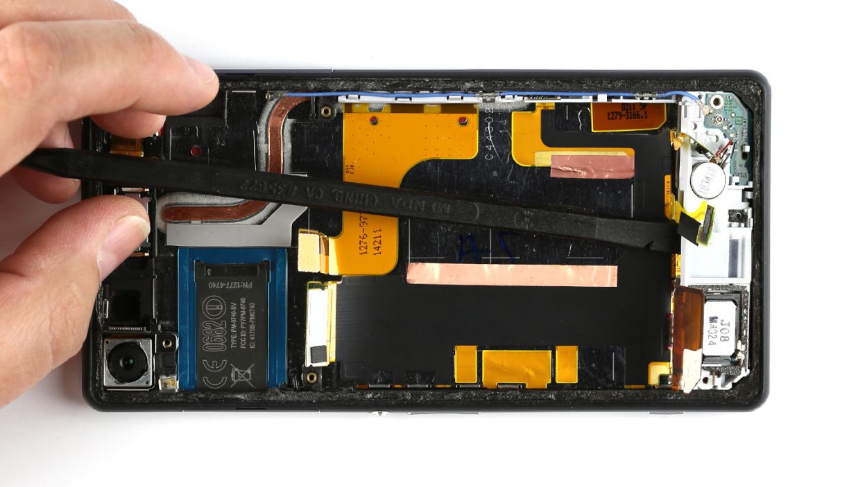
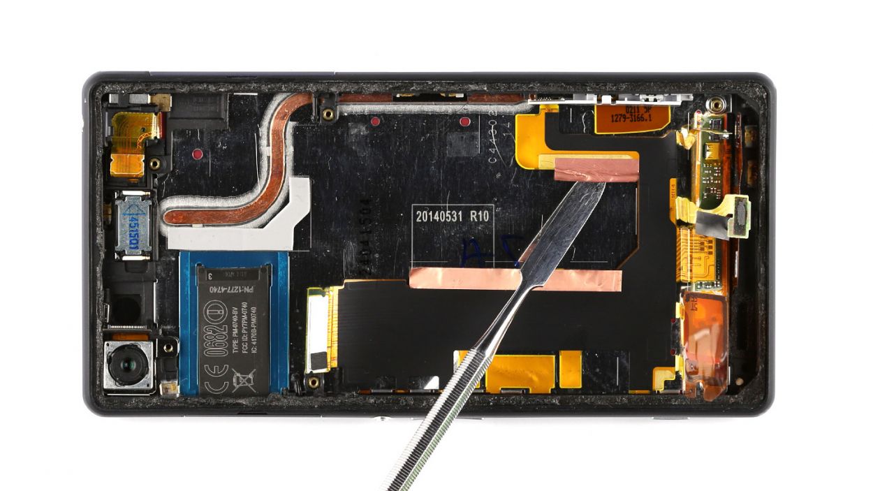
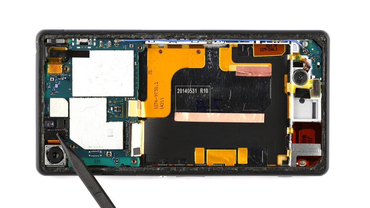
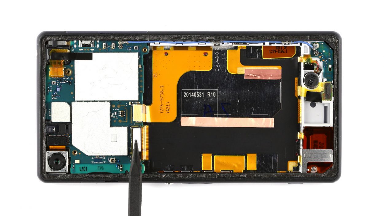
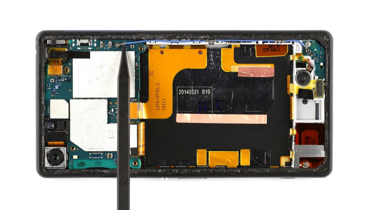
– Gently lift the logic board using the spudger to free it from the enclosure. It’s got a little hook holding on, but no worries! There’s a handy opening at the bottom just waiting for your spudger to slide in.
– Now, with a little finesse, take the logic board out with your fingers. A slight twist to the left will help it slide right out without snagging on those pesky connectors.
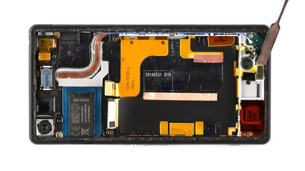
Step 8
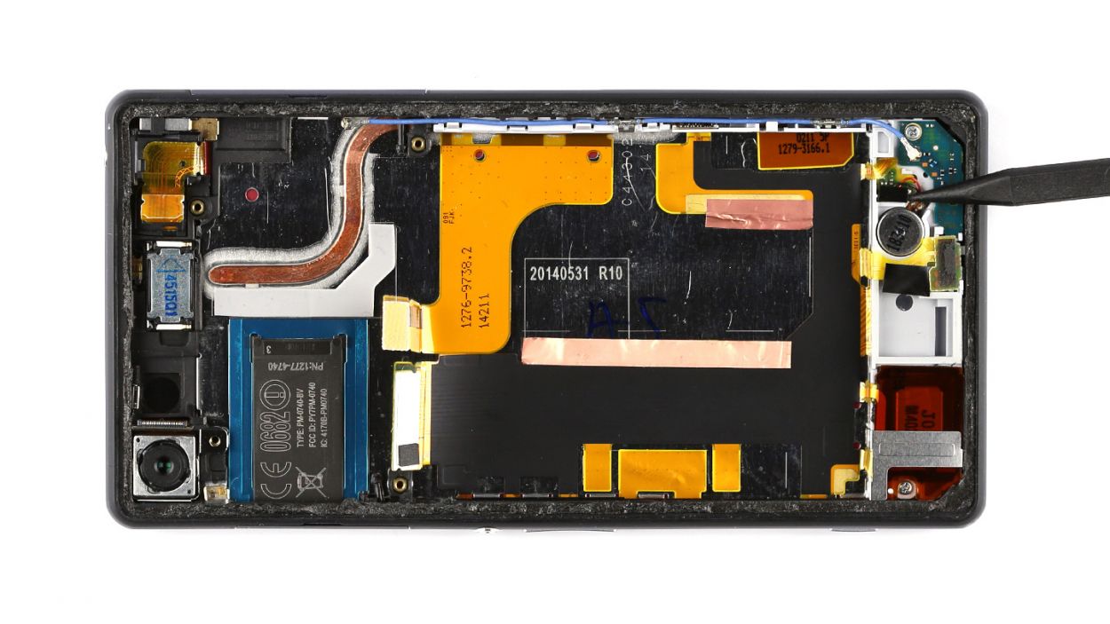
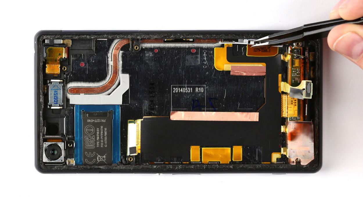
– Gently pop off the antenna cable from the sub-board—easy does it!
– Unplug the vibrator motor’s connection from the sub-board with a little finesse.
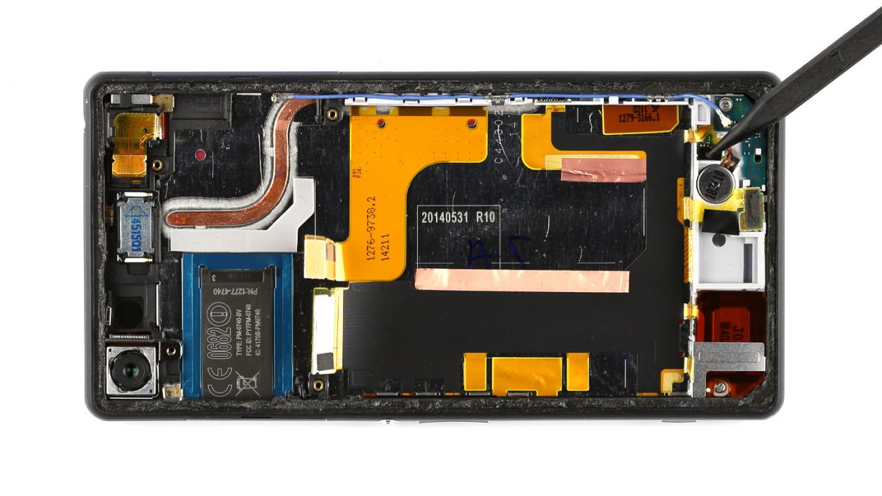
Step 9
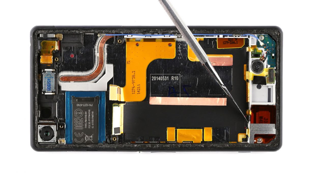
– There’s a metal bracket keeping the speaker and sub-board snug as a bug. It’s hooked onto the enclosure like a trusty sidekick. Grab your steel spatula and gently slide it between a retaining clip and the bracket to give it a little nudge and release it.
– Now, go ahead and lift that metal bracket away from the enclosure. You’re doing great!
Step 10


– Alright, this is the fun part! Gently pry the vibrator motor’s contact away from the sub-board using your trusty steel spatula. Make sure to slide that spatula in between the sub-board and the contact plate, nice and smooth.
– Time to get the microphone out of its cozy little spot on the sub-board! Use your steel spatula to give it a gentle lift. Easy does it!
– Whoa, almost there! Use a little oomph to detach those speaker contacts from the sub-board. They’re stuck to that reddish-brown backing material, but don’t worry, it’s just a matter of giving them a friendly tug.
– It’s time to unscrew the sub-board! You’ll need to remove those two 3.4 mm Phillips screws to get the process started. Take your time, and don’t strip those screws!
– Get your spudger ready for some gentle prying magic! Carefully insert it in the middle of the sub-board, making sure not to damage those pesky flexible flat cables. You got this!
– The final stretch! Gently pry the sub-board out of its enclosure, and voilà! You’ve accomplished the first step in your repair journey. If you need help, you can always schedule a repair
Step 11
– Gently detach the antenna cable that’s snugly secured to the side of your smartphone’s enclosure. Grab a pair of tweezers and carefully pull it away, making sure not to squish it in the process. You’ve got this!
Step 12
– Grab your trusty steel spatula and gently pry away the flexible flat cable from the charger contact. Just slide that spatula between the cable and the enclosure. Remember, that cable is glued down, so a little heat can work wonders! If the glue is being stubborn, warm up the enclosure with some hot air.
– Now, go ahead and remove that flexible flat cable from your smartphone.
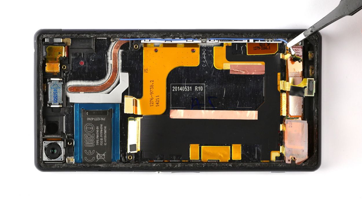
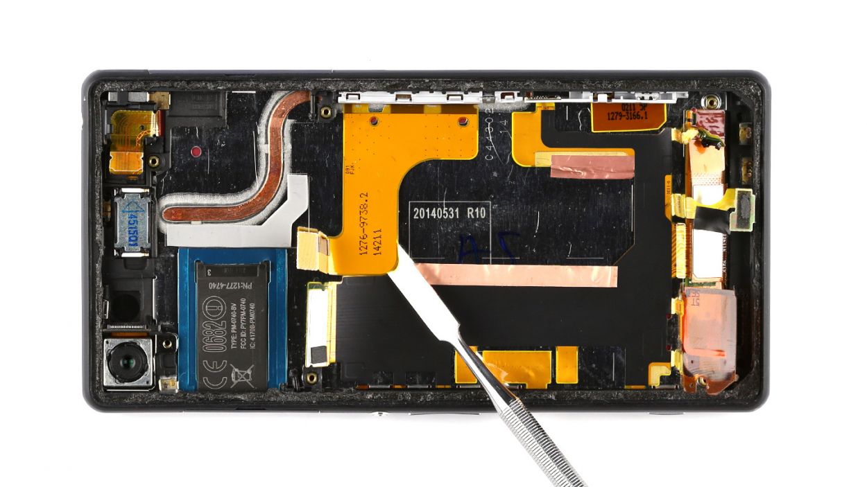
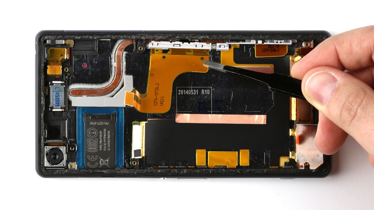
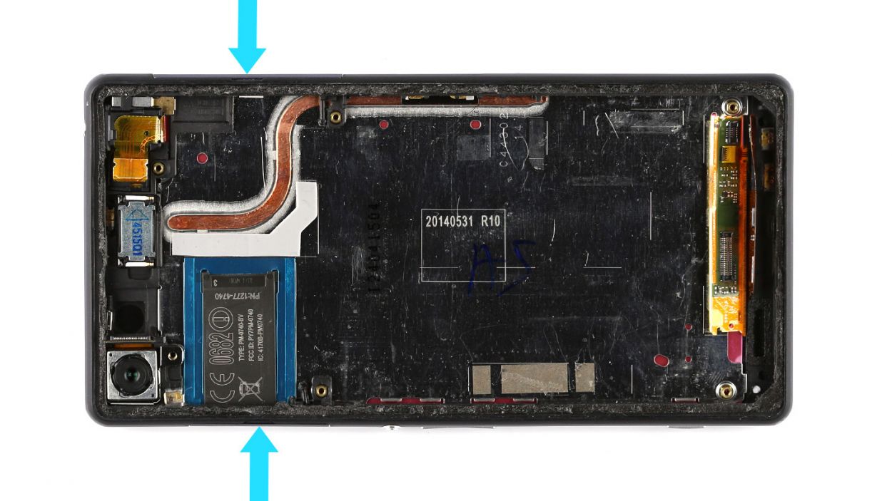
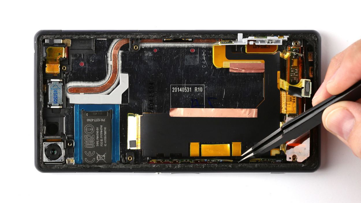
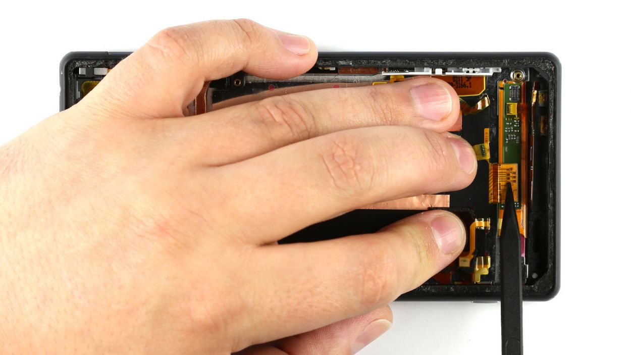
Step 13


– Gently fold the flexible flat cable to reveal the hidden contact of the main flexible flat cable beneath it. Use one hand to hold the contacts for the vibrator motor, speaker, and voice microphone steady.
– With your trusty spudger, carefully pry the main flexible flat cable away from the display.
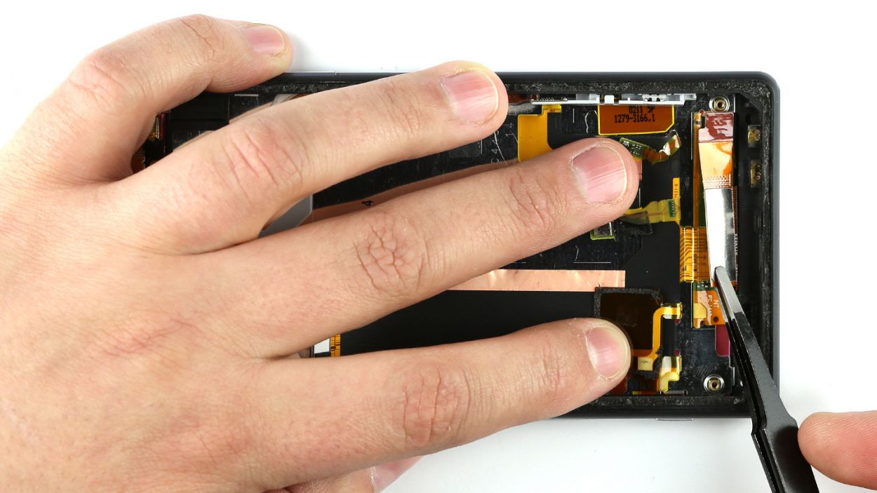
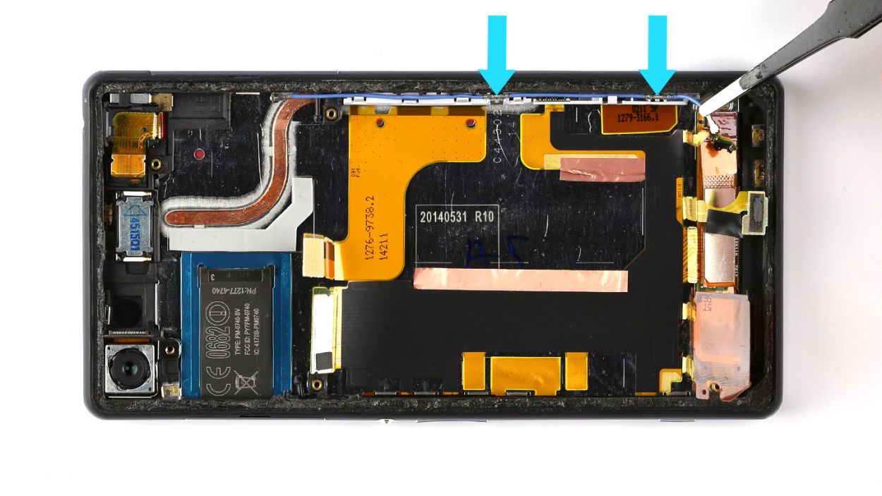
– The flexible flat cable is stuck to the enclosure. Use your steel spatula to gently wedge between the enclosure and the flexible flat cable. If that glue is being a little too clingy, feel free to warm up the enclosure with some hot air.
– The flexible flat cable is secured to the enclosure on both sides. Apply a bit of force and use tweezers to pull the flexible flat cable free. Just a heads up: there are tiny parts on the flexible flat cable that could easily break off, so take it slow and steady.
Step 14

– Not all replacement parts have the same features, so you may have to transfer the following parts:3.5 mm jack socketSpeaker for earpieceRear cameraType plateCover for SIM card slotCover for microSD slot
– 3.5 mm jack socket
– Speaker for earpiece
– Rear camera
– Type plate
– Cover for SIM card slot
– Cover for microSD slot
Step 15


– Gently place the main flexible flat cable back where it belongs, like tucking in a cozy blanket.
– Grab your trusty tweezers and click that flexible flat cable into position on both sides. Just a friendly reminder: watch out for those tiny parts that might want to escape from the cable!
– Now, press the flexible flat cable firmly onto the enclosure so the adhesive surfaces can bond like best friends. Give a little extra love to the contacts for the microphone, vibrator motor, and speaker with your hand, making it easier to connect the display.
– Finally, fold the flexible flat cable back over to keep the display contact cozy and covered. You’re doing great!
Step 16

– Carefully tuck the charger’s flexible flat cable back into its cozy little home in the enclosure. Make sure it’s snugly in the right spot, and give it a gentle press with your fingers to ensure the glue sticks like a champ!
Step 17
– Attach the antenna cable to your smartphone again. There are two metallic sleeves on the cable. You have to press these sleeves into the two metallic brackets. This way, the cable will be in the right position in the enclosure.
Step 18


– Gently place the sub-board back where it belongs, just like tucking in a cozy blanket.
– Secure the sub-board to the enclosure with those trusty two screws—2 x 3.4 mm Phillips screws, to be exact. Tighten them up snugly!
– Nestle the microphone and the vibrator motor contact into their special spots, then fold the speaker contact back over to reconnect it to the speaker. You’re almost there!
Step 19

– Secure the bracket back over the speaker in the enclosure. You should hear a gentle click when it’s snugly in place.
Step 20
– Time to plug in that vibrator motor to the sub-board and get things buzzing!
– Now, let’s get that antenna cable reconnected so you can stay in touch with the world!
Step 21

– Gently place the logic board back into its cozy spot in the enclosure. Ensure that the Micro-USB port slides right into its designated opening. You should hear a satisfying little click as the logic board settles into place. A gentle twist, similar to how you removed it, can help prevent it from snagging on any connectors. Just keep an eye out to make sure those connectors don’t get trapped underneath the logic board.
Step 22

– Snap the rear camera onto the logic board – you’ll hear a satisfying click when it’s in place!
– Connect the controls to the logic board. Piece of cake!
– Plug in the charging port. Easy peasy!
– Reattach the logic board to the sub-board with the antenna cable. Almost there!
– Pop the 3.5 mm jack socket back onto the logic board. You’re a rockstar!
Step 23

– Carefully place the black antenna back in its original spot.
– Secure the logic board and the antenna to the enclosure using the two 2 x 3.4 mm Phillips screws.


Step 25
– Alright, it’s time to wrap things up by putting that back cover on again!
– Don’t worry, the old glue is still hanging in there, ready to do its job.
– Just place the back cover on, give it a little heat, and then press it down gently for a bit. You’ve got this!
Step 26


– Slide that cover to pop open the SIM card slot like a pro!
– Carefully place the SIM card back in, making sure it’s lined up just right on the tray. If it’s snug and happy in its spot, you can slide both parts back into the SIM card slot together.
– Now, let’s open up the microSD card slot and give it some love.
– Gently insert the microSD card back in, ensuring it’s perfectly aligned.
– Finally, close both covers up again, and you’re all set!